Advertisement
Quick Links
Advertisement

Summary of Contents for Azco RM900
- Page 1 O W N E R ’ S M A N U A L AZCO INDUSTRIES LIMITED...
- Page 2 4. Ensure that the rear exhaust vents are not in contact with or near to fl am- gently adhered to. mable materials. 5. All Azco products are designed to operate under vacuum. DO NOT operate Any modifi cation to the Ozone Generator, and/or related equipment, shall under pressure.
- Page 3 All responsibility for any damage or injury resulting from neglecting materials. these precautions, or by non-observance of ordinary caution and due care required in handling, operating, maintenance or repair, even if not expressly mentioned in this book, will be disclaimed by Azco Indus- tries Limited.
-
Page 4: Table Of Contents
Table of Contents ORIENTATION INSTALLATION START-UP START-UP CONT. START-UP CONT. OUTPUT CHART TROUBLESHOOTING... -
Page 6: Orientation
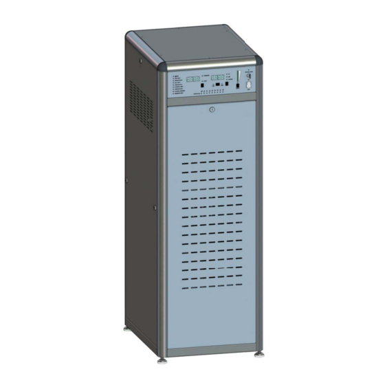
ORIENTATION Front 1. System Status LED’s 6. ORP/Vacuum Switch 2. Pressure/Flow Display PCB Status LED 3. Pressure/Flow Toggle Switch 8. 10-position switch and indicator 4. ORP/Vacuum Display 9. Control keylock 5. ORP Low/High Toggle 10. On/Off switch. (Main shut off circuit breaker on rear panel) *There are a total of 8 separate blocks internally. - Page 7 Rear 1. Main Circuit Breaker 8. Female AMP-37 pin PLC connector (Male adapter included) 2. Power plug receptacle (power plug included) 3. 1/2” NPT Female brass connector (For Oxygen in) 4. 5/8” O.D. S.S. Compression fi tting (For Ozone out) 5.
-
Page 8: Installation
2. Environmental • Amb. Temp. <35 degree Celsius AZCO Industries LTD. is not liable for water release due to a failure of any part or failure to control the external water • Amb. R.H. < 85% supply, The customer shall provide proper drainage of the space below the unit. Going beyond the pressure limits •... - Page 9 fl ow in the correct direction for the safety of the equipment as well as the potential output of the machine. Electrical Diagram 4: RM900’s Back Lower side shows the Coolant Outlet #1 and inlet #2 for the cooling water connections...
-
Page 10: Start-Up
Step 3: Step 1: Adjust ORP Levels Turn on the main power to the RM900 by lifting the Cir- • Hold “high” and press + or - cuit breaker (#1) on the back panel of the RM900. •... - Page 11 Step 3: Step 3: Before any adjustments are made make sure that the control lock (#1 on front panel) is disabled. If the ORP is not going to be used then you must install the ORP jumper(note:). Using the Jumper will zero display #4 and override the ORP settings.
-
Page 12: Start-Up Cont
(Note: • 12 degrees Celsius optimal no restriction between the outlet of the RM900 and the The pressure gauge will not function at this time) inlet of the Water chiller. The system should be as free 4. - Page 13 Step 7: Clearing Status LED’s Step 5: Check the status lights on the Left of the control panel. At this point one of the vacuum LED’s is the only one that should be red, as the vacuum still has to be adjusted. If any LED other than vacuum is red something is wrong.
-
Page 14: Start-Up Cont
START-UP CONT. Step 8: Step 8: Balancing the vacuum and pressure to achieve the 1. Switch Main display to vacuum fl ow required can be quite tricky, but with patience and the 2. Turn on pump(s) to create suction following steps the process should be easy. 3. -
Page 15: Output Chart
Output Chart... -
Page 16: Troubleshooting
Troubleshooting...
Need help?
Do you have a question about the RM900 and is the answer not in the manual?
Questions and answers