Table of Contents
Advertisement
Quick Links
Advertisement
Chapters
Table of Contents

Related Manuals for Acer Aspire 4250


Summary of Contents for Acer Aspire 4250
- Page 1 Aspire 4250 SERVICEGUIDE...
-
Page 2: Revision History
Copyright Copyright © 2011 by Acer Incorporated. All rights reserved. No part of this publication may be reproduced, transmitted, transcribed, stored in a retrieval system, or translated into any language or computer language, in any form or by any means, electronic, mechanical, magnetic, optical, chemical, manual or otherwise, without the prior written permission of Acer Incorporated. - Page 3 Conventions The following conventions are used in this manual: WARNING: Indicates a potential for personal injury. CAUTION: Indicates a potential loss of data or damage to equipment. IMPORTANT: Indicates information that is important to know for the proper completion of a procedure, choice of an option, or completing a task. The following typographical conventions are used in this document: Book titles, directory names, file names, path names, and program/process names are shown in italics.
-
Page 4: General Information
Acer-authorized Service Providers: The Acer office may have a different part number code than those given in the FRU list in this service guide. A list must be provided by the regional Acer office to order FRU parts for repair and service of customer machines. - Page 5 CHAPTER 1 Hardware Specifications Features........1-5 Operating System .
- Page 6 LCD Inverter (not available with this model) ... . 1-34 Display Supported Resolution (LCD Supported Resolution) 1-35 Display Supported Resolution (GPU Supported Resolution) 1-35 Bluetooth Interface (not available with this model) ..1-36 Mini Card .
- Page 7 Crisis Disk Recovery ....... . 2-28 CHAPTER 3 Machine Maintenance Procedures Introduction .
- Page 8 Camera Module Removal......3-38 Camera Module Installation ......3-39 LCD Panel Removal.
-
Page 9: Table Of Contents
Model Definition and Configuration Acer Aspire 4250....... . . 7-1... - Page 11 CHAPTER Hardware Specifications...
- Page 12 Features........1-5 Operating System .
- Page 13 Audio Interface ..........1-38 Battery .
-
Page 15: Hardware Specifications And Configurations
Single-channel DDR3 SDRAM, supports 2 DIMMS: Up to 4 GB of DDR3 system memory, upgradable to 8 GB using two soDIMM modules Display 14" HD 1366 x 768 pixel resolution, high-brightness (220-nit) Acer CineCrystal™ LED-backlit TFT LCD Mercury-free, environment-friendly 16:9 aspect ratio... -
Page 16: Graphics
Graphics Aspire 4250 ATI Radeon™ HD 6310 Graphics with 256 MB of dedicated system memory, supporting Unified Video Decoder 3 (UVD3), OpenCL™ 1.1, OpenGL OpenEXR High Dynamic-Range (HDR) technology, Shader Model 5.0, Microsoft ® DirectX ATI Radeon™ HD 6250 Graphics with 256 MB of dedicated system memory, supporting Unified Video Decoder 3 (UVD3), OpenCL™... -
Page 17: Optical Media Drive
Write: 24X CD-R, 16X CD-RW, 8X DVD-R, 8X DVD+R, 4X DVD-R DL, 4X DVD+R DL, 6X DVD-RW, 8X DVD+RW, 5X DVD-RAM Communication Acer Video Conference: Acer Crystal Eye webcam, 1280 x 1024 resolution WLAN: Acer InviLink™ Nplify™ 802.11b/g/n Wi-Fi CERTIFIED™ Acer InviLink™ 802.11b/g Wi-Fi CERTIFIED™... -
Page 18: Special Keys And Controls
Special Keys and Controls Keyboard 105-US/106-UK key New Acer TM7T flat keyboard with international language support Touchpad Multi-gesture touchpad, supporting two-finger scroll, pinch, rotate, flip Media keys Media control keys (printed on keyboard): play/pause, stop, previous, next, volume up, volume down I/O Ports 2-in-1 card reader (SD™, MMC) -
Page 19: Software
Acer Crystal Eye ® Microsoft Silverlight™ Skype™ Windows Live™ Essentials Web links and utilities Acer Accessory Store (Belgium, France, Germany, Italy, Netherlands, Spain, Sweden, UK only) Acer Identity Card Acer Registration Acer Updater ® eBay shortcut 2009 (Canada, France, Germany, Italy, Mexico, Spain, UK, US only) -
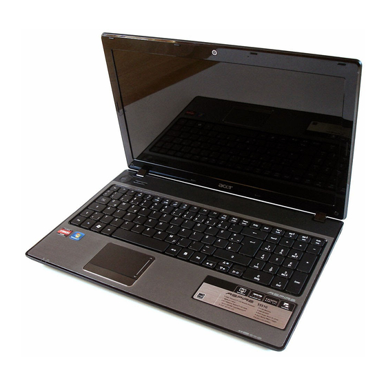
Page 20: Opened Front View
Notebook Tour Figure 1-1. Opened Front View Table 1-1. Opened Front View Icon Acer Crystal Eye webcam Display screen Power button Keyboard Touchpad Click buttons (left, and right) Microphone 1-10 Item Web camera for video communication. (only for certain models) - Page 21 Table 1-1. Opened Front View Icon Power indicator Battery indicator HDD indicator Communication indicator Palmrest Speaker Hardware Specifications and Configurations Item Indicates the computer's power status. Indicates the computer's battery status. 1. Charging: The light shows amber when the battery is charging. 2.
- Page 22 Figure 1-2. Closed Front View Table 1-2. Closed Front View Icon Microphone jack Headphone/speaker/li ne-out jack 2-in-1 Card Reader 1-12 Item Accepts inputs from external microphones. Connects to audio line-out devices (e.g., speakers, headphones). Accepts Secure Digital (SD), MultiMediaCard (MMC). Note: Push to remove/install the card.
- Page 23 Figure 1-3. Top View Table 1-3. Top View Icon Item Description Acer Logo Acer Aspire 4250 Logo 1-13 Hardware Specifications and Configurations...
- Page 24 Figure 1-4. Rear View Table 1-4. Rear View Icon Item Description Battery bay Houses the computer's battery pack. 1-14 Hardware Specifications and Configurations...
- Page 25 Figure 1-5. Left View Table 1-5. Left View Icon Kensington lock slot DC-in jack Ventilation slots External display (VGA) port Ethernet (RJ-45) port USB 2.0 port Hardware Specifications and Configurations Item Connects to a Kensington-compatible computer security lock. Note: Wrap the computer security lock cable around an immovable object such as a table or handle of a locked drawer.
- Page 26 Figure 1-6. Right View Table 1-6. Right View Icon USB 2.0 ports Optical drive Optical disk access indicator Optical drive eject button Optical drive eject hole 1-16 Item Connect to USB 2.0 devices (e.g., USB mouse, USB camera). Internal optical drive; accepts CDs or DVDs.
- Page 27 Figure 1-7. Base View Table 1-7. Base View Icon Battery bay Battery lock Ventilation slots Battery release latch Hardware Specifications and Configurations Item Houses the computer's battery pack. Locks the battery in position. Enable the computer to stay cool, even after prolonged use.
-
Page 28: Touchpad Basics
Touchpad Basics Figure 1-8. Touchpad Move your finger across the Touchpad (1) to move the cursor. Press the left (2) and right (3) buttons located beneath the Touchpad to perform selection and execution functions. These two buttons are the equivalent of the left and right buttons on a mouse. -
Page 29: Using The Keyboard
Using the Keyboard The computer has a close-to-full-sized keyboard and an embedded numeric keypad, separate cursor, lock, function and special keys. Figure 1-9. Keyboard Lock Keys Lock Keys The keyboard has three lock keys which can be toggled on and off. Lock key Caps Lock When Caps Lock is on, all alphabetic characters typed are in uppercase. -
Page 30: Windows Keys
Windows Keys The keyboard has two keys that perform Windows-specific functions. Windows Logo key Application key Windows Logo Pressed alone, this key has the same effect as clicking on the Windows Start button; it launches the Start menu. It can also be used with other keys to provide a variety of functions. -
Page 31: Hotkeys
Hotkeys The computer employs hotkeys or key combinations to access most of the computer's controls like screen brightness and volume output. Figure 1-10. Keyboard Hotkeys To activate hotkeys, press and hold the <Fn> key before pressing the other key in the hockey combination. - Page 32 Hot key Icon <Fn> + < > <Fn> + <Home> <Fn> + <Pg Up> <Fn> + <Pg Dn> <Fn> + <End> 1-22 Function Volume down Decreases the sound volume. Play/Pause Plays or pauses media files Stop Stops media file Previous Plays the previous media file Next Plays the next media file...
- Page 33 System Block Diagram Figure 1-11. System Block Diagram 1-23 Hardware Specifications and Configurations...
-
Page 34: Specification Tables
Specification Tables Computer specifications Item Dimensions Length Width Height (front to rear) Weight (equipped with optical drive, flash drive, and battery) Input power Operating voltage Operating current Temperature Operating (not writing to optical disc) Operating (writing to optical disc) Nonoperating Relative humidity Operating Nonoperating... -
Page 35: Processor
System Board Major Chips Item Core logic AMD Brazos platform Hudson-M1 AMD Radeon™ HD 6310 Graphics AMD Radeon™ HD 6250 Graphics Atheros 8151 USB 2.0 AMD A50M Fusion™ Controller Hub Super I/O controller AMD A50M Fusion™ Controller Hub Wireless Atheros HB93/HB95/ HB97, Broadcom 943225/43225/ 4313/ 4312, RTL8192 PCMCIA Audio codec... -
Page 36: Cpu Fan True Value Table
CPU Fan True Value Table Temperature (°C) Fan on = 45C; Fan Off = 42C Fan on = 50C; Fan Off = 48C Fan on = 58C; Fan Off = 56C Fan on = 63C; Fan Off = 61C Fan on = 82C; Fan Off = 80C Fan on = 92C;... -
Page 37: Memory Combinations
Memory Combinations Slot 1 (MB) 1024 1024 2048 2048 4096 4096 Video Interface Item Chipset Package Interface Compatibility Sampling rate BIOS Item BIOS vendor BIOS Version BIOS ROM type BIOS ROM size Features Hardware Specifications and Configurations Slot 2 (MB) 1024 1024 2048... -
Page 38: Lan Interface
Specification Atheros 8151 RJ45 RJ45 at the left side Supports 10/100/1000 Specification Acer AC4T_A10B keyboard 86-US/87-UK/91-JP key Plug USB keyboard to the USB port directly: Yes Phantom key auto detect Overlay numeric keypad Support independent pgdn/pgup/pgup/home/end keys Support reverse T cursor keys... -
Page 39: Hard Disk Drive (Avl Components)
Hard Disk Drive (AVL components) Item Vendor & Hitachi Model Name HTS545025B9A300 Seagate ST9250315AS WD2500BEVT, WD2500BPVT TOSHIBA MK2559GSXP Capacity (GB) Bytes per sector Data heads Drive Format Disks Spindle speed (RPM) Performance Specifications Buffer size Interface Fast data transfer rate (Gbits / sec, max) Media data 875, 300, 97, 97,... -
Page 40: Hard Disk Drive (Avl Components) (Continued)
Hard Disk Drive (AVL components) (Continued) Item Vendor & Hitachi Model Name HTS547564A9E384 Seagate ST9640320AS WD6400BEVT, WD6400BPVT TOSHIBA MK6459GSXP Capacity (GB) Bytes per sector Data heads Drive Format Disks Spindle speed (RPM) Performance Specifications Buffer size Interface Fast data transfer rate (Gbits / sec, max) Media data... -
Page 41: Super-Multi Drive
Super-Multi Drive Item Vendor & HLDS Model name GT32N Performance With CD Specification Diskette Transfer rate Sustained: (KB/sec) Max 3.6 (24x) Buffer Memory Interface Applicable disc DVD: format DVD-ROM: 4.7GB (Single Layer) 8.5GB (Dual Layer) DVD-R: 3.95GB (Ver. 1.0: read only) 4.7GB (Ver. 2.0 for Authoring: read only) 4.7GB (Ver. -
Page 42: Super-Multi Drive (Continued)
Super-Multi Drive (Continued) Item Vendor & Pioneer DVR-TD10RS Model name Performance With CD Specification Diskette Transfer rate Sustained: (KB/sec) - CD-ROM inside - CD-ROM outside 3.6 Buffer Memory Interface Applicable disc KODAK PhotoCD Single and format Multi-session CD Extra (CDPLUS) Video CD CD text data (Read/Write) CD-R discs (Read/Write) -
Page 43: Super-Multi Drive (Continued)
Super-Multi Drive (Continued) Item Vendor & Sony AD-7585H Model name Performance With CD Specification Diskette Transfer rate Sustained: (KB/sec) - CD-ROM inside 1,571 - CD-ROM outside 3,650 Buffer Memory Interface Applicable disc DVD: format DVD-ROM (DVD-5, DVD-9, DVD-10, DVD-18), DVD-Video, DVD-Audio, SACD (Hybrid), UDF DVD, DVD-R, DVD-R DL, DVD-R 3.95 GB, DVD-R Authoring, DVD-R Multi-Border,... -
Page 44: Led 14.0
LED 14.0” Item Vendor & Model name Screen Diagonal (mm) Active Area (mm) Display resolution (pixels) Pixel Pitch (mm) Typical White Luminance (cd/m also called Brightness Contrast Ratio Response Time (Optical Rise Time/Fall Time) msec Typical Power Consumption (watt) Weight (without inverter) Physical Size (mm) Electrical Interface Viewing Angle (degree) -
Page 45: Display Supported Resolution (Lcd Supported Resolution)
Display Supported Resolution (LCD Supported Resolution) Resolution 800x600p/60Hz 16:9 1024x768p/60Hz 16:9 1280x600/60Hz 16:9 1280x720/60Hz 16:9 1280x768/60Hz 16:9 1360x768/60Hz 16:9 1366x768/60Hz 16:9 Graphics Controller Item VGA Chip Supports Display Supported Resolution (GPU Supported Resolution) Resolution 640x480p/60Hz 16:9 800x600p/60Hz 16:9 1024x768p/60Hz 16:9 1280x600/60Hz 16:9 1280x720/60Hz 16:9 1280x768/60Hz 16:9... -
Page 46: Bluetooth Interface (Not Available With This Model)
Bluetooth Interface (not available with this model) Item Chipset Data throughput Protocol Interface Connector type Supported protocol Bluetooth Module (not available with this model) Item Controller Feature Controller Camera Item Vendor & Model Suyin 1.3MB HF1316, HF1315 Type CMOS image sensor S5K6A1GX03 Mini Card Item Number supported... -
Page 47: Audio Codec And Amplifier
Audio Codec and Amplifier Item Audio Conexant 20584 Controller Features Meets Microsoft WLP (Windows Logo Program) audio requirements High performance DACs with digital >110dB and analog 98dB (A -weighting) signal-to-noise High performance ADCs with digital > 100dB and analog 90dB (A -Weighting) signal-to-noise ratio Six DAC channels support 16/20/24 -bit PCM format for 5.1 sound playback... -
Page 48: Audio Interface
Item Amplifier CX20584 embedded amplifier Audio Interface Item Audio Controller Audio onboard or optional Mono or Stereo Resolution Compatibility Sampling rate Internal microphone Internal speaker/quantity Wireless Module 802.11b/g/n Item Chipset Atheros HB93/HB95/HB97 Data 11-54 Mbps, up to 270 Mbps for throughput Draft-N Protocol... -
Page 49: Vram (Not Available In This Model)
VRAM (not available in this model) Item Chipset Memory size Interface USB Port Item USB compliance level EHCI Number of USB port(s) Location Output Current HDMI Port Item Compliance level Data throughput Number of HDMI port(s) Location AC Adapter Item Input rating Maximum input AC current Inrush current... -
Page 50: System Power Management
System Power Management Item Mech. Off (G3) Soft Off (G2/S5) Working (G0/S0) Suspend to RAM (S3) Save to Disk (S4) Card Reader Item Chipset Package Maximum supported size Features 1-40 Specification Al devices in the system are turned off completely. OS initiated shutdown. -
Page 51: System Led Indicator
System LED Indicator Item Lock System state HDD access state Wireless state Power button backlight Battery state Back up state Arcade module state Finger print module state System DMA Specification Legacy Mode DMA0 DMA1 DMA2 DMA3 DMA4 DMA5 DMA6 DMA7 *ExpressCard controller can use DMA 1, 2, or 5. - Page 52 System Interrupt Specification Hardware IRQ IRQ0 IRQ1 IRQ8 IRQ12 IRQ13 IRQ16 IRQ17 IRQ18 IRQ19 IRQ81 IRQ82 IRQ83 IRQ84 IRQ85 IRQ86 IRQ87 IRQ88 IRQ89 IRQ90 IRQ91 IRQ92 IRQ93 IRQ94 IRQ95 IRQ96 1-42 System Function High precision event timer Standard PS/2 Keyboard High precision event timer Synaptics PS/2 Port Touchpad Numeric data processor...
- Page 53 Hardware IRQ IRQ97 IRQ98 IRQ99 IRQ100 IRQ101 IRQ102 IRQ103 IRQ104 IRQ105 IRQ106 IRQ107 IRQ108 IRQ109 IRQ172 IRQ173 IRQ174 IRQ175 IRQ176 IRQ177 IRQ178 IRQ179 IRQ180 IRQ181 IRQ182 IRQ183 IRQ184 IRQ185 IRQ186 IRQ187 IRQ188 IRQ189 IRQ190 IRQ-2 Hardware Specifications and Configurations System Function Microsoft ACPI-Compliant System Microsoft ACPI-Compliant System Microsoft ACPI-Compliant System...
- Page 54 System IO Address Map I/O address (hex) 000 - CF7 000 - 00F 000 - 01F 020 - 021 02E - 02F 040 - 043 070 - 071 072 - 073 081 - 08F 0A0 - 0A1 0B0 - 0B1 0C0 - 0DF 0F0 - 0FE 3B0 - 3BB...
- Page 55 I/O address (hex) 0D00 - FFFF 2000 - 2FFF 3000 - 30FF 3100 - 310F 3110 - 3117 3118 - 311F 3120 - 3123 3124 - 3127 Hardware Specifications and Configurations System Function (shipping configuration) PCI bus PCI standard PCI-to-PCI bridge AMD Radeon HD 6250 Graphics Standard AHCI1.0 Serial ATA Controller Standard AHCI1.0 Serial ATA Controller...
- Page 56 1-46 Hardware Specifications and Configurations...
- Page 57 CHAPTER System Utilities...
- Page 58 BIOS Setup Utility ....... . 2-3 Navigating the BIOS Utility ......2-3 BIOS .
-
Page 59: System Utilities
System Utilities BIOS Setup Utility This utility is a hardware configuration program built into a computer’s BIOS (Basic Input/Output System). The utility is pre-configured and optimized so most users do not need to run it. If configuration problems occur, the setup utility may need to be run. Refer to Chapter 4, Troubleshooting when a problem arises. -
Page 60: Bios
1066 MHz Hitachi HTS545016B9A300 100513PBPB04ECCYXROL TSSTcorp CDDVDW TS-L633F V1.04 ATI VERO12.036.000.003.039043 123456789 Acer 20D4DD9869FEDF11802C60EB698FC1A8 Figure Description CPU (central processing unit) type and speed of system Speed of the CPU Model name of HDD (hard disk drive) installed on primary IDE... - Page 61 Table 2-1. BIOS Information (Continued) Parameter System BIOS Version VGA BIOS Version Serial Number Asset Tag Number Product Name Manufacturer Name UUID System Utilities Description System BIOS version VGA (video graphics array) firmware version of system Serial number of unit Asset tag number of system Product name of the system Manufacturer of system...
-
Page 62: Main
Main The Main tab allows the user to set system time and date, enable or disable boot option and enable or disable recovery. System Time System Date Total Memory Video Memory Graphic Mode Quiet Boot Network Boot F12 Boot Menu D2D Recovery SATA Mode Figure 2-2. - Page 63 Table 2-2. BIOS Main (Continued) Parameter F12 Boot Menu Option to use boot menu during POST D2D Recovery Option to use D2D Recovery function SATA Mode Option to set SATA controller mode System Utilities Description Format/Option Option: Enabled or Disabled Option: Enabled or Disabled Option: AHCI or IDE...
-
Page 64: Security
Security The Security tab shows parameters that safeguard and protect the computer from unauthorized use. Supervisor Password Is: User Password Is: HDD Password Is: Set Supervisor Password Set User Password Set HDD Password Power on Password Figure 2-3. BIOS Security Table 2-3 describes the parameters shown in Table 2-3. -
Page 65: Setting A Password
Table 2-3. BIOS Security (Continued) Parameter Password on Boot NOTE: NOTE: When prompted to enter password, three attempts are allowed before system halts. Resetting BIOS password may require computer be returned to dealer. Setting a Password Perform the following to set user or supervisor passwords: 1. -
Page 66: Removing A Password
Removing a Password Perform the following: 1. Use the ↑ and ↓ keys to highlight Set Supervisor Password and press Enter. The Set Supervisor Password dialog box appears: Figure 2-5. Set Supervisor Password 2. Type current password in Enter Current Password field and press Enter. 3. - Page 67 Figure 2-7. Setup Notice The password setting is complete after the user presses Enter. If the password entered does not match the current password, the screen shows the Setup Warning dialog. Figure 2-8. Setup Warning: Invalid Password If new password and confirm new password strings do not match, the Setup Warning dialog appears (Figure Figure 2-9.
-
Page 68: Boot
Boot The Boot tab allows changes to the order of boot devices used to load the operating system. Bootable devices include the: USB diskette drives Onboard hard disk drive DVD drive in the module bay Use ↑ and ↓ keys to select a device and press F5 or F6 to change the value. Boot priority order: 1. -
Page 69: Exit
Exit The Exit tab allows users to save or discard changes and quit the BIOS Setup Utility. Exit Saving Changes Exit Discarding Changes Load Setup Defaults Discard Changes Save Changes Figure 2-11. BIOS Exit Table 2-4 describes the parameters in Table 2-4. -
Page 70: Bios Flash Utilities
BIOS Flash Utilities BIOS Flash memory updates are required for the following conditions: New versions of system programs New features or options Restore a BIOS when it becomes corrupted. Use the Flash utility to update the system BIOS Flash ROM. NOTE: NOTE: If a Crisis Recovery Disc is not available, create one before Flash utility is used. -
Page 71: Dos Flash Utility
DOS Flash Utility Perform the following to use the DOS Flash Utility: 1. Press F2 during boot to enter Setup Menu. 2. Select Boot Menu to modify boot priority order. Example: If using USB HDD to Update BIOS, move USB HDD to position 1. Boot priority order: 1. - Page 72 Figure 2-13. DOS Flash Process 5. Flash is complete when the message, Flash Programming Complete is shown. System will restart automatically when finished. NOTE: NOTE: If AC power is not connected, the following message is shown in the AC power to continue. Figure 2-14.
-
Page 73: Winflash Utility
WinFlash Utility Perform the following to use the WinFlash Utility: 1. Double-click WinFlash executable ZQH_101W.EXE. 2. Click OK to begin update. A progress screen is shown. (Figure 2-15) Figure 2-15. InsydeFlash 2-17 System Utilities... -
Page 74: Clearing Bios Passwords
Clearing BIOS Passwords CAUTION: If Power-on Password authentication is enabled, the BIOS password can only be cleared by initiating the Crisis Disk Recovery procedure or flashing the BIOS. See Crisis Disk This section provides details about removing HDD/BIOS passwords. Clear the BIOS Password as follows: NOTE: NOTE: If the BIOS password is incorrectly entered three times, an error is generated. -
Page 75: Removing Bios Passwords
Removing BIOS Passwords (Hardware method) To clear User or Supervisor passwords, remove lower cover and use a metal instrument to short the CMOS jumper. Figure 2-18. CMOS Jumper Table 2-5. CMOS Jumper Item (Software method) If wrong Supervisor Password is entered three times, the message System will halt! is displayed on Figure 2-19. - Page 76 If user is unable to obtain correct password then it must be unlocked. There are two methods to do this. Method 1: If BIOS menu item Power on Password is set to Enabled, then Crisis Recovery disc must be used. Method 2: If BIOS menu item Power on Password is set to Disabled.
-
Page 77: Removing Insyde Hdd Password
Removing Insyde HDD Password Clear the BIOS Password as follows: To reset the BIOS password, perform the following: 1. When the user keys in the wrong password three times, the system reports the error code: Figure 2-21. Unlock Password Prompt 2. -
Page 78: Miscellaneous Tools
Miscellaneous Tools Using DMITools The DMI (Desktop Management Interface) Tool copies BIOS information to EEPROM (Electrically Erasable Programmable Read-Only Memory). Used in the DMI pool for hardware management. When the BIOS shows Verifying DMI pool data, it is checking that the table correlates with the hardware before sending information to the operating system (Windows, etc.). - Page 79 Figure 2-25. Asset Tag Menu Item 5. Press 2 to modify the product name, then press 2 again to modify EEPROM spec. version. Figure 2-26. Product Name Menu Item 2-23 System Utilities...
- Page 80 6. Press 3 to modify serial number key. Figure 2-27. Serial Number Menu Item 7. Press 4 to modify the 1394 GUID number key. Figure 2-28. 1394 GUID Number Menu Item 8. Press 0 to exit. 9. At the command prompt, run VEEPROM.exe to write any changes in the data to the 2-24 System Utilities...
- Page 81 EEPROM. NOTE: NOTE: When using any of the write options, restart the system to make the new DMI data effective. 2-25 System Utilities...
-
Page 82: Using Uuidtools
Using UUIDTools The UUID (Universally Unique Identifier) Tool copies BIOS information to EEPROM (Electrically Erasable Programmable Read-Only Memory). Used in the DMI pool data for hardware management. To update the DMI Pool, perform the following: 1. Unzip UUID package tool to USB Flash Disk. 2. -
Page 83: Using The Lan Mac Eeprom Utility
Current MAC ID of ESN EEPROM : 00269E230844 Compare ACER & OEM S/N of ESN EEPROM : PASS 4. Flash is completed when the message, Compare ACER & OEM S/N of ESN EEPROM: PASS, is shown. 5. At the command prompt, run VEEPROM.EXE to write any changes in the data to the EEPROM. -
Page 84: Crisis Disk Recovery
Crisis Disk Recovery 1. Plug in the USB flash disk. 2. Select the Fast Format option and click Start. Then click Next. 3. Click Format and then Exit to complete the operation. 4. Copy the ZQH.fd file to the USB flash disk root directory and rename to BIOS.fd NOTE: NOTE: Do not place any other *.fd files to the USB flash disk root directory. - Page 85 CHAPTER Machine Maintenance Procedures...
- Page 86 Introduction ........3-5 General Information ......3-5 Recommended Equipment .
- Page 87 LVDS Cable Removal ....... .3-43 LVDS Cable Installation ......3-44...
-
Page 89: Machine Maintenance Procedures
Flat screwdriver Philips screwdriver Plastic tweezers Flat plastic pry Table 3-1. Screw List Size M2.0*3.0 M2.5*6.0 M3.0*3.0 (NI) M2.5*3.0 (NI) M2.5*4.0 M2.0*2.0 M2.5*4.0 (NI) M2.0*5.0 Machine Maintenance Procedures Quantity 86.ARE07.002 86.ARE07.001 86.N1407.007 86.R6Z07.001 86.PSR07.001 86.W4107.002 86.R6Z07.001 86.T23V7.010 Acer Part No. -
Page 90: Maintenance Flowchart
Maintenance Flowchart The flowchart in Figure 3-1 installation sequences. It shows information on what components may need to be removed and installed during servicing. SD Dummy Card Module DIMM Module Figure 3-1. Maintenance Flow shows a graphic representation of the module removal and Battery Keyboard Base... -
Page 91: Getting Started
Getting Started Flowchart Figure 3-1 identifies sections for the removal and install sequence. Follow the order of the sequence to avoid damage to any of the hardware components. Do the following prior to starting any maintenance procedures: 1. Remove power (A) from the system and peripherals 2. -
Page 92: Battery Pack Removal
Battery Pack Removal 1. Put computer on flat surface, battery side is up. 2. Push battery lock/unlock latch (A) to unlock position 3. Push and hold battery release latch (B) to release position 4. Lift battery pack (C) from battery bay Figure 3-3. -
Page 93: Dummy Card Removal
Dummy Card Removal 1. Push dummy card (A) in to release it from the spring latch 2. Remove dummy card (A) Figure 3-4. Dummy Card Dummy Card Installation 1. Insert dummy card (A) 2. Push card until spring latch locks. Machine Maintenance Procedures (Figure 3-4). -
Page 94: Keyboard Removal
Keyboard Removal Prerequisite: Battery Pack Removal 1. Press upward on the seven (7) locking latches until the keyboard disengages and separates from the system Figure 3-5. Keyboard Latches 2. Turn the keyboard over so that the keypad (C) is face down on the palm rest (Figure 3-6). -
Page 95: Keyboard Installation
CAUTION: Keyboard FPC (Flexible Printed Circuit) can be damaged if removed while mainboard connector is locked. Keyboard Installation 1. Put the keyboard face down on the palm rest (C). Refer to 2. Connect keyboard FPC (A) to mainboard connector (B). Refer to 3. -
Page 96: Base Assembly Removal
Base Assembly Removal Prerequisite: Battery Pack Removal 1. Remove twenty four (24) screws securing the base assembly in place (Figure 3-7). Figure 3-7. Base Assembly Screw Location 3-12 Machine Maintenance Procedures... -
Page 97: Base Assembly Installation
2. Lift up the base assembly by starting from the bottom edge of the base assembly. Refer to Figure 3-8. 3. Release the tabs on the bottom edge of the base assembly. 4. Grasp the base assembly and remove the base assembly from the device Figure 3-8. -
Page 98: Odd (Optical Disk Drive) Module Removal
ODD (Optical Disk Drive) Module Removal Prerequisite: Base Assembly Removal 1. Remove ODD module from ODD bay Figure 3-9. ODD Module in Lower Cover 2. Remove two (2) screws (C) from ODD module 3. Remove ODD bracket (D) from ODD module. 4. -
Page 99: Odd Module Installation
ODD Module Installation 1. Install ODD bezel (E) on ODD module 2. Install ODD bracket (D) on ODD module. 3. Secure two (2) screws (C) to secure the bracket (D) to the back of ODD. 4. Install ODD module into ODD bay. Refer to 5. -
Page 100: Usb Module Removal
USB Module Removal Prerequisite: Base Assembly Removal 1. Find USB module (A) on Base Assemby as shown in Figure 3-11. USB Module Location 2. Remove one (1) screw (B) from the base assembly Figure 3-12. USB Module 3-16 Figure (Figure Machine Maintenance Procedures 3-11. -
Page 101: Usb Module Installation
3. Disconnect USB module FFC (D) from mainboard connector (E) 4. Disconnect and remove USB module FFC (D) from USB module connector (C). 5. Remove USB module from base assembly. USB Module Installation 1. Install USB module (A) on the base assembly. Refer to 2. -
Page 102: Hdd (Hard Disk Drive) Module Removal
HDD (Hard Disk Drive) Module Removal Prerequisite: USB Module Removal 1. Find HDD module (A) on base assembly Figure 3-13. HDD Module Location 2. Gently remove HDD module from mainboard connector (B). Refer to Figure 3-14. HDD Module Removal 3-18 (Figure 3-13). -
Page 103: Hdd Module Installation
3. Remove four (4) screws (D) from HDD bracket (E) 4. Remove HDD bracket (E) from HDD module. 5. Remove HDD connector (C) from HDD module. Figure 3-15. HDD Module HDD Module Installation 1. Attach HDD connector (C) to HDD module. Refer to 2. -
Page 104: Mainboard Removal
Mainboard Removal Prerequisite: HDD (Hard Disk Drive) Module Removal 1. Find mainboard (A) on base assembly Figure 3-16. Mainboard Location 2. Disconnect WLAN antenna (B) connected to WLAN card (C) and remove antenna from the cable guides on the thermal module. Refer to Figure 3-17. - Page 105 4. Disconnect DC-in cable from mainboard connector (E) 5. Disconnect powerboard cable from mainboard connector (G) 6. Disconnect speaker cable from mainboard connector (H) Figure 3-18. Mainboard Connector Location 7. Remove two (2) screws (F) securing the mainboard in place 8.
-
Page 106: Mainboard Installation
IMPORTANT: Circuit boards >10 cm² have been highlighted with a yellow rectangle as shown in regulations for disposal. Mainboard Installation 1. Put mainboard onto Base Assembly. Refer to 2. Install and secure two (2) screws (F) to mainboard. Refer to 3. -
Page 107: Dimm (Dual In-Line Memory Module) Module Removal
DIMM (Dual In-line Memory Module) Module Removal Prerequisite: Mainboard Removal 1. Find DIMM (C) on Mainboard Figure 3-20. Component Location 2. Push DIMM clips (A) outwards Figure 3-21. DIMM Modules Machine Maintenance Procedures (Figure 3-20). (Figure 3-21). 3-23... -
Page 108: Dimm Module Installation
3. Disconnect DIMM out of mainboard connector (B). Refer to Figure 3-21. 4. Repeat steps 2 and 3 for remaining modules. DIMM Module Installation 1. Connect DIMM into mainboard connector (B). Refer to Figure 3-21. 2. Push down on DIMM until module clips (A) lock in position. Refer to Figure 3-21. -
Page 109: Wlan (Wireless Local Area Network) Module Removal
WLAN (Wireless Local Area Network) Module Removal Prerequisite: Mainboard Removal 1. Find WLAN module (A) on Mainboard. Refer to 2. Remove one (1) screw (B) from mainboard Figure 3-22. WLAN Module 3. Remove module from mainboard connector (C) Figure 3-23. WLAN Module Machine Maintenance Procedures Figure 3-20. -
Page 110: Wlan Module Installation
WLAN Module Installation 1. Put module into mainboard connector (C). Refer to 2. Install and secure one (1) screw (B) to mainboard. 3. Install Mainboard. Size M2.5*3.0 3-26 Figure 3-23. (Figure 3-22) Quantity Screw Type Machine Maintenance Procedures... -
Page 111: Thermal Module Removal
Thermal Module Removal Prerequisite: Mainboard Removal 1. Find Thermal module (B) on Mainboard. Refer to 2. Loosen three (3) captive screws (A). Refer to 3. Disconnect the thermal module cable from the mainboard connector (B) (Figure 3-24). 4. Remove thermal module from Mainboard. Figure 3-24. - Page 112 The following thermal pads are approved for use: Eapus XR-PE 1. Remove all traces of thermal grease from CPU using a lint-free cloth or cotton swab and Isopropyl Alcohol, Acetone, or other approved cleaning agent. 2. Apply small amount of thermal grease to center of CPU. NOTE: NOTE: Force used during installation of thermal module is sufficient to spread grease...
-
Page 113: Power Switch Board Removal
Power Switch Board Removal Prerequisite: Mainboard Removal 1. Find Power Switch Board (A) on Base Assembly. Refer to 2. Remove powerboard cable (B) from the cable guides 3. Remove one (1) screw (C) from base assembly 4. Remove power switch board (A) from Base Assembly. Figure 3-25. -
Page 114: Speaker Module Removal
Speaker Module Removal Prerequisite: Mainboard Removal 1. Find Speaker Module (A) on Base Assembly as shown on Figure 3-26. Speaker 2. Remove four (4) screws (C) from base assembly 3. Remove the speaker cables (B) from the cable guides Figure 3-27. Speaker 3-30 Figure (Figure... -
Page 115: Speaker Module Installation
4. Remove Speaker Module from Base Assembly. Speaker Module Installation 1. Put the speaker cables (B) into the cable guides. Refer to 2. Place speaker module onto base assembly 3. Install and secure four (4) screws (C) to the base assembly. Refer to 4. -
Page 116: Lcd (Liquid Crystal Display) Module Removal
LCD (Liquid Crystal Display) Module Removal Prerequisite: Mainboard Removal 1. Remove four (4) screws (A) from LCD hinges Figure 3-28. LCD Hinge Screws 2. Remove the top assembly from the LCD module Figure 3-29. LCD Module 3-32 (Figure 3-28). (Figure 3-29). -
Page 117: Lcd Module Installation
CAUTION: Make sure all cables are moved away from the device to avoid damage during removal. LCD Module Installation 1. Align LCD hinges with the hinge guides on the Top Assembly. Refer to 2. Install and secure four (4) screws (A). Refer to 3. -
Page 118: Dc-In Jack Removal
DC-in Jack Removal Prerequisite: LCD (Liquid Crystal Display) Module Removal 1. Find DC-in Jack Module (A) on Top Assembly. Refer to 2. Remove DC-in cable from cable guides on the top assembly 3. Remove one (1) screw (B) from top assembly 4. -
Page 119: Dc-In Jack Installation
DC-in Jack Installation 1. Connect DC-in Jack (C) to DC-in bracket (D). Refer to 2. Put DC-in Jack Module (A) on the top assembly. Refer to 3. Install and secure one (1) screw (B) to the top assembly 4. Put DC-in cable into the cable guides on the top assembly 5. -
Page 120: Lcd Bezel Removal
LCD Bezel Removal Prerequisite: LCD (Liquid Crystal Display) Module Removal 1. Remove two (2) screws (A) from the LCD module Figure 3-32. LCD Bezel 2. Lift the top of the bezel up releasing it from the latches Figure 3-33. LCD Bezel 3-36 (Figure 3-32). -
Page 121: Lcd Bezel Installation
3. Continue along the sides of the bezel until all the latches have been released (Figure 3-34). Figure 3-34. LCD Bezel 4. Lift the bezel from LCD module. LCD Bezel Installation 1. Put LCD bezel on the LCD module. Refer to 2. -
Page 122: Camera Module Removal
Camera Module Removal Prerequisite: LCD Bezel Removal 1. Find the camera module (A) in the LCD module Figure 3-35. Camera Module Location 2. Disconnect the camera cable (B) from connector (C) NOTE: NOTE: Use care not to damage the cable. Figure 3-36. -
Page 123: Camera Module Installation
Camera Module Installation 1. Put camera module on the LCD module. Refer to Figure 3-35. 2. Connect the camera cable (B) to connector (C). Refer to Figure 3-36. 3. Install LCD bezel. 3-39 Machine Maintenance Procedures... -
Page 124: Lcd Panel Removal
LCD Panel Removal Prerequisite: LCD Bezel Removal 1. Remove the six (6) screws (A) from the LCD panel Figure 3-37. LCD Panel 2. Remove the LVDS cable (C) from the cable guides Figure 3-38. LVDS Cable 3. Lift the LCD panel (B) from LCD cover CAUTION: Make sure all cables are moved away from the device to avoid damage during LCD Panel removal. -
Page 125: Lcd Panel Installation
LCD Panel Installation 1. Put LCD panel (B) on the LCD cover. Refer to 2. Put LVDS cable (C) in the cable guides. Refer to 3. Install and secure six (6) screws (A) to the LCD panel on the LCD cover. Refer to Figure 3-37. -
Page 126: Lcd Bracket Removal
LCD Bracket Removal Prerequisite: LCD Panel Removal 1. Remove the six (6) screws (A) Figure 3-39. LCD Bracket 2. Remove LCD bracket from the LCD panel. LCD Bracket Installation 1. Put LCD bracket on the LCD panel 2. Install and secure six (6) screws (A) to the LCD bracket 3. -
Page 127: Lvds Cable Removal
LVDS Cable Removal Prerequisite: LCD Panel Removal 1. Remove LVDS cable (A) from the adhesive on the rear of the LCD panel Figure 3-40. LVDS Cable 2. Remove the yellow tape (B) securing the LVDS cable to the LCD panel connector (Figure 3-41). -
Page 128: Lvds Cable Installation
3. Starting from the top, remove the clear mylar tape (C) and disconnect the LVDS cable from the LCD panel connector (D) Figure 3-42. LVDS Cable LVDS Cable Installation 1. Put LVDS cable into the LCD panel connector (D) and secure clear mylar tape (C) Figure 3-42 2. - Page 129 CHAPTER Troubleshooting...
- Page 130 Introduction ........4-3 General Information ......4-3 Power On Issues .
-
Page 131: Troubleshooting
NOTE: NOTE: The diagnostic tests are intended for Acer products only. Non-Acer products, prototype cards, or modified options can give false errors and invalid system responses. 1. Obtain as much detailed information as possible about the problem. -
Page 132: Power On Issues
Power On Issues If the system does not power on, perform the following: Figure 4-1. Power On Issue Computer Shuts Down Intermittently If the system powers off at intervals, perform the following. 1. Makes sure the power cable is properly connected to the computer and the electrical outlet. -
Page 133: No Display Issues
No Display Issues If the Display does not work, perform the following: Replace LCD panel/ LCD cable Figure 4-2. No Display Issue No POST or Video If the POST or video does not appear, perform the following: 1. Make sure that internal display is selected. Switching between internal and external by pressing Fn+F5. -
Page 134: Abnormal Video
4. Connect the power and reboot the computer. 5. Connect an external monitor to the computer and switch between the internal display and the external display is by pressing Fn+F5. 6. If the POST or video appears on the external display only, refer to 7. - Page 135 9. If the issue is still not resolved, refer to Online Support Information. Troubleshooting...
-
Page 136: Lcd Picture Failure
LCD Picture Failure If the LCD fails, perform the following: Figure 4-3. LCD Failure Troubleshooting... -
Page 137: Internal Keyboard Failure
Internal Keyboard Failure If the Keyboard fails, perform the following: START Keyboard FPC well connected? Keyboard OK? Replace M/B Figure 4-4. Keyboard Failure Troubleshooting Connect it well Replace keyboard... -
Page 138: Touchpad Failure
Touchpad Failure If the Touchpad fails, perform the following: Start Check M/B Re-assemble the T/P FFC T/P FFC to M/B Swap/Reassemble Check the T/P board or TouchPad T/P FFC Swap M/B Figure 4-5. Touchpad Failure 4-10 Troubleshooting... -
Page 139: Internal Speaker Failure
Internal Speaker Failure If internal Speakers fail, perform the following: Figure 4-6. Internal Speaker Failure Sound Problems Perform the following, one at a time. Boot the computer. 2. Navigate to Start Device Manager. Check the Device Manager to determine that: The device is properly installed There are no red Xs or yellow exclamation marks There are no device conflicts... - Page 140 Speakers are selected as the default audio device (green check mark). NOTE: NOTE: If Speakers does not show, right-click on the Playback tab and select Show Disabled Devices (clear by default). 7. Select Speakers and click Configure to start Speaker Setup. Follow the on-screen prompts to configure the speakers.
-
Page 141: Internal Microphone Failure
Internal Microphone Failure If internal or external Microphones fail, perform the following: Figure 4-7. Microphone Failure 1. Check that the microphone is enabled. Navigate to Start Hardware and Sound 2. Right click on the Recording tab and select Show Disabled Devices (clear by default). -
Page 142: Usb Failure
USB Failure If the USB fails, perform the following: Check USB/B to M/B cable Check USB/B Swap M/B Figure 4-8. USB Failure 4-14 Start Re-assemble the USB/B cable to M/B Swap USB/B and USB cable Troubleshooting... -
Page 143: Other Functions Failure
Other Functions Failure 1. Check if drives are functioning correctly. 2. Check if external modules are functioning correctly. 3. Change mainboard to check if current one is defective. 4-15 Troubleshooting... -
Page 144: Intermittent Problems
1. Remove power from the computer. 2. Visually check components for damage. If any problems are found, replace the FRU. 3. Remove or disconnect all of the following devices: Non-Acer devices Printer, mouse, and other external devices Battery pack Hard disk drive... -
Page 145: Post Codes
Post Codes The following are the InsydeH2O™ Functionality POST code tables. The components of the POST code table includes: SEC phase, PEI phase, DXE phase, BDS phase, CSM functions, S3 functions and ACPI functions. Table 4-2. POST Code Range Phase PostBDS InsydeH2ODDT™... - Page 146 Table 4-3. SEC Phase POST Code Table Functionality Name (Include\ PostCode.h) SEC_GO_TO_SECSTARTUP SEC_GO_TO_PEICORE * 3rd party relate functions – Platform dependence. Table 4-4. PEI Phase POST Code Table Functionality Name (Include\ PostCode.h) PEI_SIO_INIT PEI_CPU_REG_INIT PEI_CPU_AP_INIT* PEI_CPU_HT_RESET* PEI_PCIE_MMIO_INIT PEI_NB_REG_INIT PEI_SB_REG_INIT PEI_PCIE_TRAINING* PEI_TPM_INIT PEI_SMBUS_INIT PEI_PROGRAM_CLOCK_GEN...
- Page 147 Table 4-4. (Continued)PEI Phase POST Code Table Functionality Name (Include\ PostCode.h) PEI_RECOVERY_LOAD_FILE_DONE PEI_RECOVERY_START_FLASH PEI_ENTER_DXEIPL PEI_FINDING_DXE_CORE PEI_GO_TO_DXE_CORE * 3rd party relate functions – Platform dependence. Table 4-5. DXE Phase POST Code Table Functionality Name (Include\ PostCode.h) DXE_TCGDXE* DXE_SB_SPI_INIT* DXE_CF9_RESET* DXE_SB_SERIAL_GPIO_INIT* DXE_SMMACCESS* DXE_SIO_INIT* DXE_LEGACY_REGION* DXE_SB_INIT*...
- Page 148 Table 4-5. (Continued)DXE Phase POST Code Table Functionality Name (Include\ PostCode.h) DXE_SATA_INIT* DXE_SMM_CONTROLER_INIT* DXE_LEGACY_INTERRUPT* DXE_RELOCATE_SMBASE DXE_FIRST_SMI DXE_VTD_INIT* DXE_BEFORE_CSM16_INIT DXE_AFTER_CSM16_INIT DXE_LOAD_ACPI_TABLE DXE_SB_DISPATCH* DXE_SB_IOTRAP_INIT* DXE_SUBCLASS_DRIVER* DXE_PPM_INIT* DXE_HECIDRV_INIT* * 3rd party relate functions – Platform dependence. Table 4-6. BDS Phase POST Code Table Functionality Name (Include\ PostCode.h) BDS_ENTER_BDS...
- Page 149 Table 4-6. (Continued)BDS Phase POST Code Table Functionality Name (Include\ PostCode.h) BDS_CONNECT_USB_HC BDS_CONNECT_USB_BUS BDS_CONNECT_USB_DEVICE BDS_NO_CONSOLE_ACTION BDS_DISPLAY_LOGO_SYSTEM_INFO BDS_START_IDE_CONTROLLER BDS_START_SATA_CONTROLLER BDS_START_ISA_ACPI_CONTROLLER BDS_START_ISA_BUS BDS_START_ISA_FDD BDS_START_ISA_SEIRAL BDS_START_IDE_BUS BDS_START_AHCI_BUS BDS_CONNECT_LEGACY_ROM BDS_ENUMERATE_ALL_BOOT_OPTION BDS_END_OF_BOOT_SELECTION BDS_ENTER_SETUP BDS_ENTER_BOOT_MANAGER BDS_BOOT_DEVICE_SELECT BDS_EFI64_SHADOW_ALL_LEGACY_RO BDS_ACPI_S3SAVE BDS_READY_TO_BOOT_EVENT BDS_GO_LEGACY_BOOT BDS_GO_UEFI_BOOT BDS_LEGACY16_PREPARE_TO_BOOT BDS_EXIT_BOOT_SERVICES* BDS_LEGACY_BOOT_EVENT Troubleshooting Post Phase Description Code...
- Page 150 Table 4-6. (Continued)BDS Phase POST Code Table Functionality Name (Include\ PostCode.h) BDS_ENTER_LEGACY_16_BOOT BDS_RECOVERY_START_FLASH * 3rd party relate functions – Platform dependence. Table 4-7. S3 Functions POST Code Table Functionality Name (Include\ PostCode.h) S3_RESTORE_MEMORY_CONTROLLER S3_INSTALL_S3_MEMORY S3_SWITCH_STACK S3_MEMORY_CALLBACK S3_ENTER_S3_RESUME_PEIM S3_BEFORE_ACPI_BOOT_SCRIPT S3_BEFORE_RUNTIME_BOOT_SCRIPT S3_BEFORE_RELOCATE_SMM_BASE S3_BEFORE_MP_INIT S3_BEFORE_RESTORE_ACPI_CALLBACK S3_AFTER_RESTORE_ACPI_CALLBACK...
- Page 151 Table 4-8. ACPI Functions POST Code Table Functionality Name (Include\ PostCode.h) ASL_ENTER_S4 ASL_ENTER_S5 ASL_WAKEUP_S1 ASL_WAKEUP_S3 ASL_WAKEUP_S4 Table 4-9. SMM Functions POST Code Table Functionality Name (Include\ PostCode.h) SMM_IDENTIFY_FLASH_DEVICE SMM_SMM_PLATFORM_INIT SMM_ACPI_ENABLE_START SMM_ACPI_ENABLE_END SMM_S1_SLEEP_CALLBACK SMM_S3_SLEEP_CALLBACK SMM_S4_SLEEP_CALLBACK SMM_S5_SLEEP_CALLBACK SMM_ACPI_DISABLE_START SMM_ACPI_DISABLE_END Table 4-10. InsydeH2ODDT Debugger POST Code Table Functionality Name (Include\ PostCode.h) Used by Insyde debugger...
- Page 152 Table 4-10. InsydeH2ODDT Debugger POST Code Table Functionality Name (Include\ PostCode.h) Used by Insyde debugger Used by Insyde debugger 4-24 PostC Description 0xD6 DDT Cable Transmission Error (Set Debug mode fail) 0xD7 DDT Cable Transmission Error (Set address fail) Troubleshooting...
- Page 153 CHAPTER Jumper and Connector Locations...
- Page 154 Mainboard Jumper and Connector Locations ..5-3 Clearing Password Check and BIOS Recovery ..5-5 Clearing Password Check ......5-5 Clear CMOS Jumper .
-
Page 155: Mainboard Jumper And Connector Locations
Jumper and Connector Locations Mainboard Jumper and Connector Locations Figure 5-1. Mainboard Top Table 5-1. Mainboard Top Item Description Powerboard Connector Speaker Connector Keyboard Connector Touchpad Connector Jumper and Connector Locations Item Description Internal microphone Card Reader Connector Bluetooth Connector... - Page 156 Figure 5-2. Mainboard Bottom Table 5-2. Mainboard Bottom Item Description Battery Connector DC-IN Connector LVDS Connector Fan Connector VGA Connector RJ-45 Connector HDMI Connector Item Description USB Connector ODD Connector USB board Connector HDD Connector Microphone Connector Headphone Connector Bluetooth Connector Jumper and Connector Locations...
-
Page 157: Clearing Password Check And Bios Recovery
This section provides users with the standard operating procedures of clearing password and BIOS recovery for the Aspire 4250. The machine provides one Hardware Open Gap on main board for clearing password check, and one hot key for enabling BIOS Recovery. -
Page 158: Clear Cmos Jumper
Clear CMOS Jumper Figure 5-3. CMOS Jumper Table 5-3. CMOS Jumper Item Description Clear CMOS Jumper Jumper and Connector Locations... -
Page 159: Bios Recovery By Crisis Disk
BIOS Recovery by Crisis Disk BIOS Recovery Boot Block BIOS Recovery Boot Block is a special block of BIOS. It is used to boot up the system with minimum BIOS initialization. Users can enable this feature to restore the BIOS firmware to a successful one once the previous BIOS flashing process failed. - Page 160 Jumper and Connector Locations...
-
Page 161: Fru (Field Replaceable Unit) List
CHAPTER FRU (Field Replaceable Unit) List... - Page 162 Exploded Diagrams ......6-4 FRU List ........6-7 Screw List .
- Page 163 DIFFERENT part number code from those given in the FRU list of this printed Service Guide. Users MUST use the local FRU list provided by the regional Acer office to order FRU parts for repair and service of customer machines. NOTE:...
-
Page 164: Exploded Diagrams
Figure 6-1. Upper & Lower Cover Exploded Diagram Table 6-1. Upper & Lower Cover Exploded Diagram LCD Assembly Keyboard Module Top Assembly MainBoard Assembly ODD Assembly Description Acer Part No. 6M.NE407.003 KB.I140A.202 60.NE307.002 MB.RK306.001 KU.0080D.057 FRU (Field Replaceable Unit) List... - Page 165 Table 6-1. Upper & Lower Cover Exploded Diagram USB Board HDD Assembly Base Assembly Battery Module Thermal Module Assembly System Memroy Wireless Card Power Switch Board FRU (Field Replaceable Unit) List Description Acer Part No. 55.NE307.002 KH.50007.010 60.NE307.006 BT.00607.125 60.NE407.001 KN.1GB03.034 NI.23600.070 55.NE307.001...
- Page 166 Figure 6-2. LCD Assembly Exploded Diagram Table 6-2. LCD Assembly Exploded Diagram Description LCD Bezel LCD Bracket (Left) LCD LED Panel LVDS Cable Camera Module LCD Bracket (Right) LCD Cover Acer Part No. 60.R6Z07.010 33.R6Z07.004 6M.NE407.003 50.NE307.003 AM.21400.078 33.R6Z07.005 60.NE307.008 FRU (Field Replaceable Unit) List...
-
Page 167: Fru List
Liteon Wireless LAN Atheros HB95 1x1 BGN (HM) WN6601AH Foxconn Wirelss LAN Broadcom 4313 1x1 BGN (HM) T77H194.00 liteon WLAN 802.11 B/G/N WN6606LH-AA POWER BOARD FRU (Field Replaceable Unit) List Description Acer Part No. AP.06501.026 AP.06503.024 AP.0650A.012 BT.00604.049 BT.00605.062 BT.00606.008 BT.00607.125 BT.00607.126... - Page 168 FFC- USB BOARD TO M/B FFC - POWER BOARD TO M/B DC-IN CABLE 65W CASE/COVER/BRACKET ASSEMBLY UPPER CASE W/ TP, TP FFC, W/O SPK, SPK SPONGE - BROWN (acer) Description FRU (Field Replaceable Unit) List Acer Part No. 55.NE307.002 27.A50V7.001 27.TATV7.001...
- Page 169 UPPER CASE W/ TP, TP FFC, W/O SPK, SPK SPONGE - RED (acer) UPPER CASE W/ TP, TP FFC, W/O SPK, SPK SPONGE - CHARCOAL GRAY (acer) UPPER CASE W/ TP, TP FFC, W/O SPK, SPK SPONGE - BLUE (acer)
- Page 170 WD2500BPVT-22ZEST0,ML320S-AF, 4K drive SATA 8MB LF F/W:01.01A01 4K drive HDD SEAGATE 2.5" 5400rpm 250GB ST92503010AS, Sapta 1, 7mmZH, 250G/P SATA 8MB LF F/W:0001SDM1 6-10 Description FRU (Field Replaceable Unit) List Acer Part No. KU.0080E.027 60.R6Z07.008 33.PUM07.001 KH.16001.045 KH.16007.026 KH.16004.008 KH.16008.027 KH.25004.005...
- Page 171 HDD TOSHIBA 2.5" 5400rpm 640GB MK6465GSX,Capricorn BS,320G/P SATA 8MB LF F/W:GJ002J HDD TOSHIBA 2.5" 5400rpm 750GB MK7559GSX, 375G/P, Capricorn BS, 4K drive SATA 8MB LF+HF F/W:GNDD3J FRU (Field Replaceable Unit) List Description Acer Part No. KH.32007.013 KH.32004.004 KH.32007.008 KH.32008.022 KH.32001.019 KH.50008.021 KH.50004.002 KH.50007.010...
- Page 172 SATA 8MB LF F/W:DA3872 HDD WD 2.5" 5400rpm 750GB WD7500BPVT-22HXZT1, ML375M, 4K drive SATA 8MB LF F/W:01.01A01 HDD BRACKET KEYBOARD Keyboard ACER AC4T_A10B AC4T 86KS Black Arabic Keyboard ACER AC4T_A10B AC4T 87KS Black Belgium Keyboard ACER AC4T_A10B AC4T 87KS Black Brazilian Portuguese...
- Page 173 Table 6-3. FRU List Category Keyboard ACER AC4T_A10B AC4T 87KS Black Nordic Keyboard ACER AC4T_A10B AC4T 87KS Black Norwegian Keyboard ACER AC4T_A10B AC4T 87KS Black Portuguese Keyboard ACER AC4T_A10B AC4T 86KS Black Russian Texture Keyboard ACER AC4T_A10B AC4T 87KS Black...
- Page 174 LED LCD SAMSUNG 14" WXGA Glare LTN140AT01-G04 LF 220nit 8ms 500:1 LCD COVER W/ ANT*2, W/O LOGO - BROWN (acer) LCD COVER LOGO MYLAR - acer LCD BEZEL FOR CCD LCD BRACKET W/ HINGE - L LCD BRACKET W/ HINGE - R...
- Page 175 LED LCD SAMSUNG 14" WXGA Glare LTN140AT01-G04 LF 220nit 8ms 500:1 LCD COVER W/ ANT*2, W/O LOGO - RED (acer) LCD COVER LOGO MYLAR - acer LCD BEZEL FOR CCD LCD BRACKET W/ HINGE - L LCD BRACKET W/ HINGE - R LCD CABLE Liteon 0.3M LT7675AL...
- Page 176 LED LCD SAMSUNG 14" WXGA Glare LTN140AT01-G04 LF 220nit 8ms 500:1 LCD COVER W/ ANT*2, W/O LOGO - BLUE (acer) LCD COVER LOGO MYLAR - acer LCD BEZEL FOR CCD LCD BRACKET W/ HINGE - L LCD BRACKET W/ HINGE - R LCD CABLE Liteon 0.3M LT7675AL...
- Page 177 LED LCD SAMSUNG 14" WXGA Glare LTN140AT01-G04 LF 220nit 8ms 500:1 LCD COVER W/ ANT*2, W/O LOGO - GRAY (acer) LCD COVER LOGO MYLAR - acer LCD BEZEL FOR CCD LCD BRACKET W/ HINGE - L LCD BRACKET W/ HINGE - R LCD CABLE Liteon 0.3M LT7675AL...
- Page 178 2GB M471B5773CHS-CH9 LF 256*8 46nm Memory HYNIX SO-DIMM DDRIII 1333 2GB HMT125S6TFR8C-H9 LF 128*8 0.055um HEATSINK THERMAL MODULE 18W FOR UMA SPEAKER 6-18 Description FRU (Field Replaceable Unit) List Acer Part No. MB.RK206.001 MB.RK206.003 KN.1GB0H.017 KN.1GB09.015 KN.1GB0B.035 KN.1GB0G.026 KN.1GB07.004 KN.2GB0G.018 KN.2GB03.021...
- Page 179 LCD SCREW MYLAR TOP SHIELD MYLAR BASE FOOT RUBBER - REAR BASE FOOT RUBBER - FRONT LCD RUBBER - UP LCD RUBBER - MIDDLE FRU (Field Replaceable Unit) List Description Acer Part No. 23.NE307.001 47.NE307.001 47.NE307.002 47.R6Z07.003 47.NE307.003 47.NE307.004 47.NE307.005 47.NE307.006...
-
Page 180: Screw List
Table 6-4. Screw List CATEGORY SCREW M2-0.4*2-I(BNI)(NYLOK)IRON SCREW M2.0*3.0-I(BKAG)(NYLOK IRON SCREW M3*0.5+3.5I SCREW M2.5*4.0-I(NI)(NYLOK) SCREW M2.0*5-I(NI)(NYLOK) SCREW M2.0*3.95-I(BNI)(NYLOK) SCREW M2.5*6.5-I(BZN(NYLOK-RED) SCREW M2.5*4.0-I(BKAG)(NYLOK)IRON SCREW M2.5*5-I(ZN/B) 6-20 Description FRU (Field Replaceable Unit) List Acer Part No. 86.W4107.002 86.ARE07.002 86.N1407.007 86.R6Z07.001 86.T23V7.010 86.R6Z07.002 86.ARE07.001 86.PSR07.001 86.NBG07.001... - Page 181 CHAPTER Model Definition and Configuration...
- Page 182 Acer Aspire 4250....... . . 7-1...
-
Page 183: Model Definition And Configuration
Model Definition and Configuration Acer Aspire 4250 Table 1-1. RO, Description Model AS4250-E351G Indonesia 50Mikk AS4250-E352G Vietnam 32Mikk AS4250-E351G Vietnam 32Mikk AS4250-E352G Chile 50Mikk AS4250-E352G GCTWN 50Mikk Table 1-2. CPU, LCD Model Country AS4250-E351G Indonesia 50Mikk AS4250-E352G Vietnam 32Mikk AS4250-E351G... - Page 184 Model Country AS4250-E351G Indonesia 50Mikk AS4250-E352G Vietnam 32Mikk AS4250-E351G Vietnam 32Mikk AS4250-E352G Chile 50Mikk AS4250-E352G GCTWN 50Mikk Acer Part No VGA Chip LX.RK208.001 LX.RK20C.002 LX.RK20C.003 LX.RK20C.001 LX.RK202.001 Acer Part No Memory 1 LX.RK208.001 SO1GBIII10 LX.RK20C.002 SO2GBIII10 LX.RK20C.003 SO1GBIII10 LX.RK20C.001 SO2GBIII10 LX.RK202.001...
- Page 185 32Mikk AS4250-E351G Vietnam 32Mikk AS4250-E352G Chile 50Mikk AS4250-E352G GCTWN 50Mikk Model Definition and Configuration Wireless Acer Part No LAN1 LX.RK208.001 3rd WiFi 1x1 LX.RK20C.002 3rd WiFi 1x1 LX.RK20C.003 3rd WiFi 1x1 LX.RK20C.001 3rd WiFi 1x1 LX.RK202.001 3rd WiFi 1x1 Acer Part No Battery LX.RK208.001...
- Page 186 Model Definition and Configuration...
- Page 187 CHAPTER Test Compatible Components...
- Page 188 Microsoft® Windows® 7 Environment Test ... 8-4...
-
Page 189: Test Compatible Components
Refer to the following lists for components, adapter cards, and peripherals which have passed these tests. Regarding configuration, combination and test procedures, please refer to the Aspire 4250. Compatibility Test Report released by the Acer Mobile System Testing Department. Test Compatible Components... -
Page 190: Microsoft Windows
Adapter HIPRO 65W 19V 1.7x5.5x11 Yellow HP-A0652R3B 1LF, LV5 LED LF Adapter LITE-ON 65W_BR 19V 1.7x5.5x11 Yellow PA-1650-22AB, LV5 LED LF (Brazil, by Palladium) Conexant Audio Codec CX-20584 21Z Test Compatible Components Acer Part No. LZ.23800.069 AP.04001.002 AP.04001.002 AP.04001.002 AP.04007.002 AP.04007.002 AP.04007.002... - Page 191 Chicony Camera CH_7675_AL CPU AMD - C50 BGA 1.0G / 9W CPU AMD - E350 BGA 1.6G 18W HDD SEAGATE 2.5" 5400rpm 250GB ST9250315AS, 9HH132-189, Wyatt with new pcb SATA 8MB LF F/W:0001SDM1 Acer Part No. BH.21100.010 BH.21100.011 BT.00603.124 BT.00604.049 BT.00605.062 BT.00606.008 BT.00607.125...
- Page 192 F/W:C60F Disk imbalance criteria = 0.014g-cm HDD WD 2.5" 5400rpm 500GB WD5000BPVT-22HXZT1,ML375_AF, 4K drive SATA 8MB LF+HF F/W:01.01A01 HDD SEAGATE 2.5" 5400rpm 640GB ST9640320AS,9RN134-189, Cameron, 320G/P SATA 8MB LF F/W:0001SDM1 Test Compatible Components Acer Part No. KH.25004.006 KH.25007.016 KH.25008.029 KH.32001.019 KH.32001.021 KH.32004.005 KH.32007.008 KH.32008.022 KH.50001.017...
- Page 193 HDD WD 2.5" 5400rpm 750GB WD7500BPVT-22HXZT1, ML375M, 4K drive SATA 8MB LF F/W:01.01A01 Keyboard ACER AC4T_A10B AC4T Internal 14 Standard Black Y2010 Acer Legend Texture Atheros AR8158L LED LCD AUO 14'' WXGA Glare B140XW01 V8 0A LF 220nit 8ms 500:1 (power saving) LED LCD SAMSUNG 14"...
- Page 194 12.7mm Tray DL 8X TS-L633F LF W/O bezel AC01 SATA Fix PowerDVD 10 Issue (HF + Windows 7) ODD PIONEER Super-Multi DRIVE 12.7mm Tray DL 8X DVR-TD10RS LF W/O bezel 1.00 SATA Test Compatible Components Acer Part No. KN.1GB03.034 KN.1GB07.004 KN.1GB0H.017 KN.2GB00.001 KN.2GB03.021 KN.2GB07.006 KN.2GB09.010...
- Page 195 Liteon Wireless LAN Atheros HB95 1x1 BGN (HM) WN6601AH Foxconn Wirelss LAN Broadcom 4313 1x1 BGN (HM) T77H194.00 Foxconn Wirelss LAN Atheros HB125 1x1 BGN Liteon Wireless LAN Atheros HB125 1x1 BGN Acer Part No. KU.00807.075 KU.0080D.055 KU.0080D.057 KU.0080F.014 KU.008B7.075 KU.008BD.055 KI.22800.011 KI.23200.154...
- Page 196 Vendor Type 10001023 LITE-ON 3rd WiFi 1x1 BGN 10001018 HON HAI 3rd WiFi 1x1 BGN 8-10 Description Liteon Wireless LAN Reltek RTL8188CE 1x1 BGN Foxconn Wirelss LAN Broadcom 4313 IPA 1x1 BGN Test Compatible Components Acer Part No. NI.23600.088 NI.23600.090...
- Page 197 CHAPTER Online Support Information...
- Page 198 Introduction ........9-3...
-
Page 199: Online Support Information
This section describes online technical support services available to help users repair their Acer Systems. For distributors, dealers, ASP or TPM, please refer the technical queries to a local Acer branch office. Acer Branch Offices and Regional Business Units may access our website. - Page 200 Online Support Information...
Need help?
Do you have a question about the Aspire 4250 and is the answer not in the manual?
Questions and answers