Advertisement
Quick Links
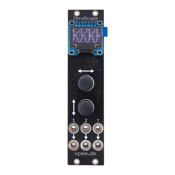
ZeroScope by v pme.de / av500 h ttps://www.muffwiggler.com/forum/viewtopic.php?t= 1 57649 – BOM and build guide, v1.3
Qty Value
Device
1 330R
R0805
1 1.5k
R0805
2 10k
R0805
2 33k
R0805
5 100k
R0805
2 200k
R0805
1 1M
R0805
2 22p
C0805
5 100n
C0805
1 1u
C0805
3 10u
C0805
2
1N5817
DIODE-DO214AC DO214AC
1 MMBT3904
MMBT3904
3 PG331
BLM21PG331
1 AMS1117-3.3
AMS1117-3V3
1 LM4040-2.5
LM4040AIM3-2.5 SOT23
1 MCP602-I/SN MCP602-I/SN
1 STM32F031F6 STM32F031F6
1 OLED
OLED128x64
1 2x3
PINHD-2X3SMT
1 2x8
PINHD-2X8SMT
1 2x5
PINHD-2X5SMT
0 (
L P2985-3.3
)
LP2985
0 (
1 0n
)
C0805
0 (
1 0u
)
C0805
ZeroScope Jacks PCB:
1 2x5
PINHD-2X5
2 EC12E_SW
EC12E_SW
6 WQP-PJ301M THONKICONN
(1) R12, R14, C31 and IC7 STM32F031F6 already populated on PCB
(2) alternatives: 1N5817, LL5817 MELF, SM5817, SS12, also higher rated parts like *5818, *5819, SS13, SS14
(3) you can also use MCP6002, note that
(4) SMT headers delivered with PCB set
(5) v1.2/v1.3 PCB has also pads for a 6-pin SPI OLED, but there are two different versions available!
the supported pinout is: VCC, GND, CLK, MOSI, /CS, D/C - THIS IS UNTESTED, TRY AT YOUR OWN RISK
(6) in very rare cases the ZeroScope might not boot up correctly depending on the power supply used, then increase C6 from 100nF to 1uF.
Package
Parts
R0805
R12
R0805
R13
R0805
R8, R14
R0805
R2, R4
R0805
R5, R6, R7, R15, R16
R0805
R1, R3
R0805
R9
C0805
C2, C4
C0805
C1, C6, C9, C26, C27, C31
C0805
C3
C0805
C10, C25, C28
D1, D2,
( D3 only needed to power from debug header)
SOT23
T1
L0805
L1, L2, L3
SOT223
IC1
IC5
SO08
IC2
TSSOP20
IC7
1X07
OLED
2X03_SMT
DEBUG
2X08_SMT
POWER
2X05_SMT
JP1
SOT23-5L
IC4
(do not install)
C0805
C5
(do not install)
C0805
C8
(do not install)
2X05
JP1
EC12E_SW
E1, E2
WQP-PJ301
IN1, IN2, INT, OUT1, OUT2, OUTT
M
f ake MCP6002
from China have been encountered by me and other diy builders
Description
RESISTOR ( 1)
RESISTOR
RESISTOR (1)
RESISTOR, 1%
RESISTOR, 1%
RESISTOR, 1%
RESISTOR
CAPACITOR, ceramic C0G
CAPACITOR, ceramic (1)(6)
CAPACITOR, ceramic
CAPACITOR, ceramic
30V Schottky diode ( 2)
NPN Transistor, alternatively 2N2222
EMI Suppression Filter BLM21 by Murata
1A 3.3V Low Dropout (LDO) Regulator
2.5V SHUNT VOLTAGE REFERENCE
OP AMP, low voltage, rail to rail, dual (3)
48MHz Cortex M0 CPU (1)
0.96" OLED 128x64,
7 -pin SPI version (5)
PIN HEADER MALE, SMT ( 4)
PIN HEADER MALE, SMT ( 4)
PIN HEADER MALE, SMT ( 4)
LP2985AIM5-3.3/NOPB
CAPACITOR
CAPACITOR
PIN HEADER Female 7mm ( 4)
ALPS Encoder EC12E series with switch or Bourns
PEC11R-4220F-S0024,
20mm shaft length
THONKICON jack
Advertisement

Summary of Contents for vpme.de ZeroScope
- Page 1 VCC, GND, CLK, MOSI, /CS, D/C - THIS IS UNTESTED, TRY AT YOUR OWN RISK (6) in very rare cases the ZeroScope might not boot up correctly depending on the power supply used, then increase C6 from 100nF to 1uF.
- Page 2 ZeroScope by v pme.de / av500 h ttps://www.muffwiggler.com/forum/viewtopic.php?t= 1 57649 – BOM and build guide, v1.3...
- Page 3 ZeroScope by v pme.de / av500 h ttps://www.muffwiggler.com/forum/viewtopic.php?t= 1 57649 – BOM and build guide, v1.3...
- Page 4 ZeroScope by v pme.de / av500 h ttps://www.muffwiggler.com/forum/viewtopic.php?t= 1 57649 – BOM and build guide, v1.3 after soldering the PCB, here are all the parts needed for assembly:...
- Page 5 ZeroScope by v pme.de / av500 h ttps://www.muffwiggler.com/forum/viewtopic.php?t= 1 57649 – BOM and build guide, v1.3 solder the SMT headers, make sure the 10pin header JP1 is centered exactly on the pads, otherwise the jack PCB will not align...
- Page 6 ZeroScope by v pme.de / av500 h ttps://www.muffwiggler.com/forum/viewtopic.php?t= 1 57649 – BOM and build guide, v1.3 insert encoders and jacks into the PCB, add nylon washers...
- Page 7 ZeroScope by v pme.de / av500 h ttps://www.muffwiggler.com/forum/viewtopic.php?t= 1 57649 – BOM and build guide, v1.3 slide front panel PCB onto the jacks and encoders and clamp PCBs together with e.g. a rubber band. check alignment and solder the 10 pin header and the jacks, ...
- Page 8 ZeroScope by v pme.de / av500 h ttps://www.muffwiggler.com/forum/viewtopic.php?t= 1 57649 – BOM and build guide, v1.3 install nuts on 3.5mm jacks. pull the encoders forward so that they sit flush behind the front panel and install the nuts.
- Page 9 ZeroScope by v pme.de / av500 h ttps://www.muffwiggler.com/forum/viewtopic.php?t= 1 57649 – BOM and build guide, v1.3 solder the OLED at the middle pin only and check that it is square and centered, then solder the remaining pins. to install the acrylic cover please remove the protective film, then stack them as pictured and use the provided screws.


Need help?
Do you have a question about the ZeroScope and is the answer not in the manual?
Questions and answers