Table of Contents

Summary of Contents for Indutherm Mini Casting MC16
- Page 1 9 Deforest Street Amityville, NY, 11701 Technical Documentation Mini Casting unit MC16 Romanoff order service for Romanoff consumables: technical service Tel.: +1-631-842-2400 www.romanoff.com service@romanoff.com Keep for future use!
- Page 2 Revision Revision Date chapter Reason responsible 2017-07-24 Edition 2017 2018-01-29 Edition 2018 2019-10-16 last changes This manual has been prepared in good faith by us. Nevertheless, should you find any mistakes or ambiguities, please let us know. Furthermore, we are grateful for comments and suggestions sales@romanoff.com | www.romanoff.com 2019-10-16...
-
Page 3: Table Of Contents
Contents Contents Contents ................... 3 General information ............1–1 Scope of delivery and responsibilities........1–1 Liability, warranty and guarantee ......... 1–1 Responsibility of operating company ........1–1 EC-conformity ..............1–2 Observation of the product ..........1–2 Safety ................... 2–1 Intended use ............... 2–1 Demands on staff, duty for utmost care ....... -
Page 4: Contents
Contents 4.15 Investment material ............4–21 4.16 Investment process ............4–22 4.17 Determination of the powder / water partial quantities ..4–23 4.18 Recommendations for flasks ..........4–24 4.19 Preheating of the flasks ............. 4–24 4.20 Flask temperatures ............4–27 4.21 Collection of spoiled castings .......... -
Page 5: General Information
INDUTHERM Erwärmungsanlagen GmbH don’t take liability for dam- ages caused by faulty protection of power supply and/or wrong con- necting the supplies (protective gas, water, compressed air). There is no guarantee for consumables by INDUTHERM Erwärmung- sanlagen GmbH. Company INDUTHERM Erwärmungsanlagen GmbH can not and will not take responsibility for all consequential damages caused by above mentioned circumstances. -
Page 6: Ec-Conformity
General information Operating company has to ensure unauthorized person has no ac- cess to the system. Maintenance actions may only be done by authorized personnel or by service technicians from manufacturer. EC-conformity Declaration of European Community conformity is attached to this manual. -
Page 7: Safety
The machine has been developed for use in enclosed spaces and for the above-mentioned application. Only original INDUTHERM consumables and spare parts are admit- ted for operation. It is not allowed to change or vary the system in any way. Technical changes need explicit written approval of INDUTHERM Erwärmung-... -
Page 8: Demands On Staff, Duty For Utmost Care
Safety Demands on staff, duty for utmost care Work on and with the machine is allowed to be accomplished by reliable, trained and instructed staff only. Responsibilities for the separate sections have to be regulated clearly which include oper- ation, preparation, service and repair. Only authorized personnel may act at the system. -
Page 9: Concept Of Safety
Safety 2.3.1 Concept of safety Objective is the safety: of the staff against injuries; of the system against damage or standstill and of the environment against endangering. The list of actions taken: deployment of protective equipment like covers and mains switch;... -
Page 10: Safety Markings On The Unit
Safety 2.3.4 Safety markings on the unit A necessary condition for safe dealing with and undisturbed running of the machine is the knowledge of safety instructions and industrial safety regulations. At the machine casing the following safety markings are attached. safety meaning safety... -
Page 11: Safety Marking
Safety Safety marking The following signal words are used in this document which are asso- ciated with safety markings for presentation of possible dangerous situations. Danger! Death, serious body injury or substantial property damage will result if proper precautions are not taken. Warning! Death, serious injury or substantial property damage can result, if proper precautions are not taken. -
Page 12: Safety Advices
Safety Safety advices Check always the condition of the system before you switch on the system. Examine the supply pipes and insulations if there are leaks and damages. Operate the system only if it is in proper and faultless shape. Operate the system never: ... - Page 13 Safety Danger! Risk of burns. If metal is melted without the supply of protective gas, can cause a flash fire or explosion when opening the bell. Melt at temperatures above 500 °C always with protective gas. Use as a protective gas exclusively argon or nitrogen Danger! Danger because of touching parts conducting voltage.
- Page 14 Safety Warning! Danger of explosion. Dripping liquid metal can’t be excluded. The set-up place (table) and the floor beneath the system should be made of non-flammable material. As well there shouldn’t be stored inflammable materials within a radius of 5 metres. Attention! At crucible temperatures over 100 °C the cooling water supply must be switched on.
-
Page 15: Residual Risks
Safety Caution! Observe regulations for the mains supply written from the responsible electric power supply company, the associa- tion VDE and the local electric power station. Inappropriate connecting can lead to injuries and dam- ages of the machine. Caution! Danger for health because of inhalation of fibre particles. ... -
Page 16: Technical Data
Technical Data Technical Data MC16 15 cm (ceramic crucible) Crucible volume (1) 10 cm³ (with graphite inlay) Pressure range in melting chamber in bar -1 to 2 Crucible temperature in °C max. 2000 Melting performance in kW Mains supply 230 V, 50 or 60 Hz Fuse protection in A 4.45 Abduct current in mA... -
Page 17: Description Of The System
System description Description of the system Components of the system The system consists of several modules assembled in one housing. Inside the housing there are: mains cable, microprocessor controlled induction generator DM-type, middle-frequency transformer, oscillating circuit capacities and ... -
Page 18: Schematic Representation
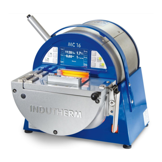
System description Schematic representation Figure 1: overall view Position Description Function tilting handle with Due to movement to the right the machine will lock cast. inductor housing The melting and casting process takes place here. control buttons. Control the casting process. See ch. 4.6. LCD screen See chapter 4.5 top plate with... -
Page 19: Connections On The Backside
System description Connections on the backside Figure 2: backside of the mini-casting machine Position Description Function of the connection vacuum filter filters the vacuum Gas out gas outlet Protective gas input for protective gas Vacuum connection for external vacuum pump Water In input for cooling water Water Out... -
Page 20: Set-Up In The Vacuum Chamber
System description Set-up in the vacuum chamber Figure 3: set-up with graphite crucible Position Description Function thermocouple type S Allows a temperature measurement up to 1400 °C. ceramic crucible with In this crucible the graphite contains the heat and trans- graphite inlet fers the energy to the metal. -
Page 21: Front Panel Display
System description Front panel display 4.5.1 MC16 screen when starting the machine Figure 5: screen with mains supply on Temp. Prog. °C 0010 0.00 Temp. InduTest 1 Prog. Program Manual Power Prog. Edit Setup page Display in the middle section: 22 °C actual temperature 0010 °C... -
Page 22: Mc16 Modify Program Screen
System description 4.5.2 MC16 modify program screen Figure 6: program 0018 Program InduTest 1 parameter Λ 0010 °C Temperature 0100 % Heating power middle section with 0000 Washing before heat program parame- 0000 Washing while heat Manual Melt. press. start –... -
Page 23: Mc16 Modify System Parameter
The ad- justed values should be changed with care and usually after consulta- – 000: 00002 (TC N) tion with the Indutherm service staff. Temp. Sensor 0 Type Haupt- Serv. Display-functions: 000: 00002 Selected parameter: 000. -
Page 24: Mc16 State-Level (Service Info Page 1 + 2)
System description 4.5.4 MC16 State-Level (Service Info Page 1 + 2) If you press “Serv.” in system parameter menu, you’ll see software ID, generator no. and machine no. Figure 8: Service-Info-Page 1 Serv. Service Info Page 1 Print 801.0117 SW-ID.Build (Jul 26 2016) (08:54:57) DM0777 Generator No. -
Page 25: Front Panel Buttons
System description Front panel buttons Figure 10: front panel From left to the right Button Function Stop Stops active program. 6 push buttons left Function of these buttons you can see in display. See chapter and right from display 4.5.2 too. Generator Starts and stops heating with induction generator outside the automatic mode. -
Page 26: Functional Description
(eg commercially available copper or silver), de- gassing of the molten metal under vacuum is possible. The INDUTHERM mini casting machine MC16 is suitable to cast all kind of metals into moulds or into investment flasks. Exceptions are dental alloys and very reactive alloys like magnesium. - Page 27 System description All functions are linked with the turning of the chamber: immediately after pouring metal into the flask, over pressure comes automatically. As mentioned before, a pressure impulse on top of liquid metal, while inside there is still a vacuum, makes the good form-filling of this system.
-
Page 28: Casting Programs For Mc16 (05.12.2016)
System description Casting programs for MC16 (05.12.2016) Figure 11: predefined casting programs MC16 Material Silver Yellow Test 1 Test 2 Plati- Stain- Palladi- gold 18k less um 950 steel CrCo Crucible Graphite Graphite Ceramic Ceramic Ceramic Ceramic Ceramic Temperature read- Thermo- Thermo- without... -
Page 29: Direct Induction Heating In Ceramic Crucible
System description Direct induction heating in ceramic crucible Direct induction melting is necessary on metals with high temperature melting points, such as Pt., steel etc. High temperatures do not allow use of graphite crucibles because of quick burning under standard atmosphere. Also, direct induction melting is necessary on metals, which reacts unwanted with graphite. - Page 30 System description At direct induction melting please notice following hint: If a too voluminous piece of metal will be added to an already molten metal, molten metal can “freeze”, it becomes solid again. If this form-fitting metal now is heated-up again, it expands can disrupt the crucible.
-
Page 31: Temperature Control
System description 4.10 Temperature control To use the temperature controller a thermocouple type N article no 13400010 up to 1300 °C (parameter P.000 - must be set to 0002) type S article no 13000030 up to 1400 °C (parameter P.000 - must be set to 0001) has to be connected to the socket inside the casting chamber. - Page 32 System description Attention: Do not use a thermocouple in direct heating process! Energy will melt thermocouple! If you use graphite crucible and thermocouple the output power must not exceed 50 % (1.7 kW). Otherwise the temperature overshoot is too high and will burn the thermocouple. sales@romanoff.com | www.romanoff.com 2019-10-16 4–16...
-
Page 33: Tree Making
System description 4.11 Tree making Pieces made of wax/plastic must be placed in “tree”-shape. This is done by a small sol- dering needle + wax wire at (wax-) center sprue. This main sprue is fixed in the rubber base, the diameter of the rubber base is according to the diameter of the flask. On bigger trees for bigger machines there is a main wax sprue (ø... -
Page 34: To Find Out The Weight Of The Metal
System description 4.12 To find out the weight of the metal All rubber bases must be determined on a scale. Write exact weight on this rubber bases by a felt pen. After mounting the tree, take the total weight. Deduct the rubber base weight from the total weight = net wax weight. -
Page 35: Using Already Cast Material
System description 4.13 Using already cast material Because of high costs casters do not like to use every time fresh alloy. For some alloys customers mix “second hand metal” up to 50 %, mainly Au, Ag based alloys. Please pay attention to following: ... - Page 36 System description Platin Set heating power to 3.5 kW (100%). Use the special ceramic crucible for Platinum. Put metal into the (cold) cruci- ble. Push “Start” once for heating, set in flask and lock chamber. Push “Start” second time to start the vacuum. Full vacuum is reached inside the gypsum in about 30 seconds (see timer).
-
Page 37: Investment Material
System description 4.15 Investment material Generally, there are three types of investment: Gypsum-bonded investment materials for metal temperatures up to 1250 °C. (Flask tem- perature up to 730 °C) These are standard investment materials for gold, silver, bronze, etc. These investment materials are stirred with water and the investment is easy to re- move by quenching in water. -
Page 38: Investment Process
System description 4.16 Investment process Investment process means, that powder is mixed for a certain time with water in a special ratio into slurry and filled into a flask. This stirring can be done in an open bowl with a spatula. However, air is also introduced = bubble formation in the investment material = bubbles on the surface of the wax plastic parts after embedding. -
Page 39: Determination Of The Powder / Water Partial Quantities
System description 4.17 Determination of the powder / water partial quantities Determining amount of powder per flask this formula is helpful: Volume of flask in cm³ x 1.4 = amount of powder in grams For example flask ø 8 x 8 cm r²... -
Page 40: Recommendations For Flasks
System description 4.18 Recommendations for flasks For standard MC16 flasks there are some recommendations: gypsum bonded investment powder like Goldstar XL, XXX, Kerr Satin Cast 20 etc. 100: 40 powder:water flask size investment powder water in ml mixing time in in grams min:sec Ø... - Page 41 System description With phosphate-bonded investment you can go immediately to casting tempera- ture. The flask can be heated up in 2 hours from 300 °C to e.g. 900 °C. (equivalent to a ramp of 5 °C/min) and keep there 30 to 60 minutes (smaller flasks less time, bigger flasks more time.
- Page 42 System description But it is also possible to push this cycle. Here a recommendation of a RAPID firing cycle: Figure 20: Rapid firing cycle Casting temperature Time in h RAPID firing cycle for flasks MC16 gypsum bonded investment material Caution: In case of a “gentle”-firing cycle all amenities of the investment material are pre- vented from damage.
-
Page 43: Flask Temperatures
System description Standard-burnout-cycle phosphate bonded: (from investment to casting 5 hrs) Resting time after investment 1 hr, in 1 hr (5 °C/min) to 300 °C, holding time 30 min, in 2 hrs (5 °C/min) to 900 °C, holding time 30 min (with flasks Ø 65 mm x 80 mm and Ø 80 mm x 80 mm should the holding time be extended to 60 min). -
Page 44: Collection Of Spoiled Castings
System description 4.21 Collection of spoiled castings Horizontal flashing or finning Figure 21: horizontal flashing or finning Cause Remedy Incorrect powder / water ratio (too much Using correct amount of water (espe- water). cially important with vacuum investing machines). - Page 45 System description Bubbles - Complete Spheres Figure 23: bubbles - complete spheres Cause Remedy Investment too thick. Too little water. Use correct powder / water ratio. Vacuum pump/ tank faulty. Ensure equipment is regularly serviced and adequate for the task. ...
- Page 46 System description Water marking Figure 25: water marking Cause Remedy Incorrect powder / water ratio (too much Use correct amount of water (especially water). important with vacuum investing ma- chines). Work time of investment not used up. Ensuring the work time is used up and slurry temperature is 20 –...
- Page 47 System description Rough Surfaces Figure 27: rough surfaces Cause Remedy Rough waxes. Use less release agent on the rubbers. This can be caused by excess of tal- cum. Use only a trace of talcum. Never use silicon spray. ...
- Page 48 System description Incomplete castings Figure 29: incomplete castings Cause Remedy Metal or flask too cold. Please increase casting temperature. If the metal or mould is too cold, the metal will freeze before complete- ly filling the mould. ...
- Page 49 System description Blisters, spalling Figure 31: blisters, spalling Cause Remedy Flask has been heated too Do not exceed 150 ºC during de-wax. Wax will rapidly during de-wax. boil and erode investment surface. Flasks overheated during burn Ensure maximum burn out temperature does not out.
-
Page 50: Transport
Transport Transport Danger! Injuries because wrong transport. Take care of the right position using transport device to avoid tilting of the system. Please wear appropriate personal protective equipment (PPE). Let do transportation only by trained personnel. There is no guarantee for damages because of failure to comply transport regulations. -
Page 51: Mounting And Commissioning
Mounting and commissioning Mounting and commissioning Safety advices for mounting Danger! Only experts may work at the electrical equipment. Danger! Observe the mains supply to requirements of the local electricty sup- ply company, the VDE and the local electricity company. Use always the 2-pin power plug with safety contacts for connecting the system to the mains supply. -
Page 52: Apply Supply Connections
Mounting and commissioning Apply supply connections 6.3.1 Power supply The electrical connection may only be performed by a specialist. Note the information specified on the nameplate rated voltage or frequen- cy. The single-phase power supply may differ for max. +/- 10% from the rated voltage. -
Page 53: Protective Gas
Mounting and commissioning 6.3.3 Protective gas The protective gas only nitrogen or argon may be used with a purity status of at least 99.9 %. The supply is effected via a compressed air hose having an inner diameter of 6 mm. The inlet pressure must not exceed 8 bar. -
Page 54: Rs232 For Service
Mounting and commissioning 6.3.6 RS232 for service At this plug behind a black cover our modem (item no. 71000320) or our serial cable (50500060) can be connected for service issues. ̉ L AN, Ethernet or RJ-45 connector for service 6.3.7 Behind a black cover, you’ll find this plug to connect the machine to a network (LAN-local area network). -
Page 55: Operation
Operation Operation Safety advices for operation Caution! Examine all consumables, insulations and hoses before switching on. Check for damages and cleanliness, especially crucible and glass shield. Operate the system only when it’s free of damages. Warning! Risk of burning on hot surfaces and hot metal (until ~ 2000 °C). -
Page 56: Changing Casting Parts
Operation Changing casting parts Attention! Switch off the machine at mains switch, when you change consum- ables, like e.g. crucible. 7.2.1 Removal > Open the top plate of the casting chamber. > Remove “old crucible”. Check glass inductor shield. 7.2.2 Mounting >... -
Page 57: Recommendation For A Casting Process
Operation Recommendation for a casting process Figure 37: further suggestions of casting programs Suggestions Material Yellow gold 14k Crucible Graphite Temperature reading Thermo- couple Program No. Temperature °C 1080 Heating power 0050 Washing before heating 0000 Washing while heating 0001 Melting pressure start Manual Melting pressure... -
Page 58: Error Diagnosis
Low genera- toroutput Additional error messages see software-documentation. Service If you need technical support from company INDUTHERM Erwärmungsanlagen GmbH, we’d like to have following information with first contact: Service No. M19999 on the left front side of machine or ... -
Page 59: Maintenance
Maintenance Maintenance Safety advices for repair and maintenance For reliable use and highest work accuracy use is regular mainte- nance and service of your system a prerequisite. The necessary working steps are summarized in this chapter and have to carry out in time. -
Page 60: Maintenance Schedule
Maintenance Warning! Slipping on the floor in the area around the plant, if lubricants or sol- vents were spilled. Clean the dirty floor immediately! Discard the cleaning cloths in the collecting means made available. Maintenance schedule Follow the maintenance schedule to obtain the functionality of the system. -
Page 61: Repair
Maintenance Every year Cooling water system with about 25 % citric acid rinse for about an hour. Then system thoroughly flush with clean water and check for possible leaks. This cleaning-supply cycle is highly de- pendent on the hardness and cleanliness of the cooling water. ... -
Page 62: Dismantling And Cleaning Up
Dismantling and cleaning up Dismantling and cleaning up Warning! Permanent skin damages after touching lubricant or sol- vent of every description (long term effects). Avoid touching lubricants, solvents and coolants. Wash the sprinkled skin parts thoroughly. Wear protective gauntlets when using lubricants, solvents and coolants. -
Page 63: Annexe
Annexe Annexe 10.1 List of figures Figure 1: overall view ..............4–2 Figure 2: backside of the mini-casting machine ......4–3 Figure 3: set-up with graphite crucible ..........4–4 Figure 4: types of crucibles ............4–4 Figure 5: screen with mains supply on ........... 4–5 Figure 6: program parameter ............ - Page 64 Annexe Figure 36: crucible and glass inductor shield ........7–2 Figure 37: further suggestions of casting programs ......7–3 Figure 38: safe handling of lock ............. 7–3 Figure 39: backside vacuumfilter ............. 8-2 Figure 40: connection diagram ............10-7 Figure 41: inductor chamber ............10-8 Figure 42: contact form webshop ..........
-
Page 65: Ce Declaration Of Conformity
Annexe 10.2 CE Declaration of conformity Manufacturer: INDUTHERM Erwärmungsanlagen GmbH Brettener Str. 32, 75054 Walzbachtal, Germany Product type: Mini-casting machine Machine type: MC16 Serial number: 16265 or higher Authorized to sign: Peter Hofmann We herewith declare that the machine named above corresponds to the essential safety and health requirements of the following EC directives because of its design and construction in the version which we have placed on the market. - Page 66 The declaration of conformity relates only to the machine in the state in which it was placed on the market; Parts and / or retrospective interventions carried out subsequently by the end user remain unaffected. The test protocols are stored at INDUTHERM for 10 years. city/date/signatory: Walzbachtal/2019-10-16/Peter Hofmann, chairman sales@romanoff.com | www.romanoff.com...
-
Page 67: Connection Diagrams
Annexe 10.3 Connection diagrams Figure 40: connection diagram sales@romanoff.com | www.romanoff.com 2019-10-16 10-7... -
Page 68: Cut Diagram Of The Replacement Parts
Figure 41: inductor chamber Consumable – and spare parts list 10.5 INDUTHERM is now using only machine specific spare parts list, which contain all the information for your machine. At following page, the spare parts list for this machine will start. -
Page 69: Software Documentation With Error Messages
Software-Documentation starts at next pages. The label of the bilingual documentation is “generator_documentation_80000xxx_customer_DM_F_PM_Gen.pdf”. xxx is the software state. This is also valid for 801.00xxx software in your machine since 2018. Please note: At our Internetpage http://www.indutherm.de/webshop you can get after registration access to important data. Figure 42: contact form webshop...
Need help?
Do you have a question about the Mini Casting MC16 and is the answer not in the manual?
Questions and answers