Table of Contents
Advertisement
Quick Links
Matrix Maxi
Installation, Operation & Maintenance
Instructions
Please leave this instruction booklet with the end user as it contains important
guarantee, maintenance and safety information
Read this manual carefully before commencing installation.
This manual covers the following products:
Matrix Maxi 180D
Pt. No. 121-1021
Matrix Maxi 280D
Pt. No. 121-1022
CE compliant product
2
Advertisement
Table of Contents

Related Manuals for Altecnic Matrix Maxi

Summary of Contents for Altecnic Matrix Maxi
- Page 1 Please leave this instruction booklet with the end user as it contains important guarantee, maintenance and safety information Read this manual carefully before commencing installation. This manual covers the following products: Matrix Maxi 180D Matrix Maxi 280D Pt. No. 121-1021 Pt. No. 121-1022...
-
Page 2: Table Of Contents
The tank includes an AB air gap for category 5 fluid isolation (BS EN 1717). APPLICATION The Matrix Maxi range is designed to provide initial system fill and intermittent water top up to compensate for intermittent losses in system pressure in heating and cooling systems in commercial or industrial applications. - Page 3 WARNINGS: This appliance must not be used for any other application without the written consent of Altecnic Limited. This appliance can be used by children aged from 8 years and above and persons with reduced physical, sensory or mental capabilities or lack of experience and knowledge...
-
Page 4: Checklist
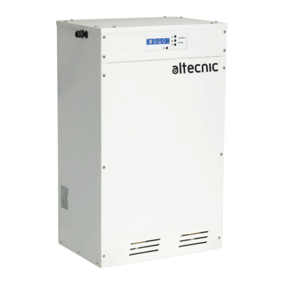
CHECKLIST IMPORTANT: With the appliance removed from its packaging check for any damage prior to installation. If any damage is found contact Altecnic Ltd within 24 hours of receipt. Electrical rating plate and serial number Inlet Overflow Outlet Fig. 1... -
Page 5: Important Facts - Read Before Commencing Installation
READ BEFORE COMMENCING PUMP INSTALLATION A Water storage capacity. 1.11 The Matrix Maxi has a usable water volume of approximately 18 litres; the length of time the Matrix Maxi takes to pressurise a system will be dependent on:- The pressure differential between the cold fill and set pressures and also the refill rate of the tank 1.12 Ensure the pumps are primed as described in the priming section before starting, to... -
Page 6: Location
2.16 Supply inlet pressure: The water supply inlet pressure must not exceed 7 bar. 2.17 Ambient temperature: The Matrix Maxi must be sited in a location where the ambient temperature does not drop below 4 °C or exceed 40 °C. - Page 7 2.20 Isolating valves: Separate system isolating valves (non-restrictive) must be fitted to allow easy service of the Matrix Maxi. Isolating valves must be mounted where specified to allow the system isolation and removal of the Matrix Maxi if needed. See Section 4.15 for installation details.
-
Page 8: Key Features
3 KEY FEATURES 3.11 The Matrix Maxi comprises of the following main components:- 1. Cabinet – The cabinet of the Matrix Maxi houses the water break tank, controller, pumps and pipework. the cabinet is manufactured in corrosion resistant stainless steel. -
Page 9: Installation
2. Ensure the floor surface on which the Matrix Maxi is located is flat and level. 3. If possible locate the unit against a wall for added stability. 4. If the Matrix Maxi is located in an area that might be subjected to flooding, mount the Matrix Maxi on a raised plinth. - Page 10 6. The Matrix Maxi should be connected to the system return header along with the expansion vessels as specified in BS 7074. See Fig. 5.
-
Page 11: Electrical Installation
Reference should be made to the relevant regulations concerning this subject to ensure compliance. 5.19 Connections: The Matrix Maxi must be connected to a dedicated fused spur via a lockable isolator to avoid unauthorized disconnection. 5.20 The electrical connection must be made adjacent to (not behind) the Matrix Maxi to allow disconnection of the electrical supply should the pump module need to be removed for service or maintenance. - Page 12 5.22 Boiler interlock safety function: The Matrix Maxi is fitted with a volt free contact specifically assigned for boiler/chiller shut down in the event that the Matrix Maxi detects system pressure above the Hi alarm pressure or below the Lo alarm pressure.
- Page 13 Circuits connected to the relays are limited to 5 Amps, 230 V a.c. maximum. The Installer MUST fit a 5 Amp fuse in the circuit to the alarm relay to protect the Matrix Maxi from damage. Boiler Interlock Common Alarm...
- Page 14 4) Re-insert connector into the correct location on the control board and route the cable to the back of the Matrix Maxi and exit the cabinet via one of the 20 mm holes and a suitable cable retention and sealing system to either the left or right hand side.
-
Page 15: Commissioning
6.14 Expansion vessel setting: To set or check the expansion vessel charge pressure the lock-shield valve between the Matrix Maxi and the vessel must be closed and the vessel drained using the drain valve. A suitable gauge should be used to check the charge pressure. - Page 16 LCD display. On the front of the Matrix Maxi a green ‘power on’ light will be displayed whilst the unit is powered. If an alarm or error is raised the red ‘Error’ light will be displayed.
- Page 17 Test menu (pass code protected) see Section 6.20. 6.17 Initial display On start up, and during operation, if the Matrix Maxi has had no button inputs for 1 minute, a home screen (see Section 7.11) will be displayed with system pressure, tank water level, any active alarm and any pump that is operating at the time.
- Page 18 (3) is reached on falling pressure. Adjustable from 3 Pump start delay to 120 seconds, pre-set to 3 seconds. Increasing this time will reduce un- wanted Matrix Maxi operation during rapid system pressure fluctuations (circulator pump starts) 6.20 Test Menu...
- Page 19 6.21 Pre-set values The Matrix Maxi will be delivered with the following pre-set values:- 6.22 Setting menu Set Pressure 2 bar Differential 0.2 bar Hi Alarm 2.5 bar Lo Alarm 1.3 bar System fill Run activity high 1000 6.23 Advanced setting menu...
- Page 20 6.24 Controller menu diagram 18 March 2019 Power ‘on’ Home screen Start up screen Delay (logo) System pressure Enter pass display code (If set) Error display Advanced menu System fill status display Pump run on delay Pump activity display Pump start delay Pump run time display...
- Page 21 Home screen will be displayed. The Matrix Maxi will run briefly and then turn off after a pre-set run on time. Due to the small size of the isolated system the Matrix Maxi will signal a Hi pressure error and the red error light will illuminate on the front of the Matrix Maxi, this is normal.
-
Page 22: Operation
2.10 bar FULL Fig. 18 A green ‘Power on’ light will be displayed on the front of the Matrix Maxi. More detailed information is available by scrolling up or down to display:- System pressure System errors i.e. pump fail, low or high pressure or none. - Page 23 3-5 seconds to avoid the pump(s) from seizing due to inactivity. 7.13 Fault codes: If there is a system fault, a red light will be displayed on the front of the Matrix Maxi. If the fault/alarm is cleared the red light will go out.
-
Page 24: Maintenance
8 MAINTENANCE 8.11 Routine maintenance & service checks: Every 6 & 12 months (see Section 12 - service log) the Matrix Maxi should be inspected for:- Damage to the electrical supply cable. Damage to the inlet and outlet flexible hoses. -
Page 25: Environment Protection
9. Open the Matrix Maxi outlet isolation valve and monitor the Matrix Maxi to ensure there is no leaks as the system pressure increases. 10. Check all the pre set values on the Matrix Maxi to ensure they are still suitable for the system (after maintainance/modification) 9 ENVIRONMENT PROTECTION Your appliance contains valuable materials which can be recovered or recycled. -
Page 26: Technical Specification
10 TECHNICAL SPECIFICATION Matrix Maxi 180D Matrix Maxi 280D Pump Model 121-1021 121-1022 Guarantee 2 year General Approvals Features Sealed system capacity Up to 300,000 litres Mounting Floor mount Pump control system ü ü Pumps Intelligent control interface ü ü... - Page 27 Filled weight 52 Kg 63 Kg Altecnic Ltd reserve the right to amend the specification without notice. 10.11 Noise: The equivalent continuous A-weighted sound pressure level at a distance of 1 metre from the pump does not exceed 70 dB(A).
-
Page 28: Trouble Shooting
Error Code Probable Cause Recommended Action No power to Matrix Ensure the green light is on the front of the Matrix Maxi, check fuse. Pump(s) not Maxi starting Depress float valve to varify water is filling tank, check water level and supply. -
Page 29: Product Log
12 PRODUCT LOG 12.11 Customer Details Customer/company name Site address Date 12.12 Equipment details System volume m Expansion vessel(s) fitted & pre- charge pressure Boiler(s) fitted 12.13 Commissioning record Date commissioned Company Engineer System set pressure Differential pressure Hi alarm set pressure Lo alarm set pressure 12.14 Service Log Service No. - Page 30 Service No. 2 Date Engineer name Company name Tel. No System pressure bar Differential pressure bar Check 6 months 12 months Condition of wiring ü ü Condition of hoses ü ü Evidence of leakage ü ü Controller fault codes ü ü...
- Page 31 Service No. 4 Date Engineer name Company name Tel. No System pressure bar Differential pressure bar Check 6 months 12 months Condition of wiring ü ü Condition of hoses ü ü Evidence of leakage ü ü Controller fault codes ü ü...
-
Page 32: Guarantee
We are confident this product will provide many years of trouble free service as all our products are manufactured to the very highest standard. The Altecnic Matrix Maxi is guaranteed to be free from defects in materials or workmanship for 2 years from the date of purchase. - Page 33 NOTES - 33 -...
- Page 34 NOTES - 34 -...
- Page 35 NOTES - 35 -...
- Page 36 Altecnic Ltd in any form, without prior written consent of Altecnic Ltd.
Need help?
Do you have a question about the Matrix Maxi and is the answer not in the manual?
Questions and answers