
Subscribe to Our Youtube Channel
Related Manuals for Elite EC612

Summary of Contents for Elite EC612
- Page 1 Elite Robot User Manual Doc. Name: EC612 User Manual Suzhou Elite Technology Co. Ltd. www.elibot.cn April 3, 2020...
- Page 2 Suzhou Elite Robot Co., Ltd. shall assume no liability for any errors which will occur in the manual probably. Suzhou Elite Robot Co., Ltd. shall assume no liability for the accident or indirect injury as a result of using this manual and the product mentioned herein.
-
Page 3: Table Of Contents
Doc No.:T202001006 www.elibot.cn Contents Contents ............................. 2 Preface ............................5 Product Composition ......................6 More Information ....................... 6 Chapter 1 Safety ......................... 7 1.1 Profile ........................... 7 1.2 Safety Warning Symbols ....................7 1.3 Safety Cautions ......................9 1.3.1 Overview ......................9 1.3.2 Usage Notice ..................... - Page 4 Doc No.:T202001006 www.elibot.cn 7.2 Robot Power-on ......................34 7.2.1 Preparations before power-on ................. 34 7.2.2 System power-on ..................... 35 7.3 Robot Shutdown ......................35 Chapter 8 Electrical Interface ....................36 8.1 Overview ........................36 8.2 Electrical Warnings and Cautions ................36 8.3 Controller I/O ......................
- Page 5 Doc No.:T202001006 www.elibot.cn 9.6.2 Variables ......................95 9.6.3 IO ........................97 9.6.4 Motor ....................... 98 9.6.5 Operational Monitoring ................100 9.7 Convenient Functions ....................100 9.7.1 Key Combination Function ................100 9.7.2 Multi-Window Function................101 9.8 System Setup ......................101 9.8.1 Tool Coordinates Setting ................
-
Page 6: Preface
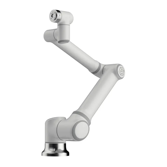
Thank you for purchasing and using the light 6-degree-of-freedom (DOF) collaborative robot EC612 developed by the company. The EC612, as one of the ELITE modular collaborative robot series, is an intelligent light 6-DOF modular collaborative robot launched by Suzhou Elite Robot Co., Ltd., with a payload of 12kg.The ELITE collaborative robot series takes a joint modular design, and uses a... -
Page 7: Product Composition
Doc No.:T202001006 www.elibot.cn Product Composition The detailed outbound list of one set of complete EC612 robot is shown in the table below. Name Quantity Robot body Control box including teach pendant Power cord Base (Optional) User manual (disk) Thin-walled wrench More Information www.elibot.cn... -
Page 8: Chapter 1 Safety
Doc No.:T202001006 www.elibot.cn Chapter 1 Safety 1.1 Profile This chapter introduces the safety principles and specifications that should be followed when operating the robot or the robot system. The integrator and the user must read this manual carefully, and need to mainly master and strictly comply with contents with warning labels. As the robot system is complicated and dangerous, the user must fully understand the risk of operation, strictly comply with and implement the specifications and requirements in this manual. - Page 9 Doc No.:T202001006 www.elibot.cn SAFETY CAUTION: Indicating an imminently hazardous situation which, if not avoided, could result in casualties or serious injury. Indicating a potentially hazardous electrical situation which, if not avoided, could result in personnel injury or serious damage of the equipment. Indicating a potentially hazardous situation which, if not avoided, could result in personnel injury or serious damage of the equipment.
-
Page 10: Safety Cautions
Doc No.:T202001006 www.elibot.cn 1.3 Safety Cautions 1.3.1 Overview This manual includes the safety measures of protecting the user and preventing the machine from damage. The user must read all relevant descriptions in the specification and be fully familiar with the safety cautions. In this manual, we shall try to describe various situations. However, it seems impossible to record all the cases that cannot be done in accordance with so many possibilities. - Page 11 5. The brake is installed in the EC612 joint module, to maintain the pose of the robot arm when the power is switched off. Do not artificially switch the power supply system on and off frequently.
- Page 12 The authorized reassembling of the robot shall be done in accordance with all relevant service manuals of the latest versions. If the robot is changed or altered in any way, Suzhou Elite Robot Co., Ltd. will not take any responsibility.
-
Page 13: Personnel Safety
1. All operating personnel using the robot system should receive the training and pass the training courses hosted by Suzhou Elite Robot Co., Ltd. The user should ensure to fully grasp the safe and normative operational process and have the qualification of operating the robot. For detailed training, please contact with the company by E-mail: support@elibot.cn. -
Page 14: Liabilities And Specifications
For reference to applicable standards and legal guide, please visit the website: www.elibot.cn. All safety-related information contained in this manual shall not be regarded as the warranty of Suzhou Elite Robot Co., Ltd. Even though all safety instructions are followed, the personnel injury Page 13 of 130... -
Page 15: Danger Identification
Suzhou Elite Robot Co., Ltd. strives to ensure accuracy and reliability of the contents in this manual, but takes no responsibility for any errors or missing information herein. -
Page 16: Intended Use
The ELITE robot must be used only under the specified condition. For specific information about the relevant operating environment and operating conditions, please refer to the appendix. -
Page 17: Handling Of Emergency Situations
IEC 60947-5-5. The EC612 is equipped with the emergency stop buttons on the control box and the teach pendant. The button should be pressed only when meeting the dangerous situations or emergencies, as shown in following figure. -
Page 18: Resuming From The State Of Emergency
Doc No.:T202001006 www.elibot.cn 1.7.2 Resuming from the state of emergency All emergency stop equipments in form of button have "Locking" function. The "Lock" must be unlocked, as to end the emergency stop state of the equipments. The "Lock" may be unlocked by rotating the emergency stop button. Resuming from the emergency stop state is a simple and important step which can be operated only when the danger of the robot system is eliminated completely. - Page 19 Doc No.:T202001006 www.elibot.cn robot arm. The function may reduce the damage as a result of impact, and the risk assessment must be implemented when used for other purposes. Page 18 of 130...
-
Page 20: Chapter 2 Carrying And Cautions
1. Make sure that your back or other parts of the body are not overloaded when raising the equipment. 2. All regional and national guides should be followed. Suzhou Elite Robot Co., Ltd. shall not be responsible for damage generating during transportation . -
Page 21: Chapter 3 Maintenance, Repair And Disposal
Maintenance must be implemented by authorized system integrator or Suzhou Elite Robot Co., Ltd.When the parts are returned to Suzhou Elite Robot Co., Ltd., operation should be implemented in accordance with the provisions in the service manual. -
Page 22: Disposal
4. The control box does not have a part that the end-user can repair by himself. If maintenance or repair services are needed, please contact with the dealer or Suzhou Elite Robot Co., Ltd. 3.2 Disposal The ELITE robot must be disposed in accordance with the applicable national laws and regulations and the national standards. -
Page 23: Chapter 4 Quality Assurance
In case of defects of the equipment which is out of warranty, Suzhou Elite Robot Co., Ltd. shall not be responsible for any damage or loss caused therefrom, such as loss of production or damage due to other production equipments. - Page 24 As for any other explicit or implied warranties or liabilities including, but not limited to, any implied warranty for marketability or specific use, Suzhou Elite Robot Co., Ltd. shall not bear the related liability to guarantee. In addition, Suzhou Elite Robot Co., Ltd. shall not be responsible for the related liabilities in allusion to any form of indirect damage or consequence generated by the related product.
-
Page 25: Chapter 5 Robot Hardware Composition
Chapter 5 Robot Hardware Composition Figure 5-1 EC612 robot system As shown in Figure 5-1, the EC63 collaborative robot system mainly consists of the robot body, the control box (multiple types of the control boxs are optional), the base and the teach pendant. The robot body imitates the arm of human body, and totally has six rotating joints and each representing one degree of freedom. - Page 26 Doc No.:T202001006 www.elibot.cn Figure 5-2 Robot joints The control box is the main part of the control system of the EC63 collaborative robot. Please refers to the instructions of the control box in the user manual for the components inside the control box.
-
Page 27: Chapter 6 Robot Installation
Description of installation of the additional device: if the additional components, such as the cable which is outside the range that Suzhou Elite Robot Co., Ltd. should provide, are integrated into the industrial robot, it is the user’s responsibility to ensure that these components are completely unaffected and the safety functions would not be affected. -
Page 28: Workspace Of The Robot
Figure 6-1 Mechanical dimensions diagram of the EC612 robot, with unit of mm 6.3.2 Range of motion of the robot Figure 6-2 shows the range of motion of the EC612, namely, a sphere with a radius of 1304mm except the cylindrical space directly above and directly below the base. When choosing the... -
Page 29: Robot Installation
Doc No.:T202001006 www.elibot.cn Figure 6-2 Schematic diagram of workspace of the robot 6.4 Robot Installation The robot has the 360° pose self-adaptive function at the installation location, and is compatible with installation, hoisting, wall mounting and other specific installation ways on the base, as shown in Figure 6-3. - Page 30 Doc No.:T202001006 www.elibot.cn mechanical dimensions are shown in Figure 6-4. Figure 6-4 Dimensions of installation holes on the base, with unit of mm 1. When installing on the base, the robot should closely contact with a contact surface of the base, and the surface should be sufficient to bear at least 3500Nm torsional force in a selected installation direction of the base joints and a weight of at least 100kg.
-
Page 31: Installation Of The End/Tool Effector
Doc No.:T202001006 www.elibot.cn Reverse installation 1754N± 360N 1754N± 2594N Vertical installation 1554N± 360N 1554N± 2594N 6.5 Installation of the End/Tool Effector The tool flange has four M6 threaded holes and one Ф6 positioning hole, in this way the clamp may be conveniently installed and connected to the robot end. The mechanical dimensions of the tool flange are shown in Figure 6-5. - Page 32 Doc No.:T202001006 www.elibot.cn WARNING 1. The load conditions should fall within the scope shown in the chart. 2. The payload shown in the diagram indicates a maximum payload which should not exceed a maximum weight shown in the diagram under any circumstances. 3.
-
Page 33: Chapter 7 Quick Start
Chapter 7 Quick Start 7.1 Installation 7.1.1 Robot installation Take the ELITE robot out of the packing box and install it on the base. Please refer to Chapter 6 Robot Installation for the specific installation instructions. 【NOTES】 1. The control box should be placed on the ground horizontally. A 50 mm clearance should be reserved on each side of the control box to ensure smooth air circulation. -
Page 34: Connection Of The Control Box To The Mains Supply
Doc No.:T202001006 www.elibot.cn rectangular plug into the control box. Pay attention to the insertion direction, and lock the connector after tight insertion, as shown in the following figure. Figure 7-2 Connection of the robot cable to the control box 7.1.2.2 Connection of the control box to the mains supply There is a heavy-load rectangular plug at the end of the mains cable of the control box. -
Page 35: Robot Power-On
Doc No.:T202001006 www.elibot.cn Figure 7-3 Diagram of the power interface of the control box 【DANGER】 1. Please make sure that the robot is grounded correctly (electrical connection to ground). The grounding conductor should have at least rated current of the highest current in the system. 2. -
Page 36: System Power-On
Doc No.:T202001006 www.elibot.cn • The mode selection button is positioned at the correct position. • Make sure the robot would not contact with the surrounding personnel and the equipment. System power-on 7.2.2 7.3 Robot Shutdown Shutdown sequence: turn off the power supply of the robot and the teach pendant first; then turn off the power supply of an I-series control box. -
Page 37: Chapter 8 Electrical Interface
DOC No.:T202001006 www.elibot.cn Chapter 8 Electrical Interface 8.1 Overview This chapter describes all electrical interfaces of the collaborative robot. Examples are given for most types of I/Os. The term “I/O” refers to both digital and analog control signals of an import interface. - Page 38 The EMC problems happen usually during welding and are usually prompted by the error messages in the log. ELITE shall not be held responsible for any damages caused by EMC problem. Page 37 of 130...
-
Page 39: Controller I/O
DOC No.:T202001006 www.elibot.cn 2. The I/O cable for connecting the control box to other machinery and factory equipments may not be longer than 30m, unless the prolonged test are performed. NOTE: All voltages and currents are in direct current (DC), unless otherwise specified. - Page 40 DOC No.:T202001006 www.elibot.cn J106 Dedicated safety signals J102,J103,J104,J105 Configurable digital input DI J109,J110,J111,J112,J113 General purpose digital DO J108,J107 General purpose analog I/O The following chapters shall describe how to use the digital I/O. This section describes the common specifications that must be followed. Page 39 of 130...
-
Page 41: Common Specifications Of All Digital I/Os
• Configurable I/O. • General purpose I/O. It is important to install the Elite robot in accordance with the electrical specifications which must be done for both two types of inputs. The internal 24V power supply shall be provided to the digital I/O, and access of the power interface shall be implemented through the J14 terminal on the IO plate via the internal 24V power supply. - Page 42 DOC No.:T202001006 www.elibot.cn The digital I/O should be constructed in compliance with IEC 61131-2. The electrical specifications are shown below. Terminal Parameter Type Unit Digital output [DOUTx/ILOx] Current [DOUTx/ILOx] Voltage drop [DOUTx/ILOx] Leakage current [DOUTx/ILOx] Function Type [DOUTx/ILOx] IEC 61131-2 Type Digital input [DINx]...
-
Page 43: Safety I/O
DOC No.:T202001006 www.elibot.cn 8.3.2 Safety I/O This section introduces the dedicated safety input. Please observe the common specifications in Section 4.3.1. The safety device and equipment must be installed in accordance with the safety instructions and the risk assessment in Chapter 1. All safety I/Os are paired (redundant) and two separate branches must be retained. - Page 44 DOC No.:T202001006 www.elibot.cn interface signal from the general I/O interface signal. 2. All safety-related I/Os are constructed redundantly (two independent channels). Keep the two channels independent so that a single failure may not lead to loss of the safety function. 3.
-
Page 45: General Purpose Digital I/O
DOC No.:T202001006 www.elibot.cn 8.3.2.3 Safeguard stop with automatic resume The door switch is an example of the basic safeguard stop equipment. When the door is opened, the robot is stopped. Please refer to the figure below (the software is required to configure the safeguard stop function cooperatively). -
Page 46: Digital Input From A Button
DOC No.:T202001006 www.elibot.cn be disabled automatically when program execution is stopped. Refer to Part II for details. In this mode, the output will always be the high level when the program does not run. Several examples are shown in the section below. The regular digital outputs are taken in these examples, however this type of outputs may also be used if the configurable output is not configured to perform the safety function. -
Page 47: General Purpose Analog I/O
DOC No.:T202001006 www.elibot.cn 8.3.5 General purpose analog I/O The analog I/O interface can be used to set or measure the voltage (-10V~10V) in and out of other equipments. In order to acquire a high accuracy, it is recommended to comply with the following instructions: •... -
Page 48: Ethernet
DOC No.:T202001006 www.elibot.cn 8.3.5.2 Using an analog input This example illustrates how to connect with an analog sensor. 8.4 Ethernet The Ethernet is provided on the top of the control box. Please refer to the figure below. Page 47 of 130... -
Page 49: Mains Connection
DOC No.:T202001006 www.elibot.cn The Ethernet interface can be applied to the following applications: • Remote access and control The electrical specifications are shown below. Parameter Type Unit Communication speed Mb/s 8.5 Mains Connection The mains cable of the control box has a standard rectangular heavy-load plug at the end. Connect the local dedicated mains socket or cable to the rectangular heavy-load plug. - Page 50 DOC No.:T202001006 www.elibot.cn Parameter Type MaxUnit Input voltage External mains fuse (when the voltage is 90-130V) 32 External mains fuse (when the voltage is 200-240V) 16 Input frequency Rated operating power 2400 NOTE: The switch inside the NED-100D switching power needs to be switched to the gear 115V when the external mains supply is 90~130VAC.
-
Page 51: Robot Connection
DOC No.:T202001006 www.elibot.cn connected with the power supply. 8.6 Robot Connection The robot cable must be inserted into the connector on the top of the control box, as shown in the figure below. Appropriately lock the connector when the robot arm is started. The power supply of the robot must be turned off when disconnecting the robot cable. - Page 52 DOC No.:T202001006 www.elibot.cn NOTE: The tool connector must be manually tightened up, with a maximum moment of force of 0.4Nm. The following figure should be used for reference for a function list of 12 connecting pins of an aviation plug: Note: the mode of the aviation plug is HR10A-10R-12P of HRS company Pin No.
-
Page 53: Tool Power Supply
*1000 mA for max 1 second. Maximum duty cycle: 10%. Average current should not exceed 600 mA 8.7.1 Tool power supply The tool I/O of the Elite collaborative robot can provide the external tool with a 24V power supply. 8.7.2 Tool digital input... -
Page 54: Tool Digital Output
DOC No.:T202001006 www.elibot.cn The electrical specifications are shown in the table below: Parameter Type Unit Input voltage -0.5 Logical low voltage Logical high voltage Using the tool digital input: This example illustrates how to connect with a simple button. 8.7.3 Tool digital output The digital output is compatible with a sinking drive mode (NPN), namely, it is in the low level state when the output port is activated;... - Page 55 DOC No.:T202001006 www.elibot.cn Using the tool digital output This example illustrates how to open and use a load of the internal 24V power supply: It is recommended to use a protective diode for the inductive load, as shown in the figure below.
-
Page 56: Tool Analog Input
DOC No.:T202001006 www.elibot.cn 8.7.4 Tool analog input The tool analog input is a non-differential input, with voltage (0-10V). The electrical specifications are shown below. Parameter Type Unit Input voltage -0.5 MΩ Input resistance >100 Resolution Two examples of how to use the analog input are illustrated in the following section. Using the tool analog input, non-differential This example illustratesan analog sensor connection with a non-differential output. -
Page 57: Tool Communication I/O
DOC No.:T202001006 www.elibot.cn specifications are shown below. Parameter Type Unit Output current Output short circuit current Resolution The examples of how to use the analog output are illustrated in the following section. Using the tool analog output This example illustrates a method of connecting to an analog signal with a non-differential output. -
Page 58: Chapter 9 Teach Pendant
Chapter 9 Teach Pendant The teach pendant is an important component of the ELITE robot. Through the teach pendant, the user may read log information of the robot while enabling the robot to move with a teaching way and simply programming the robot. -
Page 59: Programming Pendant Display
DOC No.:T202001006 www.elibot.cn Note: the pictures of the following Settings are for reference only 9.1 Programming Pendant Display Instruction Programming pendant supports keyboard and touch operations. The status control area, coordinate area and submenu area support operations by pendant keys, while all buttons, input boxes, options, etc. -
Page 60: Main Menu Area
DOC No.:T202001006 www.elibot.cn operations. 2. The display interface is mainly composed of three areas (general-purpose display area, monitoring area, information prompt area) around with the main menu area, status control area, coordinate area, status display area. 3. Three display areas can be switched by pressing button or directly clicking on the screen to switch the activation status. - Page 61 DOC No.:T202001006 www.elibot.cn System First Level Operation Second Level Menu Menu Authority Parameter backup IO annotation backup Local to PLC backup Expert user User data backup Script backup/delete Parameter upgrade IO annotation upgrade USB to PLC upgrade Expert user Local User data recovery Script upgrade Identification file import...
- Page 62 DOC No.:T202001006 www.elibot.cn Servo parameter Administrator Institutional Administrator parameter Other parameters Administrator Switch user General user Permission Change password Expert user Monitoring First Level Menu Second Level Menu Operation Authority Joint coordinates Coordinate Cartesian coordinates Variable B Variable I Variable Variable D Variable P Input...
-
Page 63: General-Purpose Display Area
DOC No.:T202001006 www.elibot.cn Edit Instruction Second Level First Level Menu Operation Authority Menu Input/output instructions Control instruction Expert user Calculation instruction Process instruction Readiness for Operation First Level Menu Second Level Menu Operation Authority Tool coordinates Expert user User coordinates Expert user Interference area Expert user... - Page 64 DOC No.:T202001006 www.elibot.cn Program list Program editing Speed parameter setting Page 63 of 130...
-
Page 65: Monitoring Area
DOC No.:T202001006 www.elibot.cn Tool coordinate setting 9.1.3 Monitoring Area The monitoring area is mainly used to display the robot coordinates, variable values, IO port status, motor running status, etc. All the options under the “Monitor” menu are displayed in the monitoring area, as shown in the following figure (the half-width display and full-frame display of the monitoring area). - Page 66 DOC No.:T202001006 www.elibot.cn Half display of the monitoring area Full display of the monitoring area Page 65 of 130...
-
Page 67: Information Prompt Area
DOC No.:T202001006 www.elibot.cn 9.1.4 Information Prompt Area The information prompt area is mainly used to display work information, alarms, prompts, records of the manipulator. 9.1.5 Status Control Area The status control area mainly contains state control related to the robot, such as area folding/unfolding, coordinate system selection (joint, cartesian, tool, user, cylinder), operation cycle selection (single step, single cycle, continuous cycle), synchronized / unsynchronized state switching, reset, etc. -
Page 68: Coordinate Area
DOC No.:T202001006 www.elibot.cn :Coordinate system selection, can only be operated in TEACH mode; :Operation cycle selection, can only be selected in PLAY mode; :Sync / Unsync button; :Alarm reset button; 9.1.6 Coordinate Area The coordinate area will display the corresponding icon according to the selected coordinate system. - Page 69 DOC No.:T202001006 www.elibot.cn Joint coordinates Cartesian / User / Tool coordinates Page 68 of 130...
-
Page 70: Status Display Area
DOC No.:T202001006 www.elibot.cn Cylindrical coordinates 9.1.7 Status Display Area The status display area is mainly used to display the current status of the robot, including permissions, running status/mode/speed, current tool coordinate number, current user coordinate number, system time, external axis, etc., as shown below. Permissions: Display the current permissions, can open the permission settings window by touching screen;... -
Page 71: Submenu Area
DOC No.:T202001006 www.elibot.cn clicking the tool coordinate setting page; Current user coordinate: Display the current user coordinate number, which can be open by clicking the user coordinate setting page; System time: Display the current time of the system, click to pop up the modify system time page;... - Page 72 DOC No.:T202001006 www.elibot.cn the “Synchronized” status 9.2.1.3 TEACH Mode Selection The axis operation can only be performed in TEACH mode (turn the key in the upper right corner of the pendant to the middle position). 9.2.1.4 Coordinate System Selection Press the coordinate option icon of the status control area, will pop up the menu which displays the options of [JOINT], [CARTESIAN], [TOOL], [USER], [CYLINDER], and then select the coordinate system.
-
Page 73: Coordinate Systems And Axis Operations
DOC No.:T202001006 www.elibot.cn displayed in green (safe speed) . When the speed is within 31%-70%, the icon is gray (normal speed) ; when the speed is within 71%-100%, the icon is displayed in Red (alert speed) (3) Press the speed adjustment button on the right side of the pendant directly to adjust the running speed. - Page 74 DOC No.:T202001006 www.elibot.cn 9.2.2.2 Cartesian Coordinates Robot’s Cartesian coordinates is also called the geodetic coordinates. The direction of the Cartesian coordinates of each manipulator type is different, and the position of the corresponding Cartesian coordinate origin is also different. After setting the manipulator’s parameters, the origin and direction of the Cartesian coordinates are determined, and the direction of the Cartesian coordinates cannot be modified.
- Page 75 DOC No.:T202001006 www.elibot.cn as a reference regardless of the manipulator position or orientation. These motions are best suited when the manipulator is required to move parallel while maintaining the tool orientation with the workpieces. User can set the tool coordinates number 0-7 according to the actual tool conditions. 9.2.2.4 User Coordinates The user coordinates are defined by teaching the manipulator three points, and the manipulator moves parallel to each axis of the coordinates which are set by the user.
- Page 76 DOC No.:T202001006 www.elibot.cn 9.2.2.5 Cylindrical Coordinates In the cylindrical coordinates, the manipulator rotates around the Z axis of the body or moves parallel to the Z axis at right angles. The θ-axes, R-axes and Z-axes directions of the cylindrical coordinates are shown as below. Page 75 of 130...
- Page 77 DOC No.:T202001006 www.elibot.cn 9.2.2.6 Control Points Remain Unchanged The operation in which the control point remains unchanged means that the position of the tool tip point (control point) is not changed, and only the axis operation of the tool posture is changed.
- Page 78 DOC No.:T202001006 www.elibot.cn In tool coordinates, wrist axis rotations are based on X-, Y-, or Z-axis of the tool coordinates. In user coordinates, wrist axis rotations are based on X-, Y-, or Z-axis of the user coordinates. Page 77 of 130...
-
Page 79: Teaching
DOC No.:T202001006 www.elibot.cn 9.3 Teaching 9.3.1 Preparation for Teaching Before teaching, please verify the emergency stop buttons are normal. If the manipulator is used for the first time, you need to verify the mechanical zero. 9.3.1.1 Emergency Stop Buttons Verification Before using the manipulator, please verify all the emergency stop buttons on the control cabinet and the teach pendant are function correctly. - Page 80 DOC No.:T202001006 www.elibot.cn After performing the zero-return operation, please observe whether the mark of each axis overlaps. For the specific mechanical zero return operation, please refer to Section9.8.4.1. 9.3.1.3 Program File Operations When the program list is focused in the programming pendant, the options for program file operation appear in the submenu area, as shown below.
-
Page 81: Teaching Procedure
DOC No.:T202001006 www.elibot.cn 9.3.2 Teaching Procedure 9.3.2.1 Teaching Window Open the program file and enter the program editing page. After entering the teaching window, the [PROGRAM EDITING] and [EDITING INSTRUCTIONS] in the main menu bar are enabled. The current file name, the total number of lines, and the current line number will be displayed at the bottom of the general-purpose display area. - Page 82 DOC No.:T202001006 www.elibot.cn The joint interpolation is used when the manipulator does not need to move in a specific path toward the next step position. When the joint interpolation is used for teaching a robot axis, the move instruction is MOVJ. For safety purposes, use the joint interpolation to teach the first step.
- Page 83 DOC No.:T202001006 www.elibot.cn Joint or Linear MOVJ MOVL 9.3.2.3 Teaching Steps There are two types of program instruction mode in this system: normal mode and advanced mode. The normal mode is used by default after booting. In the normal mode, only the basic items for each instruction are available for editing. After enabling the advanced mode, all the extensions will be displayed when inserting program instructions.
- Page 84 DOC No.:T202001006 www.elibot.cn 4) After selecting the move instruction, edit the contents of its additional items and press [OK] to insert it. The Enable switch must be hold when inserting the move instructions. Otherwise, the move instruction cannot be inserted. Page 83 of 130...
- Page 85 DOC No.:T202001006 www.elibot.cn Inserting Other Instructions The methods of inserting other instructions except the move instruction are identical. In the program editing page, move the cursor on the line immediately before the position where the instruction to be inserted. Then press [EDIT INSTRUCTIONS] under the main menu or [QUICK INSTRUCTIONS] in the submenu area to select the instruction to be inserted.
- Page 86 DOC No.:T202001006 www.elibot.cn Modifying Instructions Select the instruction to be modified in the program editing page. Then press [MODIFY] in the submenu area, and the instruction editing window will pop up. For the non-motion instructions, only [UPDATE PARAMETERS] can be used. After modifying the instruction, press [UPDATE PARAMETERS] to use the modified instruction.
- Page 87 DOC No.:T202001006 www.elibot.cn For the move instructions, two options can be used in the submenu area: [UPDATE POINT] and [UPDATE PARAMETERS]. [UPDATE PARAMETERS] can only update the additional items of the move instruction, and cannot modify the point data. [UPDATE POINT] can record the current position of the manipulator into the instruction while modifying the addition items.
- Page 88 DOC No.:T202001006 www.elibot.cn 4) Hold the Enable switch to turn on the servo. continuously press the [PROGRAM START] button on the bottom right corner of the programming pendant, the manipulator will move to the step point and stop. Release the [PROGRAM START] button, the manipulator will slow down and stop.
- Page 89 DOC No.:T202001006 www.elibot.cn After performing a copy operation or a cut operation, move the cursor to the line immediately before the desired position in the program editing page. Press [PASTE] to complete the paste operation. Note that the instruction lines are inserted in the next line of the cursor line. ...
- Page 90 DOC No.:T202001006 www.elibot.cn Replacing The replace operation is used to replace the additional item value that meets the search requirements with the given value. Press [REPLACE], then the submenu area displays three new options: [REPLACE], [SKIP] and [REPLACE ALL]. [REPLACE] can be used to sequentially replace the value of the matching item with the specified value one by one.
-
Page 91: List Of Program Instructions
DOC No.:T202001006 www.elibot.cn Resetting If a failure occurs during the welding process or in the reservation mode, the program needs to be reset before re-execution. [RESET] under the [PROGRAM EDIT] menu can be pressed to reset the system status. 9.3.3 List of program instructions Instruction Group Instruction... - Page 92 DOC No.:T202001006 www.elibot.cn A comment. Subprogram return. PAUSE Program pause. WAIT Wait. CLEAR Clear the variable. Variable plus one. Variable minus one. Variable assignment. SETJOINT Position assignment. Add operation. Subtraction operation Multiplication operation. Calculation Division operation. Instructions Mod operation. Logic AND operation. Logic OR operation.
-
Page 93: Playback
DOC No.:T202001006 www.elibot.cn 9.4 Playback 9.4.1 Preparation Before performing playback operations, confirm that the program to be executed is correct and that there are no person or obstacles present in the work envelope of the manipulator. 9.4.1.1 Selecting Programs Playback is the act of executing a taught program. Before playback operation, first select the program to be executed in the program list, and press [OPEN] in the submenu area to open the program. - Page 94 DOC No.:T202001006 www.elibot.cn servo is enabled. Then press [PROGRAM START] button , and the program starts running automatically. 9.4.2.2 Modifying Speed in Play Mode When the program is executed in PLAY mode, [SPEED CONTROL] buttons are invalid and the speed value cannot be modified. If speed adjustment is required in this mode, first press [PROGRAM PAUSE] button to pause the program.
-
Page 95: User Processes
DOC No.:T202001006 www.elibot.cn can be conducted. Note: After the emergency stop, the program call relations between the main program and the subprogram will be cleared. Stop Caused by Alarm Except for program pause and emergency stop, when other system alarms occur during program runtime, the program execution will be stopped, and the manipulator will stop immediately. -
Page 96: Variables
DOC No.:T202001006 www.elibot.cn Cartesian coordinates. 9.6.2 Variables The variable monitor page displays 4 types of variables: B, I, D, and P. The data formats and number ranges for the variables are described as follows: B: Byte Type, B000 - B255 (256); I: Integer Type,I000 - I255 (256);... - Page 97 DOC No.:T202001006 www.elibot.cn The P variable is the position type variable. Select the desired P variable using the cursor in the variable monitor page. Press [VIEW] to view its value in the information prompt area. Press [CLEAR] to reset it to the default value. Press [MODIFY] to record the current joint coordinates into the variable.
- Page 98 DOC No.:T202001006 www.elibot.cn 9.6.3 IO The IO monitor page includes four options: input, output, virtual input, and virtual output. Select the desired option to open the corresponding monitor page. The user can switch between the four options in the submenu area quickly. Page 97 of 130...
-
Page 99: Motor
DOC No.:T202001006 www.elibot.cn The inputs and virtual inputs can only be used to monitor the state changes. The states of the outputs and the virtual outputs can be modified. Note that the outputs and the virtual outputs with red labels are used by the system, and their states cannot be modified. For example, in the output monitor page, select Y000 using the cursor and press [MODIFY] in the submenu area to reverse its state. - Page 100 DOC No.:T202001006 www.elibot.cn In the motor speed monitor page, the real-time rotational speed of each axis can be viewed according to the actual requirements. In the absolute position monitor page, the pulse counting at the current position for the motor of each axis can be viewed according to the requirements. Page 99 of 130...
-
Page 101: Operational Monitoring
DOC No.:T202001006 www.elibot.cn 9.6.5 Operational Monitoring In the operational monitor page, the coordinate values at the current position and the coordinate values of the target point recorded in the move instruction can be viewed. The joint coordinates are displayed by default, which can be switched to the Cartesian coordinates by pressing [JOINT/CARTESIAN] button in the submenu area. -
Page 102: Multi-Window Function
DOC No.:T202001006 www.elibot.cn screenshot, normal mode, advanced mode, etc. There are different key combination functions for different user processes, which can be used according to the actual requirements. 9.7.2 Multi-Window Function Some windows in the system can be displayed in both full size mode and half-size mode. The selected window can be expanded towards the desired direction by pressing [Expand Up / Down] and [Expand Left / Right] buttons. - Page 103 DOC No.:T202001006 www.elibot.cn are established by registering the coordinates of the TCP and the tool angle in the flange coordinates of the manipulator. After that, the TCP is automatically calculated and registered in the tool file. There are 8 tool coordinates numbered from 0 to 7 can be set in the system. Go to the page of "Readiness for operation - Tool coordinates", and select the tool coordinate number.
- Page 104 DOC No.:T202001006 www.elibot.cn Three cases corresponding to the tool A, B and C are given as examples for registering the coordinate data, as shown in the figures below. tool A tool B tool C Cases of Tool A, B: X, Y, Rx, Ry, Rz are 0, and Z is 260.
- Page 105 DOC No.:T202001006 www.elibot.cn 9.8.1.2 Seven-point Tool Calibration In order to perform the seven-point tool calibration, seven points with different postures must be taught with the TCP as the reference point. The tool dimensions are automatically calculated on the basis of these seven points. In the page of tool coordinates, press [CALIBRATE] in the submenu area to enter the seven-point tool calibration window.
-
Page 106: User Coordinates
DOC No.:T202001006 www.elibot.cn 9.8.2 User Coordinates The user coordinate settings allow easy teaching and programming in various situations. When multiple positioners are used, manual operation can be simplified by setting the user coordinates for each fixture, as shown in the following figure. User coordinates are defined by three points that have been taught to the manipulator through axis operations. - Page 107 DOC No.:T202001006 www.elibot.cn User coordinate definition: RORG is the home position, and RXX is a point on the X-axis. RXY is a point on the Y-axis side of the user coordinates that has been taught, and the directions of Y- and Z-axes are determined by point RXY. Note that it is important that the two points RORG and RXX be taught accurately.
-
Page 108: Interference Area
DOC No.:T202001006 www.elibot.cn 9.8.3 Interference Area The interference area is a function that prevents interference between multiple manipulators or the manipulator and peripheral device. The area can be set up to 16 areas. There are two types of interference areas: ... - Page 109 DOC No.:T202001006 www.elibot.cn and the target cubic interference area will be set successfully. (2) Number Input of the Side of Cube and Teaching Center Move the manipulator to the center point of the cube using the axis keys and record it. Then enter the length, width, and height of the cube, and press [SAVE] button in the submenu area.
- Page 110 DOC No.:T202001006 www.elibot.cn 9.8.3.2 Axis Interference Area The axis interference area is a function that judges the current position of each axis and outputs a signal. Once the maximum and minimum values have been set at the plus and minus sides of the axis to define the working range, a signal indicating whether the current position of the axis is inside or outside this range is output.
-
Page 111: Home Position
DOC No.:T202001006 www.elibot.cn 9.8.3.3 Signal Corresponding to Interference Area The output signals of the interference area 1 to 16 are corresponding to the virtual outputs M440 to M455 respectively. If the signal needs to be output to the external device, the corresponding virtual output should be mapped to the actual output Y by modifying the PLC program. - Page 112 DOC No.:T202001006 www.elibot.cn workpiece, etc. To calibrate the mechanical home position, use the axis keys to calibrate the home position mark on each axis so that the manipulator can take its posture for the home position by pressing [RECORD] button for each axis in the mechanical home position page. The calibration can also be directly completed by modifying the pulse counting at the mechanical home position.
- Page 113 DOC No.:T202001006 www.elibot.cn 9.8.4.3 Home Position Calibration The mechanical home position of the manipulator body and the accuracy of TCP can be calibrated by using the home position calibration function. The operation procedures can be described as follows: (1) Create a program with 20 positions which must be taught with the TCP as the reference point, and the TCP can be defined by the tip of the calibration cone.
-
Page 114: Authority
DOC No.:T202001006 www.elibot.cn For the detailed setting instructions, please refer to << ERC-G200 Mechanical Home Position Calibration Manual >>. 9.8.5 Authority There are two options under the "Settings - Authority" menu: switching users and changing password. 9.8.5.1 Switching users The system provides four types of user authorities: general user, expert user, root and administrator. - Page 115 DOC No.:T202001006 www.elibot.cn 9.8.5.2 Changing Password The password of the current user authority can be modified in the page of changing password. Enter the previous password and the new password at the given locations, and press [OK] to change the password. Page 114 of 130...
-
Page 116: Speed Parameters
DOC No.:T202001006 www.elibot.cn 9.8.6 Speed Parameters In the page of "Settings - Speed Parameters", the following parameters can be set: the maximum and minimum rotational speeds of each axis, the maximum and minimum speeds for moving in straight line, the maximum and minimum posture angle speeds, the speed of returning to the home position, the joint acceleration time, etc. -
Page 117: System Configuration
DOC No.:T202001006 www.elibot.cn 9.8.8 System Configuration The "System - System Configuration" menu includes three options: robot configuration, network configuration and language configuration. 9.8.8.1 Robot Configuration The robot process settings, additional function selections and drive mode settings can be configured in the robot configuration page, as shown in the figure below. After finishing the robot configurations, press [SET] button, and the users will be prompted to decide whether to restart the system. -
Page 118: Backup And Upgrade
DOC No.:T202001006 www.elibot.cn 9.8.8.3 Language Configuration The current system supports two display languages: Simplified Chinese and English. Select the language configuration, and choose Simplified Chinese or English in the popup window. Press [OK] button, and the selected language will take effect after the restart. 9.9 Backup and Upgrade The backup and upgrade operations of the system software are simple, fast, and convenient, which only need an ordinary USB flash disk. -
Page 119: Software Information
DOC No.:T202001006 www.elibot.cn 9.9.1 Software Information Under the "System - Software Info" menu, the basic information, detailed information and registration information of the system software can be viewed. 9.9.1.1 Basic Information The basic information includes the IP address of the controller, the software version number and the system version number. -
Page 120: Local To Usb
DOC No.:T202001006 www.elibot.cn 9.9.2 Local to USB The "System - Save to USB" option includes parameter backup, IO annotation backup, PLC backup, user data backup and script backup / delete. Parameter Backup: Backup all parameter settings, including speed parameters, system parameters, limit parameters, servo parameters, mechanism parameters, and other parameters. -
Page 121: System Upgrade
DOC No.:T202001006 www.elibot.cn 9.9.4 System Upgrade 9.9.4.1 System Upgrade System upgrade can be performed when the software needs to be updated or system failures occur. The existing user data should be backed up before the system upgrade. Note that the mechanical home position is not included for user data backup. - Page 122 DOC No.:T202001006 www.elibot.cn 9.9.4.2 Firmware Upgrade The firmware upgrade is peculiar to the collaborative robot and the detailed upgrade procedures are as follows: (1) In the root directory of the USB flash disk, create a new folder named "rbctrl" and copy the firmware upgrade file into it;...
-
Page 123: Appendix
DOC No.:T202001006 www.elibot.cn Appendix A Glossaries Stop Category 0: The robot motion is stopped immediately when the power supply of the robot is turned off. It is an uncontrolled stop, where the robot may deviate from the programmed path as each joint may brake as fast as possible. This protective stop may be used when a safety-related assessment limit is exceeded, or when a fault occurs in the safety-related assessment part of the control system. - Page 124 DOC No.:T202001006 www.elibot.cn please refer to ISO 12100 for details. Performance level (PL): The PL is a discrete level which is used to specify the ability of each safety-related part in the control system to implement the safety function under foreseeable conditions.
-
Page 125: B Certification And Detection
The EC612 robot has passed the EU CE certification, and the product is in line with all relevant requirements of the EU CE directive:... - Page 126 GB 5226.1-2008, GB 11291.1-2011 GB/T 15706-2012 GB/T 17799.2-2003, GB 17799.4-2012 The EC612 robot is subjected to the robot performance test implemented by National Robot Testing and Assessment Center (Headquarters) of China, and the test basis and standards are as follows:...
-
Page 127: C Stopping Time And Stopping Distance
DOC No.:T202001006 www.elibot.cn C Stopping Time and Stopping Distance Stopping distance and stopping time of stop category 0 The table below shows the stopping distance and the stopping time measured when the stop category 0 is triggered. These measuring results correspond to the following configurations of the robot: •... -
Page 128: D Reference Standards
DOC No.:T202001006 www.elibot.cn D Reference Standards The robot is designed by using the following standards for reference: Standard Definition 2006/42/EC:2006 Machinery Directive: Directive 2006/42/EC of the European Parliament and of the Council of 17 May 2006 on machinery, and amending Directive 95/16/EC (recast) 2004/108/EC:2004 EMC Directive:... -
Page 129: E Technical Specifications
DOC No.:T202001006 www.elibot.cn E Technical Specifications Robot type EC612 Weight 31kg Maximum payload 12kg Reach 1304mm joint range +/-360° Joint speed 120° /s to 224° /s TCP speed 1m/s Repeated positioning 0.03mm accuracy Control box IO 16 digital in, 16 digital out, 2 analog in and 4 analog out... -
Page 130: F Alarm Information And Description Of Routine Problems
DOC No.:T202001006 www.elibot.cn F Alarm Information and Description of Routine Problems See the detailed instructions of the control system for the alarm information. Page 129 of 130...
Need help?
Do you have a question about the EC612 and is the answer not in the manual?
Questions and answers