Advertisement
MFJ-4275MVnstruction Manual
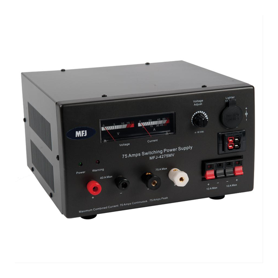
Thank you for purchasing the MFJ-4275MV Switching Power Supply.
The MFJ-4275MV is designed to deliver output current up to 75 Amps
intermittent or 70 Amps continuous at 13.8 Vdc.
Five types of output terminals are provided – 2 sets Anderson Powerpole
sets of 5-way binding posts, 2 sets of quick connect terminals and a cigarette
lighter socket. The variable output control adjusts output from 4 Vdc to 16 Vdc.
Output control has a pre-set detent position, which sets the output at 13.8Vdc.
The battery charger provides charging current up to 20 Amps peak and 5 Amps
continuous.
The total combined output current for this power supply is 75 Amps intermittent
or 70 Amps continuous at 13.8 Vdc. Each output connection has its output
current limit as shown by the following chart. Do not draw current over the
rated limited.
Output Connections
Gold 5-way binding posts
Black and Red binding Posts
Anderson Power Poles
Quick Connect Terminals
Cigarette Lighter Socket
Installation
Before plugging the MFJ-4275MV in an AC outlet make sure that the proper
input AC voltage is set to the correct AC voltage you are using. Select 115 for
100/110/120 AC operation or select 230 for 200/220/240 ac operation. 115V is
the default factory setting. Do not connect any device to the power supply yet.
Turn the power supply ON. Set the output voltage by adjusting the variable
output control in front of the power supply. The MFJ-4275MV has variable
output adjustment from 4 Vdc to 16 Vdc. The control will set the same output
voltage for all output connectors. The detent position on the output control sets
the output voltage at 13.8Vdc. Turn OFF the power supply after setting the
output voltage.
Connect the loads to the any of the output connectors. Positive to positive
terminal and negative to negative terminal. Reversed connection will damage
your equipment. For Anderson Powerpoles® connection, please refer to "the
assembly instruction" for detail assembly instructions. Connect the devices to
the power supply then turn ON the power supply.
Maximum combined output current is 75
Amps, Intermittent
75 Amps
40 Amps
35 Amps
10 Amps
10 Amps
®
, 2
Advertisement
Table of Contents

Related Manuals for MFJ MFJ-4275MV


Summary of Contents for MFJ MFJ-4275MV
- Page 1 10 Amps Installation Before plugging the MFJ-4275MV in an AC outlet make sure that the proper input AC voltage is set to the correct AC voltage you are using. Select 115 for 100/110/120 AC operation or select 230 for 200/220/240 ac operation. 115V is the default factory setting.
- Page 2 Protection The MFJ-4275MV has fault protection for output terminal short or overload (over 75 Amps), over voltage (pre-set at 16 Vdc) and component over heated. If any the above conditions occur, the warning LED will come on. Under fault condition, the power supply will automatically shut off. To reset, turn the unit OFF and wait 20 seconds, then turn the unit back on.
- Page 3 If you solder wires to the terminals, tin them lightly first. When soldering, flow solder only into the hole in which the wire is inserted. Be careful not to get any solder around the outer body of the terminal. F ig 3: Correct orientation of terminal and housing.
- Page 4 Wired and tested PC board products are covered by this warranty provided on the wired and tested PC board product is returned. Wired and tested PC boards installed in the owner’s cabinet or connected to switches, jacks, or cables, etc. sent to MFJ Enterprises, Inc. will be returned at the owner’s expense un-repaired.
Need help?
Do you have a question about the MFJ-4275MV and is the answer not in the manual?
Questions and answers