
Summary of Contents for Foxtech XLINK-30
- Page 1 XLINK-30 Long Range Video/Data Wireless Transmitting System User Manual V1.0 2020.09...
- Page 2 2. Please strictly abide by the local radio frequency management regulations. 3. Please follow the installation steps in the manual to use this product. Foxtech will not take legal responsibility for the damage of equipment or casualty caused by improper operation.
-
Page 3: Table Of Contents
XLINK-30 Long Range Video/Data Wireless Transmitting System User Manual Contents Package Includes Overview Air/Ground Unit Introduction Specification Interface Structure View and Installation Quick Start UI Configuration Pairing 2020 FOXTECH All Rights Reserved ©... -
Page 4: Package Includes
XLINK-30 Long Range Video/Data Wireless Transmitting System User Manual Package Includes 1x XLINK-30 Long Range Datalink/ 1x XLINK-30 Long Range Datalink/ Videolink Air Unit Videolink Ground Unit 2x Antenna Feeder 2x J30J Cable Set 2x Transmitter Antenna for Air Unit... -
Page 5: Overview
A great highlight of XLINK-30 is that it supports multi-node interlinked to form a communication mesh, in which one node is too far from the ground station to receive signals, it is able to transmit data to its nearest node, by which data can be sent back to the ground station. -
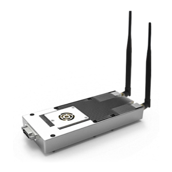
Page 6: Air/Ground Unit Introduction
Air/Ground Unit Introduction XLINK-30 needs to be used in pairs. The selection of antenna is determined by the scenarios that it is applied to. When used on aircraft, the sky end is referred to as the Air Unit, whereas the ground end is called the Ground Unit. -
Page 7: Specification
XLINK-30 Long Range Video/Data Wireless Transmitting System User Manual Specification Transmission Distance: 30km Frequency Band: 1410MHz ~ 1470MHz Transmitting Antenna: 2*Tx & 2*Rx Transmitting Power: ANT1, 0.5W ANT2, 0.5W Voltage: DC 9V ~ 36V; Typical Value 12V Power Consumption: Air Unit:≤12W Ground Unit:≤6W... -
Page 8: Interface
XLINK-30 Long Range Video/Data Wireless Transmitting System User Manual Interface 2020 FOXTECH All Rights Reserved ©... - Page 9 XLINK-30 Long Range Video/Data Wireless Transmitting System User Manual Warning Do not power on before installing ANT1/ANT2, otherwise it could cause damage to the device and burn it out. 2020 FOXTECH All Rights Reserved ©...
- Page 10 XLINK-30 Long Range Video/Data Wireless Transmitting System User Manual Pin Number Description Tx+(PHY) Tx from RJ45 Tx-(PHY) Reserved Reserved Pin Tx-TTL_1 Tx- from TTL 1 Reserved Reserved Pin Tx-TTL_2 Tx- from TTL 2 Reserved Reserved Pin RX(RS232) RX from RS232...
-
Page 11: Structure View And Installation
XLINK-30 Long Range Video/Data Wireless Transmitting System User Manual Structure View and Installation Before Install - 8x M2*14(GB/T818), cross head screwdriver - The depth of threaded hole should be reserved at least 3mm. - Torque requirement: 2±0.5Kg NOTES Do not cover the heat sink or the air inlet. -
Page 12: Quick Start
UI Configuration XLINK-30 has different data rates, which needs to be configured as needed. Step 1 Power on XLINK-30, and link it with PC by Ethernet. Then configure IP Address as shown below: IP Address 192.168.0.1 Subnet Mask 255.255.255.0 Step 2 Search 192.168.0.9 and enter on browser, next it will show a configuration interface as figure 6. - Page 13 XLINK-30 Long Range Video/Data Wireless Transmitting System User Manual SYSTEM PARAMETER NOTE WORK RF POINT Center Frequency Point Transmitting Channel 2T2R TXRX 1T2R 1T1R Bandwidth and Data Rate Selection SIGNAL BANDWIDTH AND DATA RATE A2G: Air Unit to Ground Unit...
-
Page 14: Pairing
XLINK-30 Long Range Video/Data Wireless Transmitting System User Manual Pairing Step 1 After one unit powers on, the SYNC LED indicator turns green. About 30s later, it starts to blink, which means it is pairing with the other unit. Step 2 If two units are powered on and paired, the indicator stops blinking and keeps on. -
Page 15: Faq
- Check the cable connection and wireless link is OK. - Check the IP address of computer is right. - Check the RTSP server address is correct. For more questions, please email to Foxtech after-sales service at after-sales@foxtechfpv.com. 2020 FOXTECH All Rights Reserved...
Need help?
Do you have a question about the XLINK-30 and is the answer not in the manual?
Questions and answers