
Summary of Contents for IAI ROBO Cylinder RCP6-RRA
- Page 1 RCP6-RRA RCP6-RRA ROBO Cylinder® Pulse Press ROBO Cylinder® Pulse Press www.intelligentactuator.com www.intelligentactuator.com...
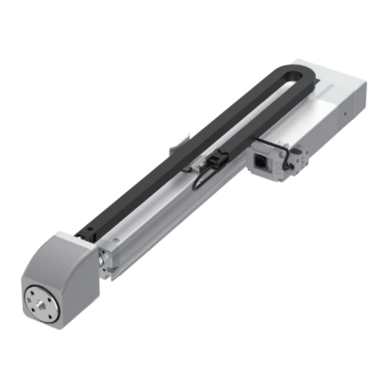
- Page 2 Actuator compatible with presses that allows for simple power control IAI's new pulse press Stepper motor What is a pulse press? A pulse press is an actuator combining a RCP6-RRA stepper motor and load cell, that is (pulse press) capable of performing power control.
- Page 3 Reasonable cost Reasonable cost Equipped with a stepper motor, it is less than half the cost of an IAI servo press. Equipped with a stepper motor, it is less than half the cost of an IAI servo press. Lineup Lineup Select from several types based on use (push force from 60N to 2,000N).
- Page 4 Easy setup using a dedicated tool Pushing/pulling can easily be setup using the PC teaching software or teaching pendant. PC teaching software (screenshot) Example of washer press fitting Position of 0mm Position of 50mm Push force of 302N reached Approach Push Complete...
-
Page 5: Specification Table
Model Specification Items Applicable Cable Series Type Encoder Motor type Lead Stroke controllers length Options RCP6 Side-mounted (RRA4R type) RRA4R PCON-CBP/CGBP rod 40mm width Lead 2.5mm Side-mounted (RRA6R type) RRA6R rod 58mm width Lead 1.5mm Side-mounted (RRA7R type) RRA7R rod 73mm width Lead 4mm (RRA7R type) Lead 2mm... - Page 6 RCP6 ROBO Cylinder® RCP6-RRA4R Battery- Body Width (Pulse press specification) less Stepper Side-mounted Absolute Motor Motor ■ Model Specification Items RCP6 RRA4R Series Type Encoder type Motor type Lead Stroke - Applicable controllers - Cable length Option Battery-less absolute Stepper motor 2.5mm 110mm PCON...
- Page 7 RCP6 ROBO Cylinder® ■ Main Specifications Item Description Item Description Lead Ball screw lead (mm) Drive system Ball screw, φ8mm, rolled C10 Maximum payload (kg) Positioning repeatability ±0.02mm (high-output enabled) Lost motion 0.1mm or less Payload Maximum payload (kg) Load cell rated capacity 600N (high-output disabled) Loading repeatability (Note 6) ±1.0% F.S.
- Page 8 RCP6 ROBO Cylinder® ■ Dimensions CAD drawings can be downloaded from our website. www.intelligentactuator.com The 2 counterbored mounting holes shown in the figure cannot be used. ST: Stroke (Note) When returning to the home position, the rod will move to the M.E. Be careful of interference with surrounding objects. M.E: Mechanical end S.E: Stroke end (43.3)
- Page 9 RCP6 ROBO Cylinder® RCP6-RRA4R...
- Page 10 RCP6 ROBO Cylinder® RCP6-RRA6R Battery- Body Width (Pulse press specification) less Stepper Side-mounted Absolute Motor Motor ■ Model Specification Items RCP6 RRA6R Series Type Encoder type Motor type Lead Stroke - Applicable controllers - Cable length Option Battery-less absolute Stepper motor 1.5mm 115mm PCON...
- Page 11 RCP6 ROBO Cylinder® ■ Main Specifications Item Description Item Description Lead Ball screw lead (mm) Drive system Ball screw, φ10mm, rolled C10 Maximum payload (kg) Positioning repeatability ±0.02mm (high-output enabled) Lost motion 0.1mm or less Payload Maximum payload (kg) Load cell rated capacity 600N (high-output disabled) Loading repeatability (Note 6) ±1.0% F.S.
- Page 12 RCP6 ROBO Cylinder® ■ Dimensions CAD drawings can be downloaded from our website. www.intelligentactuator.com ST: Stroke M.E: Mechanical end S.E: Stroke end (Note) When returning to the home position, the rod will move to the M.E. Be careful of interference with surrounding objects. (15.6) (43.3) Cable connection...
- Page 13 RCP6 ROBO Cylinder® RCP6-RRA6R...
- Page 14 RCP6 ROBO Cylinder® RCP6-RRA7R Battery- Body Width (Pulse press specification) less Stepper Side-mounted Absolute Motor Motor ■ Model Specification Items RCP6 RRA7R Series Type Encoder type Motor type Lead Stroke Applicable controllers Cable length Option Battery-less absolute Stepper motor 4 4mm 120mm PCON Refer to Options...
- Page 15 RCP6 ROBO Cylinder® ■ Main Specifications Item Description Item Description Lead Ball screw lead (mm) Drive system Ball screw, φ12mm, rolled C10 Maximum payload (kg) Positioning repeatability ±0.02mm (high-output enabled) Lost motion 0.1mm or less Payload Maximum payload (kg) Load cell rated capacity 2000N (high-output disabled) Loading repeatability (Note 6) ±1.0% F.S.
- Page 16 RCP6 ROBO Cylinder® ■ Dimensions CAD drawings can be downloaded from our website. www.intelligentactuator.com ST: Stroke M.E: Mechanical end S.E: Stroke end (Note) When returning to the home position, the rod will move to the M.E. Be careful of interference with surrounding objects. (15.6) (43.3) Cable connection...
- Page 17 RCP6 ROBO Cylinder® RCP6-RRA7R...
- Page 18 Options Options Brake Model Description When the actuator is mounted vertically, this works as a holding mechanism that prevents the rod from falling and damaging any attachments when the power or servo is turned off. Cable exit direction CJT / CJB / CJO Model Description This option allows the exit direction of the motor-encoder cable to be changed to top, bottom, or outside.
- Page 19 Options Foot bracket Model Description This bracket is used for mounting the actuator body from the top with bolts. The actuator body may be twisted or deformed if an insufficient number of mounting foot brackets are used. Actuator life could also be shortened. * Refer to the installation dimensions in the actuator drawing for the installation pitch between the foot brackets.
-
Page 20: Maintenance Parts
Maintenance Maintenance parts Maintenance part schematics ① Motor unit ⑥ ② Coupling spacer ⑤ ③ Timing belt ④ Load cell unit ③ ④ ⑤ Cable track assembly ⑥ Load cell cable assembly ② * Please refer to the dimensions on the product pages for the direction ①... -
Page 21: Mounting Orientation
Mounting orientation and load cell handling precautions Mounting orientation and load cell handling precautions Mounting orientation Horizontal mounting on flat surface Vertical mounting Horizontal mounting to side Horizontal mounting suspended Keep the body installation surface and workpiece mounting surface flatness at 0.05mm/m or lower. Uneven flatness will increase the sliding resistance of the slider and may cause a malfunction. - Page 22 PCON-CBP Controller Pulse press dedicated controller (*1) (*1) CC-Link IE Field and MECHATROLINK-I/II connection specifications are not CE Marking compliant Features High resolution battery-less absolute encoder support Pulse press specification actuators are equipped with high resolution battery-less absolute encoders. As no battery is needed for retaining position data, it is possible to save space around the control panel, which helps to keep down the cost of the equipment.
-
Page 23: List Of Models
PCON-CBP Controller List of Models Model PCON-CBP/CGBP External view Field network type Positioner I/O type type DeviceNet CC-Link CC-Link IE Field PROFIBUS-DP CompoNet MECHATROLINK EtherCAT EtherNet/IP PROFINET IO connection connection connection connection connection I,II connection connection connection connection speci cation speci cation speci cation speci cation... -
Page 24: System Configuration
<Model: IA-OS-C> Included with the controller for PIO speci cation PIO cable (See P. 30) <Model: CB-PAC-PIO020> * Please contact Standard 2m IAI for the current supported versions. Option 24VDC power supply (See P. 29) Dedicated connection cable <Model: PSA-24> Controller <Model: PCON-CBP/CGBP>... - Page 25 PCON-CBP Controller PIO Input/Output Interface Input/output Input/output External input speci cation External input speci cation Item Specifications Item Specifications Input voltage 24VDC ±10% Load voltage 24VDC Input current 5mA, 1 circuit Maximum load current 50mA, 1 circuit ON voltage: 18VDC min. ON/OFF voltage Leakage current 2mA max./point...
- Page 26 PCON-CBP Controller PIO Patterns and Signal Assignments The table below lists the signal assignments for the I/O flat cable under different PIO patterns. Connect an external device (such as a PLC) according to this table. Parameter No.25, "PIO Pattern Selection" Category PIO function Positioning mode Teaching mode 256-point mode 512-point mode Solenoid valve mode 1 Solenoid valve mode 2 Force control mode 1 Force control mode 2...
-
Page 27: Mode Description
PCON-CBP Controller Field Network Specification: Explanation of Operation Modes If controlling via a field network, one of the following 8 modes can be selected to operate the actuator. Please note that the data areas required on the PLC side will vary depending on the mode. ... -
Page 28: Specification List
PCON-CBP Controller Specification List Speci cation Item PCON-CBP/CGBP Number of controlled axes 1 axis Power supply voltage 24VDC ±10% Load current High-output setting disabled: 2.2A max. (including control-side current consumption) High-output setting enabled: 3.5A rated / 4.2A max. (Note 1) Electromagnetic brake power (for actuator with brake) 24VDC±10%, 0.15A (max.) Inrush current... -
Page 29: External Dimensions
PCON-CBP Controller External Dimensions CAD drawings can be downloaded from our website. www.intelligentactuator.com <PCON-CBP/CGBP> Screw mounting specification DIN rail mounting specification 93.3 84.8 78.1 69.6 Part Names Controller display status LED Axis number setting switch Indicates the status of the controller. Used to set an address to identify each controller, when controllers are linked. - Page 30 (software only, for customers who already own a dedicated connection cable) Model * Please purchase through your distributor and a download link will be sent to your valid email address. Configuration Please contact IAI for the current supported versions. (Your dedicated connection cable) PC software (Download Only)
- Page 31 PCON-CBP Controller Maintenance Parts When placing an order for a replacement cable after purchasing a product, please use the model name shown below. Table of compatible cables Model name Motor/encoder cable Motor/encoder robot cable RCP6-RRAR-LCT CB-CAN-MPA CB-CAN-MPA-RB Model name PIO flat cable PCON-CBP/CGBP CB-PAC-PIO...
- Page 32 Hongqiao Rd., Shanghai 200030, China Hongqiao Rd., Shanghai 200030, China IAI Robot (Thailand) Co., Ltd. IAI Robot (Thailand) Co., Ltd. JAPAN Headquarters : 577-1 Obane, Shimizu-ku, Shizuoka-shi, Shizuoka, 424-0103, JAPAN JAPAN Headquarters : 577-1 Obane, Shimizu-ku, Shizuoka-shi, Shizuoka, 424-0103, JAPAN 825 Phairojkijja Tower 7th Floor, Debaratana Rd.,...
Need help?
Do you have a question about the ROBO Cylinder RCP6-RRA and is the answer not in the manual?
Questions and answers