Table of Contents
Advertisement
Quick Links
Advertisement
Chapters
Table of Contents
Troubleshooting

Subscribe to Our Youtube Channel
Summary of Contents for Union Instruments Pury250 S
- Page 1 Operating Instructions Gas Cooler Pury250 S...
- Page 2 April-2016 V1.00 Union Instruments GmbH Zeppelinstrasse 42 76185 Karlsruhe Germany +49 (0)721-680381-0 +49 (0)721-680381-33 support@union-instruments.com http://www.union-instruments.com Article number: 03608199998 © 2016 This documentation is protected by copyright. All rights, in particular the rights of translation, reprint, extraction of figures, radio transmission, and duplication by photomechanical or other means and of storage in data processing systems, in whole or in part, are reserved.
-
Page 3: Table Of Contents
Table of contents Technical data ......................5 Dimensions ........................5 Device parameters ....................... 6 Data and specifications....................7 EC Declaration of Conformity..................9 Safety information ...................... 11 Warning information and symbols................. 11 Principle, intended use ....................12 Personnel and qualification................... 12 Safety information...................... - Page 4 9.3.3 Switching temperature of fan ..................41 9.3.4 Difference between ambient and cooler temperatures ..........42 9.3.5 Pump condensate quantity ..................42 Menu for service settings ..................... 43 9.4.1 Password for service mode ..................43 9.4.2 Temperature sensor cooler ..................43 9.4.3 Temperature sensor outside temperature ..............
-
Page 5: Technical Data
1 Technical data 1.1 Dimensions Weight approx. 12.6 kg (28lbs) -
Page 6: Device Parameters
Technical data 1.2 Device parameters See device name plate and data and information accompanying the device. Example name plate: Fig. 1.1: Name plate (example) 1. Device description 2. Technical information... -
Page 7: Data And Specifications
Technical data 1.3 Data and specifications Gas inputs Input process gas: Output process gas: Output condensate: Gas connections: Compression fitting 6mm / ¼” Max. gas input pressure: 750 mbar absolute (11 psi) Min. gas input pressure: -100 mbar relative Gas pressure drop: 5 - 10 mbar (2 - 4”... - Page 8 Technical data NOTICE When the PURY250S is used in outside environmental conditions, additional anti- freeze measures must be discussed with Union Instruments GmbH!
-
Page 9: Ec Declaration Of Conformity
EC Declaration of Conformity 2 EC Declaration of Conformity Der Hersteller/The manufacturer Union Instruments GmbH Zeppelinstrasse 42 76185 Karlsruhe erklärt hiermit, dass folgend bezeichnete Produkte / hereby declares, that following named products: Produktbezeichnung: Gaskühler Gerätegruppe: PURY250 Product name Gas Cooler device group: PURY250 konform sind mit den Anforderungen, die in der EU –... - Page 10 EC Declaration of Conformity...
-
Page 11: Safety Information
3 Safety information 3.1 Warning information and symbols The operating instructions use the following nomenclature and symbols for especially important information: DANGER For an immediate danger that can lead to serious physical injury or death! WARNING For a potentially dangerous situation that can lead to serious physical injury or death! NOTICE For a potentially dangerous situation that can lead to minor physical injury! This... -
Page 12: Principle, Intended Use
Additional equipment or accessory parts not installed, supplied, or made by UNION Instruments GmbH require manufacturer's approval by UNION Instruments GmbH! Any warranty is otherwise voided! 3.3 Personnel and qualification Gas connections and work on the electrical equipment of the gas cooler should only be carried out by a skilled person in compliance with safety provisions. -
Page 13: Safety Information
Safety information 3.4 Safety information 3.4.1 General safety information WARNING Only operate the gas cooler when all protective equipment is present and operational! Further safety information: Before the corresponding chapters! 3.4.2 Information on specific hazards WARNING • After installation, all gas-conveying parts must be checked for leak tightness according to national regulations. -
Page 14: Performing A Workplace Hazard Analysis
If you desire additional information or if specific problems arise that are not covered in detail in this manual, you will receive information by contacting the following address or local representative: Union Instruments GmbH Zeppelinstrasse 42 76185 Karlsruhe... -
Page 15: Protective Equipment
4 Protective equipment 4.1 Enclosure cover Fig. 4.1: Enclosure cover... -
Page 16: Markings And Warning Information
Protective equipment 4.2 Markings and warning information Fig. 4.2: Markings and warning information Name plate Fig. 4.3: Warning in the enclosure 115/230 V voltage... -
Page 17: Connections
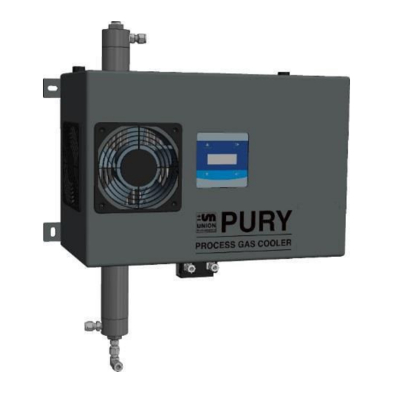
5 Connections Fig. 5.1: Product description 1. Enclosure screws, 4 pieces 8. Inlet process gas 2. Side fans, left, right 9. Display with operator input keys 3. Cooler tube with filter 10. Front fan 4. Condensate pump inlet side, suction 11. -
Page 18: General Description
Risk of injury/damage! The use of non-approved accessories may cause damage and endanger persons. Any warranty is voided in this case. The owner is then liable for damage that occurs! Only use genuine accessories or accessories approved by Union Instruments GmbH. -
Page 19: Transport, Installation, And Acceptance
6 Transport, installation, and commissioning NOTE The gas cooler is generally commissioned by Union Instruments GmbH or service technicians. When it is not transported, installed, and commissioned by Union Instruments GmbH (e.g., internal transport/resale), the suitable procedure must be agreed with Union Instruments GmbH ( Chapter 12 Service). -
Page 20: Environmental Conditions
6.2 Environmental conditions NOTICE Comply with environmental conditions for storage and installation! Comply with environmental conditions! Contact Union Instruments GmbH if the gas cooler is stored for longer than 3 months or must be operated or stored outside the prescribed environmental conditions! 6.2.1 Storage conditions... -
Page 21: Wall Mounting
Transport, installation, and acceptance 6.4.1 Wall mounting The gas cooler is intended to be wall mounted using the attached wall brackets. The wall used for mounting must be sufficiently sturdy to bear the weight of the gas cooler. Secure the gas cooler to a fixed wall using the 4 mounting points. Fig. -
Page 22: Fig.6.2: Minimum Installation Space
Transport, installation, and acceptance Provide adequate room for maintenance purposes. Filter element is removed upwards for maintenance, housing cover is removed downwards. Fig. 6.2: Minimum installation space... -
Page 23: Process Gas
Transport, installation, and acceptance 6.4.2 Process gas NOTE • Connection parts must be clean and free of any contamination. • The input pressure for the gas connections must not exceed the specifications of the information sticker on the gas cooler. •... -
Page 24: Fig.6.3: Connection Of Input/Output Process Gas
Transport, installation, and acceptance Fig. 6.3: Connection of input/output process gas Item No. Designation Input Process Gas, max. 0,75 bar (11 psig) I1.1 Output Process Gas to analyzer O1.2 If required, the male coupling "O1.2" and the closure plug "Option O1.2" can be swapped. -
Page 25: Condensate Line
Transport, installation, and acceptance 6.4.3 Condensate line NOTE • Route hose to avoid kinks, blockages and in a downward sloping manner. • Install output condensate in a frost-proof manner! • Discharge condensate without any back pressure! • A ventilated container is recommended – inspect/clean regularly. Installation of condensate line Compression fittings 6mm or ¼”... -
Page 26: Fig.6.5: Output Condensate
Transport, installation, and acceptance Make the connections between gas cooler and pump. Insert hose into screw fitting on the output condensate and install compression fitting according to instructions. Fig. 6.5: Output condensate Connect condensate hose onto suction side of the pump and install compression fitting according to vendors instructions. -
Page 27: Fig.6.7: Condensate Hose After Installation
Transport, installation, and acceptance Fig. 6.7: Condensate hose after installation Connect hose for the condensate discharge to the pressure side of the pump. Use compression fittings according to vendors instructions. -
Page 28: Electrical Connection
Transport, installation, and acceptance 6.4.4 Electrical connection DANGER Danger of electric shock! Connections to the electrical equipment of the gas cooler must only be carried out by skilled electricians in accordance with NEC and applicable local rules. Parts of the open gas cooler marked with the adjacent symbol may still carry voltage even when the main switch is switched off! If required, disconnect the gas cooler from the line power supply! 6.4.5 Electrical interfaces... -
Page 29: Fig.6.8: Line Power Supply
Transport, installation, and acceptance Connection of line power supply Fig. 6.8: Line power supply Connect the gas cooler to the line power supply using connections L1, N, PE in accordance with all national and applicable local requirements. Ground fault circuit interrupter and back-up fuse (16 A) required for L and N connections. Remove enclosure cover, 4 screws on top and bottom of cover. -
Page 30: Fig.6.10: Relays: K1-K2
Transport, installation, and acceptance Electrical interfaces Relays Fig. 6.10: Relays: K1 – K2 Designation Function Relay K1 Signal that dew point has been reached. The CWD2005 calorimeter will not start until the dew point temperature is reached. Use as a control signal also possible. -
Page 31: Safety Precautions Of The User
Endangerment of people and equipment when the gas cooler is commissioned by non-instructed personnel! Allow only instructed/trained service technicians to carry out commissioning! 6.6 Documentation NOTE Union Instruments GmbH recommends keeping a maintenance manual and documenting all maintenance work and tests. Union Instruments GmbH recommends documenting the proper installation and commissioning. - Page 32 Transport, installation, and acceptance...
-
Page 33: Commissioning/Switching On
7 Commissioning/Switching on NOTICE In order to establish start readiness, also establish the start status of linked system components according to their specific operating instructions! NOTE The following table contains full list of steps for commissioning after an extended downtime. To switch on the gas cooler again after a short shutdown, some steps can be omitted: Right column! - Page 34 Commissioning/Switching on...
-
Page 35: Description Of The Hmi/Operator Control Elements
8 Description of the HMI and operator control elements NOTE This chapter contains only elements for operation of the gas cooler by the normal operator. 8.1 Workstation/HMI Fig. 8.1: Workstation/HMI Item Designation Function/Activity Display Display status. - Page 36 Description of the HMI and operator control elements...
-
Page 37: Operation
9 Operation WARNING Risk of injury! Only operate the gas cooler when all lines are installed and have been checked for leak tightness in accordance with country-specific regulations. -
Page 38: Description Of Display
Operation 9.1 Description of display 9.1.1 Operation of membrane keyboard The software controller is operated using a membrane keyboard. The buttons shown can be selected by a keypress, the menu structures are deliberately kept flat so that functions can be accessed quickly. NOTICE Damage to membrane keyboard! Operation with objects other than fingers may damage the membrane keyboard! -
Page 39: Display Area
Operation 9.1.2 Display area Cool 3.0° C Amb 25.0 ° C Fig. 9.2: Display Item Designation Function Display Display of status information, measured values, here cooler temperature 3°C ambient temperature 25° C 9.2 Available displays NOTE The available displays and their function are described below. The displays are accessed using the menu and function keys shown in the chapter headings. -
Page 40: Menu Structure
Operation 9.2.1 Menu structure NOTE Some of the red-framed menu items may affect the function after a change. Main menu: Setpoint Target cooler value Setpoint EXT Threshold value for external cooler Diff Ambient Minimum difference for external cooler Pump Amount Condensate flow rate of pump Main menu: Back/ESC Hold key 5 seconds Password Service Mode NTC0Offs... -
Page 41: Navigation With Keys Up ▲, Down ▼, Esc, And Enter
Operation 9.2.2 Navigation with keys Up ▲, Down ▼, ESC, and Enter Values are changed with the • ▼▲ keys Navigation between the • displays/menus with the "Next" and "ESC" keys. 9.3 Menu for closed-loop control 9.3.1 Main menu Display of cooler temperature and ambient temperature. key takes you to the next menu 9.3.2 Target cooling temperature Display and setting of the target temperature of the cooler. -
Page 42: Difference Between Ambient And Cooler Temperatures
Operation 9.3.4 Difference between ambient and cooler temperatures Difference is a measure for the degree of drying. Default value is 10° C, setting range is "Off", 10° C to 30° C. "Off" means that no temperature difference is permitted. Cooling to the dew point temperature will be carried out. -
Page 43: Menu For Service Settings
Operation 9.4 Menu for service settings NOTE Disturbance of function! When the following parameters are changed, the function of the device may be affected. Allow only authorized persons to make changes! From the main menu – Display of cooler temperature/ambient temperature - hold down the ESC key for 5 seconds. -
Page 44: Temperature Sensor Outside Temperature
Operation 9.4.3 Temperature sensor - outside temperature Display and setting of the offset of the temperature sensor. Corrects the temperature by the corresponding value. Default value is +99, setting range is - 99 to +99. 9.4.4 Operation Window Display and setting of the operating range Default value is 2° C, setting range: 2°... -
Page 45: Decommissioning / Switching Off
Maintenance 10 Decommissioning / Switching off NOTICE In order to decommission the gas cooler, also decommission any linked system components according to their specific operating instructions! NOTE The following table contains steps for decommissioning for an extended downtime. To switch off the gas cooler only temporarily, some steps can be omitted: Switching off column! WARNING Risk of serious injury from escaping gases! - Page 46 Maintenance Decommissioning / Switching off Decommissi Switching Steps oning Disconnect the device from the process, professionally plug the line. Purge gas cooler with ambient air. Bring linked system components to a halt. Clean cooler, see maintenance instructions Switch off voltage supply If the gas cooler is to be taken out of service only temporarily, the process ends here! Professionally disconnect/switch off owner-side energy supplies, media supply, and signal transmission.
-
Page 47: Maintenance
Maintenance 11 Maintenance The function of the gas cooler can only be guaranteed when the maintenance intervals are adhered to. 11.1 Preparations Supply lines of linked system components can be closed for maintenance purposes. These must be reopened after the device is put back into service. DANGER Risk of serious injury from electrical shock! •... -
Page 48: Maintenance Work/Inspection
Maintenance 11.2 Maintenance work/Inspection NOTE Maintenance work must be performed according to the inspection and maintenance schedule! The nature and amount of wear depends greatly on the individual use and operating conditions. All specified intervals are therefore guide values. Interval Check (recommended) Weekly check... - Page 49 Maintenance...
-
Page 50: Replacing Filter Inserts
Maintenance 11.2.1 Replacing filter inserts Disassembly To replace the filter inserts, the cooler tube must be removed. 1. Unscrew compression fittings of the input process gas and output process gas. 2. Unscrew compression fitting of condensate hose on cooler tube. 3. -
Page 51: Fig.11.2: Replacing The Filter Insert
Maintenance Replacing the wire filter inserts 1. Screw off wire filter inserts downwards from the tube. Observe the correct order, two different types are used. Filter inserts can also be pulled out downwards with a suitable tool. 2. Insert new filters in the correct order, ensure a secure fit! Fig. - Page 52 Maintenance Assembly 1. Clean or replace the O-rings for the upper and lower parts. 2. Insert wire filter inserts in tube. 3. Assembly in reverse order. Fig. 11.3: O-rings of upper/lower parts...
-
Page 55: Troubleshooting
12 Troubleshooting NOTE The function of the UNION calorimeter connected to the gas cooler may be disturbed by the reaching of a readiness condition. Problems in the gas cooler may negatively affect the cleaning and cooling functions and subsequent analyses. 12.1 Preparations Supply lines of any linked system components can be closed for maintenance purposes. -
Page 56: Changing/Replacing Fuses
Troubleshooting 12.2 Changing/replacing fuses Only skilled electricians or service technicians are permitted to replace fuses. Only replace with fuse types specified by UNION. 12.3 Troubleshooting Description Cooler/fan does not start up. • A check must be made to determine whether the device is properly connected to the power supply system. -
Page 57: Service
13 Service NOTE Union Instruments GmbH is available to answer any questions. In case of orders or technical questions, please provide your customer number, phone number where you can be reached, the gas cooler type and number (see name plate), and required spare parts/bills of material numbers, if applicable. - Page 58 Service...
-
Page 59: Related Documents
14 Related documents • Declaration of Conformity • Service documentation, optional... - Page 60 Related documents...
-
Page 61: Disposal
15 Disposal Following decommissioning, take back the device to Union Instruments GmbH if possible. Suggestion: Have Union Instruments GmbH dispose of your gas cooler. WARNING Risk of injury from electricity and, if applicable, gases in the process gas analyzer! Before removal, disconnect gas cooler from line power supply! - Page 62 Disposal...
-
Page 63: Spare Parts
In the event that components are discontinued or components of other manufacturers are used, this requires manufacturer's approval by UNION Instruments GmbH! Spare parts can be ordered from Union Instruments GmbH: Chapter 12 Service. Make a note of the gas cooler type and serial number ( Name plate). - Page 64 Spare parts...
-
Page 65: Appendix
Operation ........... 37 Contact Operation of membrane keyboard ..38 Service..........57 Operator control elements ....35 UNION Instruments Gmb ....14 Operator input with keys ....41 Decommissioning ......45, 61 Personnel and qualification ....12 Display ..........39 Process gas ......... 23 Displays .......... -
Page 66: List Of Figures
Appendix List of figures Fig.1.1: Name Plate (example) ..................6 Fig.4.1: Enclosure Cover ....................15 Fig.4.2: Markings and Warning information..............16 Fig.4.3: Warning in the enclosure................... 16 Fig.5.1: Product description ................... 17 Fig.6.1: Wall Mounting ....................21 Fig.6.2: Minimum Installation space................22 Fig.6.3: Connection of input/output process gas ............
Need help?
Do you have a question about the Pury250 S and is the answer not in the manual?
Questions and answers