Table of Contents
Advertisement
Quick Links
RC-1170/1270
Redundancy Switch Controllers
Installation and Operation Manual
Part Number MN-RC-1170/1270
Revision 0
IMPORTANT NOTE: The information contained in this document supersedes all previously published
information regarding this product. Product specifications are subject to change without prior notice.
Advertisement
Table of Contents

Summary of Contents for Comtech EF Data RC-1170
- Page 1 RC-1170/1270 Redundancy Switch Controllers Installation and Operation Manual Part Number MN-RC-1170/1270 Revision 0 IMPORTANT NOTE: The information contained in this document supersedes all previously published information regarding this product. Product specifications are subject to change without prior notice.
- Page 2 RC-1170/1270 Redundancy Switch Controllers Revision 0 Copyright © 2021 Comtech EF Data. All rights reserved. Printed in the USA. Comtech EF Data, 2114 West 7th Street, Tempe, Arizona 85281 USA, 480.333.2200, FAX: 480.333.2161 Revision History Date Description Sept 2021 Initial Release.
-
Page 3: Table Of Contents
Rack-Mount Installation ......................2–2 Connectors ..........................2–3 Power Connection........................2–3 2.3.1.1 DC Filter Input Module (RC-1170 Only) ................ 2–4 J1, Control and Bias........................2–5 J3, EIA 232/485 ......................... 2–7 J4, ‘10/100 ETHERNET’ Management Utility Port..............2–8 Bias Select Switch ........................2–9 Current Cal Switch ........................ - Page 4 RC-1170/1270 Redundancy Switch Controllers Revision 0 CHAPTER 3. FRONT PANEL OPERATION ..................3–1 Overview ............................3–1 LEDs ............................3–2 Keypad ............................3–3 Vacuum Fluorescent Display (VFD) ..................3–3 3.1.3.1 Screen Saver ......................... 3–3 Front Panel Menus ........................3–4 Select: Menu ..........................3–4 3.2.1.1...
- Page 5 5.2.1.1 CEFD Root MIB File ...................... 5–2 5.2.1.2 RC-1170/1270 Redundancy Switch Controller MIB File ..........5–2 5.2.1.3 RC-1170/1270 Redundancy Switch Controller Traps MIB File ........5–2 5.2.2 SNMP Community Strings ......................5–3 5.2.3 SNMP Traps ..........................5–3 Telnet Interface ..........................5–8 5.3.1...
- Page 6 Figure 5-6. RC-1170/1270 Redundancy Switch Controller HTTP Interface ‘Splash’ Page Example ..5–12 Figure 5-7. RC-1170/1270 Redundancy Switch Controller HTTP Interface Menu Tree ......5–13 Figure 5-8. RC-1170/1270 Redundancy Switch Controller ‘Home | Home’ Page (50 W Unit Example Shown) ............................5–15 Figure 5-9.
- Page 7 RC-1170/1270 Redundancy Switch Controllers Revision 0 Figure A-11. C-Band LNB 1:2 Redundant System Assembly ..............A-11 Figure A-12. C-Band LNB 1:2 Redundant System (Exploded View) ............A-12 Figure A-13. Ku-Band LNA 1:2 Redundant System Assembly ............... A-13 Figure A-14. Ku-Band LNA 1:2 Redundant System (Exploded View) ............. A-14 Figure A-15.
- Page 8 RC-1170/1270 Redundancy Switch Controllers Revision 0 Acronym List Acronym Description / Definition First Use Page CEFD Comtech EF Data Circuit Identification 5-23 Electronic Industries Association Preface-ii Electromagnetic Compatibility Preface-v Electrostatic Discharge Federal Communications Commission Preface-v Internet Protocol IP Address Liquid Crystal Diode...
- Page 9 RC-1170/1270 Redundancy Switch Controllers Revision 0 Units of Measurement Unit / Symbol Definition Ω Ampere Alternating Current bits per second ˚C Celsius (degrees) Direct Current Hertz kiloHertz decibel Decibels relative t the carrier Decibel-milliwatts ˚F Fahrenheit (degrees) Kbps Kilobit per second...
- Page 10 RC-1170/1270 Redundancy Switch Controllers Revision 0 BLANK PAGE Table of Contents TOC-8 MN-RC-1170/1270...
-
Page 11: Preface
This manual provides installation and operation information for Comtech EF Data (CEFD) RC- 1170/1270 Redundancy Switch Controllers. Conventions and References Patents and Trademarks See all of Comtech EF Data's Patents and Patents Pending at http://patents.comtechefdata.com. Comtech EF Data acknowledges that all trademarks are the property of the trademark owners. Preface MN-RC-1170/1270... -
Page 12: Warnings, Cautions, Notes, And References
A NOTE: gives you important information about a task or the equipment. A REFERENCE directs you to important operational information or details furnished elsewhere, either in the manual or in adjunct Comtech EF Data publications. Examples of Multi-Hazard Notices... -
Page 13: Recommended Standard Designations
RC-1170/1270 Redundancy Switch Controllers Revision 0 Recommended Standard Designations Electronic Industries Association (EIA) designations supersede Recommended Standard (RS) designations. Reference to the old RS designations may appear where it might concern actual text (e.g., RS-232) displayed on the product rear panels and on screens or pages in the Serial Remote or HTTP (Web Server) Interfaces. -
Page 14: Restricted Access Location
RC-1170/1270 Redundancy Switch Controllers Revision 0 Restricted Access Location In Nordic Countries, equipotential bonding should be applied, using the permanently connected ground stud, by a qualified service person. Electrical Installation CAUTION Connect the unit to a power system that has separate ground, line and neutral conductors. -
Page 15: European Union Radio Equipment And Telecommunications Terminal Equipment (R&Tte) Directive (1999/5/Ec) And En 301 489-1
RC-1170/1270 Redundancy Switch Controllers Revision 0 European Union Radio Equipment and Telecommunications Terminal Equipment (R&TTE) Directive (1999/5/EC) and EN 301 489-1 Independent testing verifies that the unit complies with the European Union R&TTE Directive, its reference to EN 301 489-1 (Electromagnetic compatibility and Radio spectrum Matters [ERM];... -
Page 16: European Union Low Voltage Directive (Lvd) (2014/35/Ec)
In accordance with the European Union Radio Equipment Directive 2014/53/EC, the unit should not be directly connected to the Public Telecommunications Network. CE Mark Comtech EF Data declares that the unit meets the necessary requirements for the CE Mark. Preface MN-RC-1170/1270... -
Page 17: Product Support
Comtech EF Data Corporation, would affect the reliability or detracts from the performance of any part of the product, or is damaged as the result of use in a way or with equipment that had not been previously approved by Comtech EF Data Corporation. -
Page 18: Exclusive Remedies
The buyer shall pass on to any purchaser, lessee, or other user of Comtech EF Data Corporation’s products, the aforementioned warranty, and shall indemnify and hold harmless Comtech EF Data... -
Page 19: Chapter 1. Introduction
RC-1170/1270 Redundancy Switch Controllers Revision 0 Chapter 1. INTRODUCTION This chapter provides an overview and specifications for the Comtech EF Data (CEFD) redundancy switch controllers: • RC-1170 (1:1) • RC-1270 (1:2) Future Product Figure 1-1. RC-1170 (1:1) Figure 1-2. RC-1270 (1:2) Introduction 1–1... -
Page 20: Overview
Printed Circuit Boards (PCBs). A complete redundant system consists of: • RC-1170 (future product) or RC-1270 Redundancy Switch Controllers • Redundant amplifier plate with two or three Low Noise Amplifier (LNA)/Low Noise Block- down Converter (LNB)s •... -
Page 21: Figure 1-3. Indoor Controller/Outdoor 1:2 Lna Switch System
RC-1170/1270 Redundancy Switch Controllers Revision 0 Figure 1-3. Indoor Controller/Outdoor 1:2 LNA Switch System Figure 1-4. Indoor Controller/Outdoor 1:1 LNA Switch System Introduction 1–3 MN-RC-1170/1270... -
Page 22: Figure 1-5. Indoor Controller/Outdoor 1:2 Lnb Switch System
RC-1170/1270 Redundancy Switch Controllers Revision 0 Figure 1-5. Indoor Controller/Outdoor 1:2 LNB Switch System Figure 1-6. Indoor Controller/Outdoor 1:1 LNB Switch System Introduction 1–4 MN-RC-1170/1270... -
Page 23: Specifications
RC-1170/1270 Redundancy Switch Controllers Revision 0 Specifications Item Description Power Input 90 to 240 VAC, 47 to 63 Hz, less than 40 W Input Nominal current 0.65 A (standard) Power Output 13/18 VDC, 0.5 A per LNA/LNB (standard) 14 VDC, 600 mA per LNA/LNB (optional), 150 mA total minimum load, each outlet protected by a current- limiting regulator. -
Page 24: 1.2.3 Indicators
RC-1170/1270 Redundancy Switch Controllers Revision 0 1.2.3 Indicators Note: Applies to RC-1170 only (1:2 systems). Item Parameters Description GREEN: Un-muted and no-fault present • Unit 1, 2, & 3 YELLOW: Muted • Tri-color LED Status RED: Fault Detected • Note: A flashing LED indicates unit is bypassed by the switch system. -
Page 25: Chapter 2. Installation And Connectors
CEFD to submit a damage report. 4. Read the online manual. The RC-1170 (future)/1270 Redundancy Switch Controller and its power cord are packaged and shipped in a reusable cardboard carton containing protective foam spacing (Figure 2-1). The Installation and Operation Manual can be found on the CEFD website, www.comtechefdata.com... -
Page 26: Rack-Mount Installation
RC-1170/1270 Redundancy Switch Controllers Revision 0 Item Description Reusable cardboard carton and protective foam spacing Packing Slip Power Cord Redundancy Switch Controller Figure 2-1. Redundancy Switch Controller Package Content Rack-Mount Installation The unit is designed to mount in a standard 19” (48.26 cm) rack cabinet or enclosure. A rack- mount installation requires 1.75”... -
Page 27: Connectors
RC-1170/1270 Redundancy Switch Controllers Revision 0 Connectors Figure 2-2. RC-1170/1270 Rear Panel Connectors Power Connection The detachable power cords are intended to mate with the AC receptacle/filter at the rear of the unit. The power cords are designed to be connected to two independent power sources, each providing an AC voltage between 90 and 240 V. -
Page 28: Dc Filter Input Module (Rc-1170 Only)
RC-1170/1270 Redundancy Switch Controllers Revision 0 2.3.1.1 DC Filter Input Module (RC-1170 Only) Note the following: • The DC Filter Input Module input voltage is -48 VDC nominal, -36 VDC minimum, -72 VDC maximum. • Power Module Manufacturer: TE Connectivity P/N 6DAF1 (CEFD P/N 506-0015-002). -
Page 29: J1, Control And Bias
RC-1170/1270 Redundancy Switch Controllers Revision 0 J1, Control and Bias The LNA/LNB J1 connector is a 25-pin D socket and can mate with any 25-pin miniature D connector plug. See Table 2-2 for connector pinouts. Table 2-2. ‘J1’ Controller LNA/LNB Output Connector... - Page 30 RC-1170/1270 Redundancy Switch Controllers Revision 0 Figure 2-5 and Figure 2-6 shows the waveguide switch and indicator wiring. Figure 2-4. Waveguide Switch Wiring 1:1 Configuration Figure 2-5. Waveguide Switch Wiring 1:2 Configuration, RC-1270 Only Installation and Connectors 2–6 MN-RC-1170/1270...
-
Page 31: J3, Eia 232/485
RC-1170/1270 Redundancy Switch Controllers Revision 0 J3, EIA 232/485 Table 2-3. ‘J3’ 2-Wire EIA-485 Interface Connector Pinout Pin # Description Function +RX/TX Signal -RX/TX Signal Complement +RX/TX Signal -RX/TX Signal Complement Ground Table 2-4. ‘J3’ 4-Wire EIA-485 Interface Connector Pinout... -
Page 32: J4, '10/100 Ethernet' Management Utility Port
RC-1170/1270 Redundancy Switch Controllers Revision 0 Pin # Description Function Transmit Data J4, ‘10/100 ETHERNET’ Management Utility Port The ‘J4 Unit Comm’ 100BaseTX Ethernet RJ-45 port is used to operate the Ethernet remote control interfaces. It is also used for updating the modem firmware. This receptacle uses a CAT5 Ethernet cable for connection to an Ethernet hub, router, switch, Personal Computer (PC), etc. -
Page 33: Bias Select Switch
RC-1170/1270 Redundancy Switch Controllers Revision 0 Table 2-7. Controller to Unit Ethernet Connection (optional) Pin # Description Ethernet Ethernet Ethernet Aux Mute driven to the remote Unit +24 V from the remote Unit Ethernet Summary Fault from remote unit Remote GND Note: The Controller/Unit interconnection uses some of the typically unused 10/100 Base-T conductors for fault status, AUX Mute, 24 V parasitic power, and controller to unit GND. - Page 34 RC-1170/1270 Redundancy Switch Controllers Revision 0 BLANK PAGE Installation and Connectors 2–10 MN-RC-1170/1270...
-
Page 35: Chapter 3. Front Panel Operation
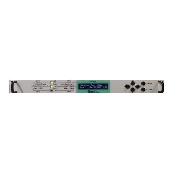
The unit will not be damaged if the waveguide switch indicator connections are not made. However, the online indicators will be erroneous. Overview Future Product Figure 3-1. RC-1170 Front Panel Figure 3-2. RC-1270 Front Panel Front Panel Operation 3–1 MN-RC-1170/1270... -
Page 36: Leds
RC-1170/1270 Redundancy Switch Controllers Revision 0 Table 3-1. Front Panel Features Feature Description Function LED Indicators The LEDs indicate, in a summary fashion, the status of the modem. The keypad comprises six individual keyswitches. The keys have a positive ‘click’... -
Page 37: Keypad
RC-1170/1270 Redundancy Switch Controllers Revision 0 Keypad The keypad has an auto-repeat feature. When you hold down a key for more than one second, the key action repeats, automatically, at the rate of 15 keystrokes per second. This is particularly useful when editing numeric field with many digits, such as frequency or data rate. -
Page 38: Front Panel Menus
RC-1170/1270 Redundancy Switch Controllers Revision 0 Front Panel Menus Opening Screen The opening screen displays the software version and the unit serial number. • Press Enter to move to the next screen. • Press Clear to move to the previous menu screen. -
Page 39: Select: Config Menu
RC-1170/1270 Redundancy Switch Controllers Revision 0 3.2.1.1 Select: Config Menu Use the ◄ ►arrow keys to select a submenu. Press ENTER. Table 3-3. Select: Config Menu Description Item Description Remote Use to make changes to the communications port. Unit Use to make changes to the unit. - Page 40 RC-1170/1270 Redundancy Switch Controllers Revision 0 Select: Config: Unit: Common: Current Window Menu Table 3-6. Select: Config: Unit: Common: Current Window Menu Description Item Description Enable Use to turn off/on Enable feature. Range Use to select the Range percent. If measured current varies by more than ± x%, as shown in the Range percent setting, an issue will be identified with the unit.
-
Page 41: Select: Config: Redundancy Menu
RC-1170/1270 Redundancy Switch Controllers Revision 0 3.2.1.1.3 Select: Config: Redundancy Menu Table 3-8. Select: Config: Redundancy Menu Menu Branch Function Redundancy Select Auto or Manual. Mode If a unit fault is detected, an appropriate switchover will occur, and the system will fall into manual mode. -
Page 42: Select: Monitor Menu
RC-1170/1270 Redundancy Switch Controllers Revision 0 3.2.1.2 Select: Monitor Menu Select Unit 1/2/3, which allows access to a unit’s individual operating conditions. Use the ◄ ►arrow keys to select a unit from this menu. Press ENTER to continue. 3.2.1.2.1 Select: Monitor: Unit 1/2/3 The Unit screen displays the unit’s bias voltage and current. -
Page 43: Select: Status: Event Log Menu
RC-1170/1270 Redundancy Switch Controllers Revision 0 Select: Status: Faults: Unit 1/2/3 Fault This screen shows the status of Unit 1/2/3 Faults. 3.2.1.3.2 Select: Status: Event Log Menu Select: Status: Event Log: Stored Event Menu Use the ◄ ►arrow keys to select View or Clear-all from the screen menu. Press ENTER to continue. -
Page 44: Select: Utility Menu
RC-1170/1270 Redundancy Switch Controllers Revision 0 3.2.1.4 Select: Utility Menu Use the ◄ ►arrow keys to select Date/Time, or Display Firmware from this screen. Press ENTER to continue. 3.2.1.4.1 Select: Utility: Date/Time Use this screen to set the real time clock used to time stamp events. - Page 45 RC-1170/1270 Redundancy Switch Controllers Revision 0 Select: Utility: Firmware: Current Active Image This screen displays the current active firmware. Use the ◄ ►arrow keys to select Image #1 or Image #2 from this screen. Press ENTER to continue. Front Panel Operation 3–11...
-
Page 46: Modes Of Operation
RC-1170/1270 Redundancy Switch Controllers Revision 0 Modes of Operation RC-1170 (Future Feature) The RC-1170 can operate in three different modes: • Single LNA/LNB • Dual singles • 1:1 Redundancy RC-1270 The RC-1270 can operate in four different modes: • Single •... -
Page 47: 1:2 Redundant Mode
RC-1170/1270 Redundancy Switch Controllers Revision 0 3.3.2.4 1:2 Redundant Mode In this mode, three LNAs are configured with two LNAs/LNBs online and one powered LNA/LNB as a dedicated backup. If an online LNA/LNB fails, the backup LNA/LNB will switch online to replace the faulted unit. The controller will then change the system to the manual mode. -
Page 48: Calibration
RC-1170/1270 Redundancy Switch Controllers Revision 0 Calibration After the unit is installed and properly cabled, a calibration check must be performed. The calibration push-button is located on the left side of the rear panel. Calibration Requirement The calibration of the unit becomes necessary because the controller can operate with LNA/LNB currents from 65 to 600 mA. -
Page 49: Chapter 4. Firmware Updates
Make sure to operate the RC-1170/1270 Redundancy Switch Controller with its latest available firmware. The RC-1170/1270 Redundancy Switch Controller is factory-shipped with its latest version of CEFD’s firmware. If you need to update the firmware, you can apply the update without having to remove it from operation. -
Page 50: Figure 4-1. Upgrade Webpage Example
RC-1170/1270 Redundancy Switch Controllers Revision 0 3. Extract the firmware update files from the archive download file. The file to be uploaded is similar to FW-0021329-_v1.1.1.zip. Using the wrong firmware could cause your unit to fault. 4. Navigate to the Admin > Upgrade web page. -
Page 51: 4.1.3 About Firmware Numbers, File Versions, And Formats
Home page. The Software Downloads page opens where there is another tab for Download Flash & Software Update Files. The RC-1170/1270 Redundancy Switch Controller is listed under Amplifiers. Once the page is opened, the firmware download hyperlink appears as FW-0021329X_V###, where ‘X’... - Page 52 RC-1170/1270 Redundancy Switch Controllers Revision 0 BLANK PAGE Firmware Updates 4–4 MN-RC-1170/1270...
-
Page 53: Chapter 5. Ethernet Interface Operation
The RC-1170/1270 Redundancy Switch Controller is operating with the latest version firmware files. • The User PC is running a terminal emulation program for operation of the RC-1170/1270 Redundancy Switch Controller Telnet Interface. • The User PC is running a compatible web browser for operation of the RC-1170/1270 Redundancy Switch Controller HTTP Interface. -
Page 54: Snmp Interface
Object Identifiers (OIDs). Each OID provides remote management of a particular function. These MIB files should be compiled in a user-supplied MIB Browser or SNMP NMS server. In the RC-1170/1270 Redundancy Switch Controller MIB file names, the letter x represents the revision of the file. 5.2.1.1 CEFD Root MIB File •... -
Page 55: 5.2.2 Snmp Community Strings
SNMPv1 traps are to be used. The RC-1170/1270 Redundancy Switch Controller has the ability to send out SNMP traps both when a fault occurs and when a fault clears in the unit. Configure which style of traps the RC-1170/1270 Redundancy Switch Controller sends by using the RC-1170/1270 Redundancy Switch Controller SNMP Trap Version OID. - Page 56 R-1170/1270 Redundancy Switch Controllers Revision 0 The RC-1170/1270 Redundancy Switch Controller supports the following Faults SNMPv1 traps and v2 notifications: Faults SNMPv1 traps: redSystemSummaryFaultEventV1 624712901 redUnit1CurrentEventV1 624712902 redUnit1VoltageEventV1 624712903 redUnit2CurrentEventV1 624712904 redUnit2VoltageEventV1 624712905 redUnit3CurrentEventV1 624712906 redUnit3VoltageEventV1 624712907 redPS56VEventV1 624712908 redPS24EventV1...
- Page 57 R-1170/1270 Redundancy Switch Controllers Revision 0 redSwitch2Event 1.3.6.1.4.1.6247.129.2.1.15 redSwitch3Event 1.3.6.1.4.1.6247.129.2.1.16 redSwitch4Event 1.3.6.1.4.1.6247.129.2.1.17 redRefLockDetectEvent 1.3.6.1.4.1.6247.129.2.1.18 redLocalSWVoltEvent 1.3.6.1.4.1.6247.129.2.1.19 redRemoteSWVoltEvent 1.3.6.1.4.1.6247.129.2.1.20 Ethernet Interface Operation 5–5 MN-RC-1170/1270...
-
Page 58: Telnet Interface
Telnet Interface Chapter 5. SERIAL INTERFACE OPERATION The RC-1170/1270 Redundancy Switch Controller has a Telnet interface for the purpose of equipment M&C via the optional Serial Remote Control protocol. The Telnet interface requires user login at the Administrator level and Read/Write level. Once logged into the Telnet interface as the Administrator, you have access to the optional serial-based Remote Control Interface. -
Page 59: Configure Tera Term For Telnet Remote Control Operation
1. Make sure to define the Connect To Telnet connection properties correctly (new connection prompt is displayed when Tera Term is started) (Figure 5-3): a. Enter the RC-1170/1270 Redundancy Switch Controller’s Traffic/Management IP Address as the “Host address” (e.g., 192.168.1.4). -
Page 60: Http (Web Server) Interface
Revision 0 HTTP (Web Server) Interface A user-supplied web browser allows the full M&C of the RC-1170/1270 Redundancy Switch Controller through its HTTP Interface. This embedded web application is designed for use with Microsoft’s Internet Explorer Version 5.5 or higher. It is a non-secure web application. -
Page 61: 5.4.2 Http Interface User Login
Telnet session using the new IP address. 5.4.2 HTTP Interface User Login Do these steps: 1. From the PC, enter the default Management IP Address for the RC-1170/1270 Redundancy Switch Controller (i.e., http://192.168.1.4) into the Address area of the browser. -
Page 62: Figure 5-6. Rc-1170/1270 Redundancy Switch Controller Http Interface 'Splash
R-1170/1270 Redundancy Switch Controllers Revision 0 Once the valid User Name and Password is accepted, the RC-1170/1270 Redundancy Switch Controller HTTP Interface splash page opens. The unit and firmware version in this example will differ from your setup. Figure 5-6. RC-1170/1270 Redundancy Switch Controller HTTP Interface ‘Splash’ Page... -
Page 63: 5.4.3 Http Interface Features
Figure 5-7. RC-1170/1270 Redundancy Switch Controller HTTP Interface Menu Tree Figure 5-7 shows the menus and pages in the RC-1170/1270 Redundancy Switch Controller HTTP Interface. This interface has four top level navigation tabs, shown in blue. Each top level tab has page hyperlinks (grey). -
Page 64: Action Buttons
R-1170/1270 Redundancy Switch Controllers Revision 0 5.4.4.3 Action Buttons Action buttons are important in the RC-1170/1270 Redundancy Switch Controller HTTP Interface. Click an action button to do one of these tasks: • Click [Refresh] to see the latest page data. -
Page 65: Http Interface
Use this page to identify the product. Click the Home navigation tab or the page hyperlink to return to this page from anywhere in the HTTP Interface. Figure 5-8. RC-1170/1270 Redundancy Switch Controller ‘Home | Home’ Page (50 W Unit Example Shown) Ethernet Interface Operation 5–13... -
Page 66: Home | Contact
R-1170/1270 Redundancy Switch Controllers Revision 0 5.5.1.2 Home | Contact For all product support, please call: +1.240.243.1880 +1.866.472.3963 (toll free USA) Figure 5-9. ‘Home | Contact’ Page Ethernet Interface Operation 5–14 MN-RC-1170/1270... -
Page 67: Admin (Administration)
Read Only Password: The factory default is: 1234 Read/Write Name: The factory default is: opcenter Read/Write Password: The factory default is: 1234 Admin Name: The factory default is: comtech Admin Password: The factory default is: comtech Ethernet Interface Operation 5–15 MN-RC-1170/1270... - Page 68 R-1170/1270 Redundancy Switch Controllers Revision 0 Name Description Session Timeout: Number of seconds to Session Timeout Click [Submit Admin] to save any changes. SSL Certificate Upload Select [Choose File], and then [Upload File] Ethernet Interface Operation 5–16 MN-RC-1170/1270...
-
Page 69: Admin | Time
SNTP Server Address. (0.0.0.0 = SNTP is disabled) Local Time Offset: Enter the GMT offset for the Switch Controller location (-12 to +12). Time: Enter the time. Date: Enter the date. Click [Submit] to save any changes. Ethernet Interface Operation 5–17 MN-RC-1170/1270... -
Page 70: Admin | Snmp
PrivPassword: Create a private password. The default is comtech. SNMP Version SNMP Version: Use the drop down list to select SNMPv1v2c. A reboot is required for the selection to take affect. Click [Submit] to save any changes or [Reboot Now]. Ethernet Interface Operation 5–18 MN-RC-1170/1270... -
Page 71: Admin | Upgrade
Extract Files Button: Used to extract the Firmware File from the Zip File. Firmware Image Shows the current Active Image and the Next Reboot Image. Select [Set Image 1], [Set Image 2], or [Reboot] Firmware Information Shows the firmare for Boot, Bulk1, or Bulk2. Ethernet Interface Operation 5–19 MN-RC-1170/1270... -
Page 72: Config
R-1170/1270 Redundancy Switch Controllers Revision 0 5.5.3 Config Pages Use the Configuration pages to configure all operating parameters for the RC-1170/1270 Redundancy Switch Controller. Click Unit, Redundancy, Mask, or Utility to continue. 5.5.3.1 Config | Unit Figure 5-14. ‘Config | Unit’ Page... -
Page 73: Configuration | Redundancy
Click [Force Unit 1/2/3 Offline] Configuration Redundancy Switch Mode: Select Auto or Manual. Click [Submit] to save the change. Offline Mute Unit 1/2/3 Offline Mute: Select Disabled or Enable. Click [Submit] to save the changes. Ethernet Interface Operation 5–21 MN-RC-1170/1270... -
Page 74: Configuration | Mask
R-1170/1270 Redundancy Switch Controllers Revision 0 5.5.3.3 Configuration | Mask Some of the RC-1170/1270 Redundancy Switch Controller events can be user configured. Figure 5-16. ‘Configuration | Mask’ Page Name Description Alarm Mask Unit 1/2/3 Current Detect: Select an item from the drop down list. -
Page 75: Config | Utility
This is the identification label for the unit. Click [Sumbit CID] to save the change. Equipment Identification Serial Number: This is read only. Model Number: This is read only. Part Number: This is read only. Ethernet Interface Operation 5–23 MN-RC-1170/1270... -
Page 76: Status
The Summary Fault line indicates that no faults are present with “OK” on green background. If a fault exists, the Summary Fault message changes to “FAULT” on a red background. Should this occur, review the logged faults and alarms on the Status | Events page (see Sect. 5.5.4.4). Ethernet Interface Operation 5–24 MN-RC-1170/1270... -
Page 77: Status | Status
Revision 0 5.5.4.2 Status | Status Use this read-only page see general status data for the RC-1170/1270 Redundancy Switch Controller. The Status | Status page updates automatically once every 5 seconds. Some fields will display, only if equipped (e.g. If the system doesn’t have an Internal Reference and LNB attached to the Amplifer, then the LNB Current &... -
Page 78: Status | Events
R-1170/1270 Redundancy Switch Controllers Revision 0 5.5.4.4 Status | Events Use this page to see stored events data. The whole Event log is displayed. Click [Refresh] to see the latest page data. Figure 5-20. ‘Status | Events’ Page Ethernet Interface Operation 5–26 MN-RC-1170/1270... -
Page 79: Appendix A. Redundancy Drawings
RC-1170/1270 Redundancy Switch Controllers Revision 0 Appendix A. REDUNDANCY DRAWINGS Figure A-1. C-Band LNA 1:1 Redundant System Assembly Appendix A MN-RC-1170/1270... -
Page 80: Figure A-2. C-Band Lna 1:1 Redundant System (Exploded View
RC-1170/1270 Redundancy Switch Controllers Revision 0 Figure A-2. C-Band LNA 1:1 Redundant System (Exploded View) Appendix A MN-RC-1170/1270... -
Page 81: Figure A-3. C-Band Lnb 1:1 Redundant System Assembly
RC-1170/1270 Redundancy Switch Controllers Revision 0 Figure A-3. C-Band LNB 1:1 Redundant System Assembly Appendix A MN-RC-1170/1270... -
Page 82: Figure A-4. C-Band Lnb 1:1 Redundant System (Exploded View
RC-1170/1270 Redundancy Switch Controllers Revision 0 Figure A-4. C-Band LNB 1:1 Redundant System (Exploded View) Appendix A MN-RC-1170/1270... -
Page 83: Figure A-5. Ku-Band Lna 1:1 Redundant System Assembly
RC-1170/1270 Redundancy Switch Controllers Revision 0 Figure A-5. Ku-Band LNA 1:1 Redundant System Assembly Appendix A MN-RC-1170/1270... -
Page 84: Figure A-6. Ku-Band Lna 1:1 Redundant System (Exploded View
RC-1170/1270 Redundancy Switch Controllers Revision 0 Figure A-6. Ku-Band LNA 1:1 Redundant System (Exploded View) Appendix A MN-RC-1170/1270... -
Page 85: Figure A-7. Ku-Band Lnb 1:1 Redundant System Assembly
RC-1170/1270 Redundancy Switch Controllers Revision 0 Figure A-7. Ku-Band LNB 1:1 Redundant System Assembly Appendix A MN-RC-1170/1270... -
Page 86: Figure A-8. Ku-Band Lnb 1:1 Redundant System (Exploded View
RC-1170/1270 Redundancy Switch Controllers Revision 0 Figure A-8. Ku-Band LNB 1:1 Redundant System (Exploded View) Appendix A MN-RC-1170/1270... -
Page 87: Figure A-9. C-Band Lna 1:2 Redundant System Assembly
RC-1170/1270 Redundancy Switch Controllers Revision 0 Figure A-9. C-Band LNA 1:2 Redundant System Assembly Appendix A MN-RC-1170/1270... -
Page 88: Figure A-10. C-Band Lna 1:2 Redundant System (Exploded View
RC-1170/1270 Redundancy Switch Controllers Revision 0 Figure A-10. C-Band LNA 1:2 Redundant System (Exploded View) Appendix A A-10 MN-RC-1170/1270... - Page 89 RC-1170/1270 Redundancy Switch Controllers Revision 0 Figure A-11. C-Band LNB 1:2 Redundant System Assembly Appendix A A-11 MN-RC-1170/1270...
- Page 90 RC-1170/1270 Redundancy Switch Controllers Revision 0 Figure A-12. C-Band LNB 1:2 Redundant System (Exploded View) Appendix A A-12 MN-RC-1170/1270...
- Page 91 RC-1170/1270 Redundancy Switch Controllers Revision 0 Figure A-13. Ku-Band LNA 1:2 Redundant System Assembly Appendix A A-13 MN-RC-1170/1270...
- Page 92 RC-1170/1270 Redundancy Switch Controllers Revision 0 Figure A-14. Ku-Band LNA 1:2 Redundant System (Exploded View) Appendix A A-14 MN-RC-1170/1270...
- Page 93 RC-1170/1270 Redundancy Switch Controllers Revision 0 Figure A-15. Ku-Band LNB 1:2 Redundant System Assembly Appendix A A-15 MN-RC-1170/1270...
- Page 94 RC-1170/1270 Redundancy Switch Controllers Revision 0 Figure A-16. Ku-Band LNB 1:2 Redundant System (Exploded View) Appendix A A-16 MN-RC-1170/1270...