
Subscribe to Our Youtube Channel
Related Manuals for JETI model Central box 310

Summary of Contents for JETI model Central box 310
- Page 1 ® Central box 310 Central box 310 Central box 320 Central box 320 User Manual...
-
Page 2: Table Of Contents
2.3 Magnetic switch ..............8 EN 3. Connection ..................9 EN 3.1 Power supply of Central Box 310/320 ........9 EN 3.2 Overload protection of servos (Central Box 320) .... 11 EN 3.3 Connecting Central Box – EX Bus ........12 EN 3.4 Alternative functions –... - Page 3 5. Configuration via the DC/DS transmitter ......22 EN 5.1 Setting ..................23 EN 5.2 Alternate functions of pins ..........24 EN 5.3 Servo Fail-Safe ............... 25 EN 5.4 Servo Output Mapping ............26 EN 5.5 Telemetry ................27 EN 5.6 Telemetry Min/Max ..............
-
Page 4: Introduction
Central Box can be used, such as an easy way to configure the Central Box, EX telemetry, and very fast servo response. Central Box 310 and 320 have a fully adjustable and very powerful BEC for powering all connected servos. -
Page 5: Attributes
1.1 Attributes Central Box 310/320 • Central Box 310 comes as standard without protection fuses on all channels • Central Box 320 has overload protection on each channel (8 outputs for high-torque servos and 10 outputs for standard servos) • Support of DITEX TD telemetry servos •... -
Page 6: Description
2 Description 2.1 Central Box 310 • Central Box 310 has 18 outputs for servos (support of DITEX TD telemetry servos). • Each of the outputs can be operated in these modes: - servo output (default setting) - Digital output... -
Page 7: Central Box 320
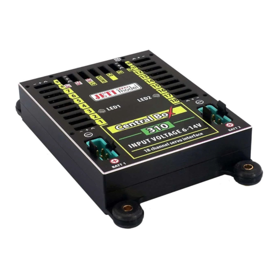
2.2 Central Box 320 • Central Box 320 has 18 outputs for servos (support of DITEX TD telemetry servos) with individual overload protection. Each of the outputs can be operated in these modes: - servo output (default setting) - Digital output - Digital input - Ditex •... - Page 8 • BATT1 and BATT2 – MPX connectors for connecting batteries to power the servos and receivers connected to the Central Box. RC Switch Magnetic Switch LED1 LED2 INPUT VOLTAGE 6-14V 18 channel protected servo interface Pic. 1: Description Central Boxu 310/320 7 EN...
-
Page 9: Magnetic Switch
Central Box 310/320 by the interconnection cable from normal Master port on the magnetic switch to a slot labeled "SWITCH" on the Central Box 310/320. To turn on the Central Box using the magnetic switch it is necessary to... -
Page 10: Connection
Central Box and these other components. 3.1 Power supply of Central Box 310/320 The Central Box 310/320 can only be powered from batteries connected to BATT1 or BATT2. When selecting the power supply it is necessary to follow the power requirements and the number of the servos you use. - Page 11 safely use batteries of different capacity, number of cells, and chemistry type. If the power for the Central Box is provided only from one battery, it can be connected via either the BATT1 or BATT2 input. RC Switch Rsat 900 NG (R3) Rsat2 (R1) E1/E2 SATELLITE RECEIVER...
-
Page 12: Overload Protection Of Servos (Central Box 320)
Be aware of the performance of the fuse is strongly temperature dependent. If the ambient temperature is high (more than 50°C) we recommend using the Central Box 310. The same recommendation applies for the mechanical connection of the several servos. -
Page 13: Connecting Central Box - Ex Bus
- to use a Y cable (connecting two servos to one output) 3.3 Connecting Central Box – EX Bus Receivers can be connected to the Central Box 310/320 using the R1, R2 and E1/R3 inputs. Input E1/R3 it's necessary to set to a Receiver. - Page 14 SATELLITE RECEIVER Ext. 900 NG Rsat2 (R2) Magnetic switch Ext. LED1 LED2 Input Input Voltage Voltage INPUT VOLTAGE 6-14V BATT1 BATT2 18 channel protected servo interface Fig. 5: Block diagram of Central Box 310/320 connection - EX Bus variant 13 EN...
-
Page 15: Alternative Functions - Digital Inp
3.4 Alternative functions – digital input Using the pin as an input is useful for simple feedback, without the use of telemetry sensors. For example: if you attach limit switches to retractable gear, you can have feedback about its condition during the flight. The condition of the digital inputs is sent via EX telemetry and the user can assign sounds or alarms to the events. -
Page 16: Alternative Functions - Digital Output
3.5 Alternative functions – digital output In the digital output mode, only the logical level 1 or 0 is generated on the port configured this way. The value of this output is reflecting the assigned output channel and its level. If the servo position of the specified receiver channel is lower than 0%, i.e. -
Page 17: Configuration Via Jetibox
4 Configuration via JETIBOX After connecting to the Central Box 310/320 (output E4), a start- up screen appears that contains identification of the device in the first line of the JETIBOX display. The second line contains the data showing the consumed capacity of batteries. -
Page 18: Minimum / Maximum Values
Central Box • R3: how long was the signal from the third receiver available to the Central Box 310/320 Statistics of the received signal expressed as a percentage • R1: what percentage of the total operating time was the signal from the primary receiver available to the Central Box •... -
Page 19: Setting
• R3: what percentage of the total operating time was the signal from the third receiver available to the Central Box 310/320 • Over-I Monitor (CB320) - indication of servo output during the operating time of the Central Box; (-) output is fine (x) the output is overloaded 4.3 Setting... -
Page 20: Out Pin Set
more than 80ms the Central Box switches to another active receiver. - Mixing – The Central Box combines data from all active receiver inputs and uses it for servos on the packet-by-packet basis. This strategy is available only if receivers are connected to the Central Box via EX Bus. - Page 21 • SetInChannel – assigns the input channel (marked as Chx) to a specific output (marked as Yx) • Reverse – reverses the output direction • Signal Fault - setting behavior of the receiver in case of signal loss • hold - repeats the last valid deflection command before signal loss •...
-
Page 22: Alarms
Central Box. • Language Setup - (Central Box 310/320) Language of the menu in Jetibox • PresetToSetup – pushing arrows R and L (right and left) together leads to loading the default settings of the Central •... -
Page 23: Configuration Via The Dc/Ds Transmitter
Configuration via the DC/DS transmitter The Central Box can be configured by a DC/DS transmitter via the Device Explorer menu. It is necessary to follow these rules for configuring the Central Box via transmitter: - Receiver firmware version Duplex (Rx FW 3.25 or REX FW 1.14) and newer (with setting Output mode->EX Bus) - The receiver must be connected to the Central Box via EX Bus - Transmitter firmware version 5.06 and newer + the device... -
Page 24: Setting
5.1 Setting • Output Period – setting the output signals period (default: Auto synchronous mode with the transmitter). This parameter significantly affects the behaviour of the servos. For * servos the reaction (response) accelerates and the power consumption is higher when the values for the output period are lower. This can lead to vibration in some servos if the values are set too low. -
Page 25: Alternate Functions Of Pins
Please note that the switch over strategy for ports configured as EX Bus output is kept the same as in the Timeout (150ms) mode. Fig. 10: Device Explorer-General Settings 5.2 Alternate functions of pins Overall setting of alternate functions for individual pins of the Central Box. -
Page 26: Servo Fail-Safe
•Telemetry input - input for connecting telemetry sensor with automatic detection of the connected EX Bus sensor • EX Bus – data output sending channel positions, telemetry, and device configuration • Ditex – support of telemetry DITEX servos Fig. 11 5.3 Servo Fail-Safe In all connected receivers we recommend disable Fail-Safe and set it in the Central Box only. -
Page 27: Servo Output Mapping
• Fail-Safe: generates pre-set servo position (value) if signal loss is detected. Can be programmed with slowdown (Speed) The Fail-Safe position can be immediately applied to the Central Box output if the cursor is on the „Value" menu item and you push the F4 function key. -
Page 28: Telemetry
5.5 Telemetry • Temp. – actual temperature of the Central Box • Shorted outputs No.( CB320 only) – actual number of overloaded outputs • Voltage – actual voltage of individual outputs of the Central Box • Current – actual current drawn from the battery •... -
Page 29: Reset To Factory Settings
• Clear Now – allows you to immediately clear the recorded battery capacity and minimum/maximum values in the Central Box. Fo r d e s c r i p t i o n o f i n d i v i d u a l i t e m s, s e e t h e c h a p t e r Minimum/Maximum values. -
Page 30: Firmware Update
Firmware update Central Box allows firmware update via a PC. The update is performed using the JETI USBa (USB adapter). The procedure is as shown below: On the manufacturer internet pages (www.jetimodel.com), under „Support", you will find an Jeti Studio program with the most recent firmware. -
Page 31: Safety Precautions For Working With Magnets
Safety precautions for working with magnets Because the Central Box is put into operation via magnet, it is necessary to follow safety precautions for handling magnets. The magnet is mounted in a hard aluminium carrier. Keep the magnetic key a safe distance from all devices that could be damaged by the magnet, such as TV, credit cards, computers, etc. -
Page 32: Technical Specifications Of The Central Box
In case you are not sure about the setup or some functions of the product, do not hesitate to contact our technical support. You can contact either your dealer, or directly the manufacturer JETI model s.r.o.. For further information see our webpages www.jetimodel.com. 31 EN... - Page 33 EU Directive EMC 2014/30/EU, RoHS 2011/65/EU and (EU) 2015/863 This declaration of conformity is issued under the sole responsibility of the manufacturer. Producer: JETI model s.r.o. Lomená 1530, 742 58 Příbor, Česká republika IČ 26825147 Declares, that the product...
- Page 34 E l e k t r i c k á z a ř í z e n í o p a t ř e n á symbolem přeškrtnuté popelnice nesmějí být vyhazována do běžného domácího odpadu, namísto toho je n u t n o j e o d e v z d a t v e specializovaném zařízení...
- Page 36 JETI model s.r.o. Lomená 1530, 742 58 Příbor Czech Republic www.jetimodel.com info@jetimodel.cz...
Need help?
Do you have a question about the Central box 310 and is the answer not in the manual?
Questions and answers