Table of Contents
Advertisement
Quick Links
Advertisement
Table of Contents

Summary of Contents for Rotech ANSI Series
- Page 1 INSTALLATION, OPERATION & MAINTENANCE MANUAL ANSI Pump Series...
-
Page 2: Warranty Clause | Limited Liability
Pumps manufactured & assembled by Rotech covered by warranty for free of manufacturing defects for a period not exceed- ing twelve months from the date of shipment from our Plant/warehouse. This warranty will be limited and subject to Rotech authorisation /approval. -
Page 3: Table Of Contents
CONTENTS WARRANTY CLAUSE | LIMITED LIABILITY INTRODUCTION OF PUMP Pump Safety Tools and Procedure Model Relationship Chart RECEIPT AND STORAGE Receipt of Pump and Equipment Storage of Pump and Equipment INSTALLATION Preparation Foundation Coupling Alignment Procedure Piping OPERATION Preparation for start-up Initial Starting Final Alignment Stuffing Box... - Page 4 APPENDIX APPENDIX 1 Centrifugal pump troubleshooting Maintenance and Repair Assembly Procedures APPENDIX 2 Interchangeability of ANSI 1196 Series pumps STR Exploded view and part list MTR Exploded view and part list LTR Exploded view and part list APPENDIX 3 Maintenance instructions for Inpro/Seal® “VBX” bearing isolators Details of Operations Disassembly Procedures Installation Procedures...
-
Page 5: Introduction Of Pump
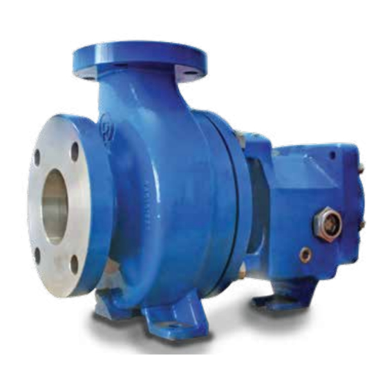
INTRODUCTION OF PUMP Rotech’s 1196 SERIES ANSI chemical process centrifugal pumps are designed for pumping various types of chemicals, hydrocarbon, slurries and other liquid. This pump has back pull out design enable to pull out from operation without disturbing piping. -
Page 6: Model Relationship Chart
MODEL RELATIONSHIP CHART 1196 1796 1196 LF CASING # Self-venting # Self-venting # Self-venting # Top centerline discharge # Centerline discharge # Top centerline discharge # Integral foot support # Fully confined gasket # Fully confined gasket # Integral foot support # Integral foot support # Integrally cast priming chamber permits self-priming... -
Page 7: Receipt And Storage
3. Check pump crate and pump & other equipment is in good condition and did not damage in transportation. If there is any damage, immediately report to shipper Rotech Distributor or your supplier. 4. Use proper procedure unloading pump and equipment from truck. -
Page 8: Installation
INSTALLATION PREPARATION When preparing your pump for installation, Please make sure the discharge and suction connections must be clean and free of anything that might prohibit a tight connection. This is especially important on the suction, air leaks can cause a pump to operate poorly or to lose prime completely. -
Page 9: Coupling Alignment Procedure
1. Apply Anti-seizing compound on jack screw to allow for pads to zero in both directions. easy removal after the grout has cured. 6. Turn down the center jack screws until they are resting 2. Cut 6 or 8 round plates from barstock to set the jack on their metal plates. -
Page 10: Piping
ALIGNMENT TROUBLESHOOTING Problem Probable Cause Solution The bolts holding the Loosen pump hold down bolts & slide pump & driver until driver feet are bound. horizontal alignment is achieved. Cannot obtain horizontal alignment, angular of parallel Baseplate not leveled Determine which corner(s) of baseplate are high or low & properly, probably twisted. - Page 11 SUCTION PIPING: SUCTION HEAD/SUCTION CONDITIONS 1. Properly installed suction piping is necessary for 1. An isolation valve should be installed in the suction trouble-free pump operation. Flush suction piping before pipe at least four diameters from the suction to allow connection to the pump.
-
Page 12: Operation
2. Gate valve in discharge line must be closed. 3. After pump is primed, valves between vacuum pump & 1. Lock out power to motor to prevent accidental rotation Rotech pump must be closed. & physical injury. 4. On pumps using packing it may be necessary to 2. -
Page 13: Initial Starting
INITIAL STARTING enough for the pump and motor to reach operating temperature. 1. The gate valve in the discharge line should be closed & 2. Check alignment while unit is still hot. gradually opened as the motor reaches full speed 3. -
Page 14: Impeller Clearance
Storage, Assembly & Disassembly of Mechanical FEELER GAUGE TECHNIQUE Seal: 1. Lock out power to the pump driver. 2. Remove the coupling guard. Read, understand & follow the manufacture’s installa- 3. Loosen jacking bolts (370D) and jam nuts (423). tion, operation and maintenance instructions. 4. - Page 15 370C 370D Fig. 8 DIAL INDICATOR TECHNIQUE 7. Tighten the jack bolts (370D) evenly until they contact the frame. Continue to tighten until the dial indicator reads the proper clearance. 1. Lock out power to the pump driver. 8. Tighten bearing housing bolts (370C) evenly; then 2.
-
Page 16: Priming
Priming 7. Adjust the discharge valve as needed while checking piping for leaks. Prior to starting a centrifugal pump, it is imperative that 8. Check mechanical operation of the pump and motor. you prime the pump by flooding the suction piping and casing with fluid. -
Page 17: Maintenance
The bearing temperature will usually rise after regreasing due to an excess of grease. Temperatures should return All pumps are lubricated at the Rotech plant and should to normal after the pump has purged the excess grease. not require additional lubrication for approximately 1200 Never mix greases of different consistency or thickener. -
Page 18: Mechanical Seals
8. Reinstall impeller following same method previously mately 30 drops per minute to leak from the packing. used. 7. When specified, Rotech can provide means of lubricat- 9. Mount seal gland to stem plate. ing the shaft and packing through a lantern ring by... -
Page 19: Assembly Troubleshooting
ALL MODELS 6. Check total travel of impeller in the casing, if it is more than .030 in. improper parts or installation or too much 1. Clean fits between rotating assembly and impeller pipe strain is present. Determine cause and correct housing (26). - Page 20 APPENDIX APPENDIX 1 Centrifugal pump troubleshooting The following table provides possible solutions for symptoms that you may encounter with your centrifugal pump. ! WARNING ! Before attempting to service the pump: 1. Follow the shut down procedures. 2. Lock out the power source. 3.
- Page 21 ! WARNING ! Pump parts are heavy. Use proper lifting methods to avoid personal injury. 4. Place lifting sling through frame to ensure safe handling during disassembly / assembly. 5. Remove bolts (370) holding the frame adapter (108) to casing (100). 6.
- Page 22 13. Slide shaft assembly, with housing, out of bearing frame. 14. On the STR and MTR, remove the bearing housing snap ring. On the LTR and XLR, remove bearing cover screws and remove bearing cover. Then remove the bearing housing by tapping with a rubber hammer. 15.
- Page 23 1. Clean the bearing frame and inspect all tapped holes. Chase as needed. 2. Install oil fill plug, oil sight glass, and frame lubrication plugs. 3. Attach bearing frame foot with bolts, where applicable. 4. On the LTR model, install oil ring on shaft, if removed. Oil ring is a press fit onto shaft. NOTE: Use proper size drive tool to prevent damage.
- Page 24 c. Rotate shaft 360 degrees. It should be free. NOTE: These steps do not apply to the 6" STR Model. 16. Set frame and adapter upright. Clamp to bench for safety as assembly continues. 17. Install inboard bearing labyrinth seal in adapter frame. Make sure that the seal’s drain slots face down. Follow Mainte- nance instructions in Appendix 5.
- Page 25 APPENDIX 2 INTERCHANGEABILITY OF ANSI 1196 SERIES PUMP 1 x 1.5 - 6 1.5 x 3 - 6 MODEL 1196 2 x 3 - 6 1 3/8” Shaft Dia 1 x 1.5 - 8 MAX BHP - 40 HP 1.5 x 3 - 8 3 x 4 - 7 2 x 3 - 8 1 x 2 - 10...
- Page 26 STR EXPLODED VIEW & PART LIST-1196 332A 333A 112A MATERIAL OF CONSTRUCTIONS PART PART DESCRIPTION WCB / Carbon Steel SS304 316SS CD4MCu Alloy20 Hastelloy B & C Nos. Casing WCB / Carbon Steel SS304 316SS CD4MCu Alloy20 Hastelloy Impeller WCB / Carbon Steel SS304 316SS CD4MCu...
- Page 27 STR SECTIONAL VIEW-1196 112A 332A 412A 333A 168A...
- Page 28 MTR EXPLODED VIEW & PART LIST-1196 112A 332A 412A 333A 370H MATERIAL OF CONSTRUCTIONS PART PART DESCRIPTION WCB / Carbon Steel SS304 SS316 CD4MCu Alloy20 Hastelloy B & C Nos. Casing WCB / Carbon Iron SS304 SS316 CD4MCu Alloy20 Hastelloy B & C Impeller WCB / SS316 SS316...
- Page 29 MTR / LTR SECTIONAL VIEW-1196 370H 168A 112A 332A 412A 333A 360F...
- Page 30 XLR EXPLODED VIEW & PART LIST-1196 112A 332A 412A 333A 370H MATERIAL OF CONSTRUCTIONS PART PART DESCRIPTION WCB / Carbon Steel SS304 SS316 CD4MCu Alloy20 Hastelloy B & C Nos. Casing WCB / Carbon Iron SS304 SS316 CD4MCu Alloy20 Hastelloy B & C Impeller WCB / SS316 SS316...
- Page 31 XLR SECTIONAL VIEW-1196 370H 168A 112A 332A 412A 333A 360F...
- Page 32 STR EXPLODED VIEW & PART LIST-1196LF 333A 112A 332A MATERIAL OF CONSTRUCTIONS PART PART DESCRIPTION WCB / Carbon Steel SS304 316SS CD4MCu Alloy20 Hastelloy B & C Nos. Casing WCB / Carbon Steel SS304 316SS CD4MCu Alloy20 Hastelloy Impeller WCB / Carbon Steel SS304 316SS CD4MCu...
- Page 33 STR SECTIONAL VIEW-1196LF 112A 332A 412A 333A 168A...
- Page 34 MTR EXPLODED VIEW & PART LIST-1196LF 112A 332A 412A 333A 370H MATERIAL OF CONSTRUCTIONS PART PART DESCRIPTION WCB / Carbon Steel SS304 SS316 CD4MCu Alloy20 Hastelloy B & C Nos. Casing WCB / Carbon Iron SS304 SS316 CD4MCu Alloy20 Hastelloy B & C Impeller WCB / SS316 SS316...
- Page 35 MTR / LTR SECTIONAL VIEW-1196LF 370H 168A 112A 332A 412A 333A 360F...
- Page 36 XLR EXPLODED VIEW & PART LIST-1196LF 112A 332A 412A 333A 370H MATERIAL OF CONSTRUCTIONS PART PART DESCRIPTION WCB / Carbon Steel SS304 SS316 CD4MCu Alloy20 Hastelloy B & C Nos. Casing WCB / Carbon Iron SS304 SS316 CD4MCu Alloy20 Hastelloy B & C Impeller WCB / SS316 SS316...
- Page 37 XLR SECTIONAL VIEW-1196LF 370H 168A 112A 332A 412A 333A 360F...
- Page 38 SECTIONAL VIEW & PART LIST-1796 333A 108 332A 469B 358A MTR/LTR...
- Page 39 PART LIST-1796 MATERIAL OF CONSTRUCTIONS Item PART NAME Ductile Hastelloy Nos. 316 SS CD4MCu Alloy 20 Titanium Iron B & C Casing Ductile Iron 316 SS CD4MCu Alloy 20 Hastelloy Titanium Impeller Ductile Iron 316 SS CD4MCu Alloy 20 Hastelloy Titanium Lantern Ring Glass Filled Teflon*...
- Page 40 APPENDIX 3 MAINTENANCE INSTRUCTIONS FOR INPRO/SEAL® “VBX” BEARING ISOLATORS Details of Operations The Inpro Bearing Isolator is a Labyrinth type seal, which performs two functions: 1. Maintains the clean oil in the bearing housing. 2. Keeps contaminates from entering the bearing housing. The unit is comprised of three major components: the rotor, the stator, and the “VBX”...
- Page 41 APPENDIX 4 - DIMENSION DATA ANSI 1196 MODEL DISCHARGE SUCTION Bare Pump Pump ANSI Discharge Suction Pump Frame Size Designation Size Size Weight LBS. 1x1.5-6 1.5x3-6 2x3-6 6.5 (165) 5.25 (133) 13.5 (343) 4 (102) 7.25 3.75 (95) 0.875 1x1.5-8 1.5x3-8 3x4-7 11 (280)
- Page 42 ANSI 1196LF MODEL DISCHARGE SUCTION Bare Pump Model Size Discharge Suction Weight LBs. 1 x 1.5 - 4 6.5 (165) 13.5 (343) 4 (102) 5.25 (133) 3.75 (95) 1 x 1.5 - 8 6.5 (165) 13.5 (343) 4 (102) 5.25 (133) 3.75 (95) 1 x 2 -10 8.5 (216) 19.5 (495)
- Page 43 ANSI 1796 MODEL 3.75” (95) SUCTION DISCHARGE Bare Pump Group Pump Size Discharge Suction Weight LBS. (Kg) 1 x 1 1/2 - 6 1 1/2 7 1/4 (184) 15 1/2 (127) 5 (127) 7 1/2 (191) 4 (102) 170 (77) 1 1/2 x 1 1/2 - 8 1 1/2 1 1/2...
- Page 44 BASEPLATE RELATED DIMENSIONS ANSI 1196 & 1196LF MODEL HHØ Hole Pump Frame Baseplate No. Max Motor Frame 32 1/2 1 1/4 4 1/2 4 1/2 36 1/2 1 1/4 3 1/4 4 1/2 43 1/2 1 1/4 4 1/8 4 1/2 4 1/2 42 1/2 1 1/4...
- Page 45 APPENDIX 5 CONSTRUCTION DETAILS Diameter at Impeller (19) (25) 1.25 (32) (38) Diameter in Stuffing Box 1.375 (35) 1.75 (45) 2.125 (54) (64) (Solid Shaft Const.) Diameter between Bearings (38) 2.125 (54) (64) 3.125 (79) Diameter at Coupling .875 (22) 1.125 (29) 1.875...
- Page 46 Stuffing Box Related Dimensions Packing Lantern Pump Ring # of Frame B.C. Obstruction Size Rings width 2.00 2.12 3.25 3/8-18 UNC 0.97 1/4-18 NPT 2.39 1.40 2.18 5/16 7/16 2.50 2.62 4.12 1/2-13 UNC 1.56 3/8-18 NPT 3.01 1.78 2.65 3.00 2.78 2.62...
- Page 47 Bearing Fits & Tolerances Shaft O. D. 1.3785 (35.013) 1.7722 (45.013) 2.1660 (55.015) 2.5597 (65.015) Inboard 1.3781 (35.002) 1.7718 (45.002) 2.1655 (55.002) 2.5592 (65.002) 0.0010 (0.025) tight 0.0010 (0.025) tight 0.0012 (0.030) tight 0.0012 (0.030) tight Clearance 0.0001 (0.002) tight 0.0001 (0.002) tight 0.0001 (0.002) tight 0.0001 (0.002) tight...
- Page 48 Before assembling or disassembling the coupling guard, de-energize the motor, lock out the motor controller/starter, and place a caution tag at the starter indicating that it is disconnected. Before resuming normal pump operation, replace the coupling guard. Rotech Pump assumes no liability when these procedures are avoided.
- Page 49 Gaurd Half End Plate Fig. B 3. After placing the coupling guard half (pump end) around the pump end plate, secure it with a bolt, nut and two (2) washers through the round hole in the front end of the guard half as shown in Figure C. Tighten securely. Fig.
- Page 50 Gaurd Half Drive Fig. D 5. Place the end plate (driver end) over the motor shaft as shown in Figure E. Position the end plate in the annular groove at the rear of the coupling guard half (driver end) & secure it with a bolt, nut, & two (2) washers through the round hole at the rear of the guard half.
- Page 51 Fig. F Disassembly Procedures It is necessary to remove the coupling guard for certain pump maintenance and adjustments, such as coupling adjustment, impeller clearance adjustment, and so forth. Replace the coupling guard after completing maintenance. DO NOT resume normal pump operation while the coupling guard is removed. 1.
- Page 52 1320 Britannia Road East, Mississauge, Ontario, Canada. L4W 1C8 Phone: (905) 461 - 9617 | Fax: (905) 461 - 9618 Toll Free: 1-866-217-PUMP (7867) Email: sales@rotechpumps.com | www.rotechpumps.com...
Need help?
Do you have a question about the ANSI Series and is the answer not in the manual?
Questions and answers