Advertisement
Quick Links
Power supply
Always use a UL or CE marked wall power supply with the included splitter cables. Use a wall power
supply that can deliver enough current for your application. For best results, use a 5.1 volt power
supply to avoid low voltage warning on the display. The official Raspberry Pi power supply is recom-
mended.
The splitter cables are only for use with the Raspberry Pi and Official Raspberry Pi display.
Raspberry Pi 2 and 3
5.1 V 2.5A Micro USB Power
supply recommended
Raspberry Pi 4
5.1 V 3A USB-C Power
supply recommended
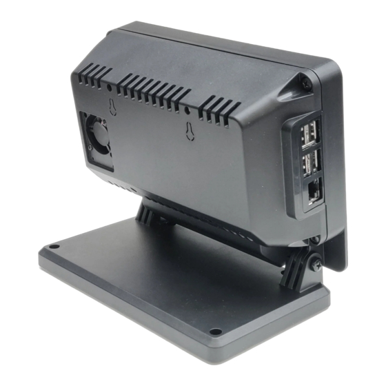
Step 1
Please choose which splitter works your Raspberry Pi model. Insert the female end into the back cover
as shown below. The cable can be assembled in either of two positions. Option 1 extends further out for
easier access. Option 2 is the more compact option.
Assembly instructions
Questions or missing parts? Email
Drawings and CAD files are available at smarticase.com
Micro USB input
USB-C input
option 1
info@smarticase.com
Micro USB (Pi 2 and 3)
Micro USB (display)
USB-C (Pi 4)
Micro USB (display)
option 2
Advertisement

Summary of Contents for Smarti Pi Touch Pro
- Page 1 Assembly instructions Questions or missing parts? Email info@smarticase.com Drawings and CAD files are available at smarticase.com Power supply Always use a UL or CE marked wall power supply with the included splitter cables. Use a wall power supply that can deliver enough current for your application. For best results, use a 5.1 volt power supply to avoid low voltage warning on the display.
- Page 2 Step 2 Use two of the small black screws to secure the small plastic retaining part to the back cover. This will hold the power cable in the case. Do not overtighten the screws! Step 3 Assemble the metal base on the bottom of the plastic base. The metal base can only properly assemble onto the base one way.
- Page 3 If you do not have a metal base, attached the four adhesive pads to the plastic base. Step 4 Assemble one of the white ribbon cables with the contacts facing up to the display connection on the display board. If using the fan, connect the red jumper lead that came with the display to the 5v connectionon the display board GPIO pins and the black jumper lead to the ground pin.
- Page 4 Step 5 Attach the display to the housing using the green screws as shown below. Feed the white ribbon cable through the slot in the center of the housing. Feed the fan power leads through the hole at the top.
- Page 5 Step 6 If using the port blocking part, from the back side cut out the desired ports with a utility knife. Two parts are included. One for Pi 2/3 and one for Pi 4. Step 7 Assemble the port block part and the Raspberry Pi at the same time to the display housing. Use the standoffs that were removed in step 4 to hold the Raspberry pi in place.
- Page 6 You can choose to mount the Raspberry Pi in the other set of brass inserts if you wish. Although you won’t have access to the USB and ethernet ports. Step 8 Assemble the camera cover part with two of the small black screws if you choose to not use the camera. If you choose to use the camera, the Official Raspberry Pi camera can be assemble into the these holes with two of the small black screws...
- Page 7 Step 9 Assemble the display housing to the stand with the large black screws and nuts. DO NOT OVERTIGHTEN. Loosely attach the screws at this point. Step 10 If you choose to not use the fan, the small door can be assembled into the hole in the back cover and attach with two of the small black screws.
- Page 8 Step 11 If you choose to use the fan , attached the small rubber vibration mounts to the holes in the back cover as shown below. Push the small end of the mount through the back cover from the outside. Then pull it through the cover as shown.
- Page 9 Step 13 Attach the power leads from the display to the red and black on the fan. Step 14 Assemble the back cover to the display housing with the four black screws. The port blocking part should have tabs that fit inside the housing and cover.
- Page 10 Step 15 Adjust the angle of the display to suit you needs. Then tighten the pivot screws. DO NOT OVERTIGHTEN. Tighten the screws just enough to hold the display in place.
- Page 11 Adhesive front panel If the case came with a blank adhesive panel for the front, this can be used to permanently hide the camera hole. Align the label with the small edge in the plastic below the display. Do not have the plastic camera cover part installed, as this is not needed if using the adhesive panel.
Need help?
Do you have a question about the Pi Touch Pro and is the answer not in the manual?
Questions and answers