Advertisement
Available languages
Available languages
Quick Links
OPERATING INSTRUCTIONS
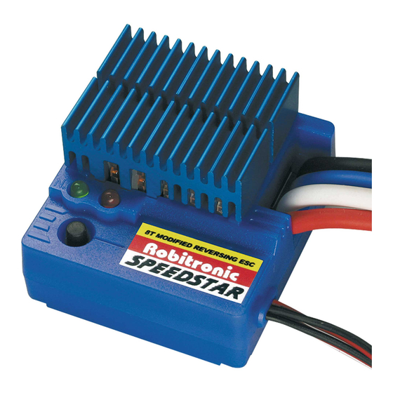
SPEEDSTAR
8T MODIFIED ESC
The following instructions will help you get
trouble-free operation from your ESC. These
simple steps will allow your ESC to achieve
maximum performance and minimize the chance
of problems due to incorrect installation. Consult
the specifications at the bottom of the box listed
below for limitations for this ESC.
INSTALLATION
• Keep the speed controller and all power wires at least 2cm from the radio
receiver and receiver antenna.
• To securely mount the speedo to the chassis of your car using always double
sided (servo) tape.
• Always install a motor noise killer capacitor.
RADIO SETUP
Before you begin this step, the ESC should be connected to the throttle channel on the
receiver, the transmitter should already be adjusted, and the ESC switch should be in the off
position.
1) Connect the battery pack to the ESC, turn on the Transmitter, then the ESC.
2) NEUTRAL POINT: Leave the throttle trigger in the neutral
position. Press and hold the ESC's push button until the green
LED begins to flash, then release the button.
3) FULL THROTTLE: Move the throttle trigger during the green
LED flashes to full throttle and hold until the red LED illuminates
(motor will not operate in set up mode). If the red LED flashes
you must restart at Step 1) and move quicker from Step 2) to
Step 3).
4) FULL REVERSE: Move the throttle trigger to full brake/reverse
and hold until both the red and green LEDs illuminate.
5) ABS BRAKES: Return the throttle trigger to neutral. The green LED will flash briefly,
followed by both the red and green LEDs oscillating after about 3 seconds, during this time
you are able to setup the ABS brake..
a) To activate ABS brakes: Move the throttle trigger to either full throttle or full reverse
(while the LEDs are oscillating), then return to neutral. The red LED will flash to confirm
ABS brakes are active.
b) To de-activate ABS brakes: DO NOT move the throttle trigger (leave in neutral position)
when the LEDs oscillate in this step.
6) The ESC is now set for operation, confirmed by the green LED remaining on.
7) If the motor operates in reverse when applying forward throttle, the throttle reversing
switch on the transmitter must be moved to the opposite position.
TRACTION CONTROL
The Acceleration, or traction control function provides 3 optional time delays which control
how quickly full forward speed is delivered to the motor after full deflection is given to throttle
trigger. This allows the ESC to be customized to personal preferences or certain track and
model conditions.
To set the acceleration / traction control:
1) With the transmitter in the neutral position, press and hold the ESC's setupbutton for
3 seconds. The green LED will flash, followed by a flashing red LED.
2) Release the setupbutton, and choose from one of three acceleration time delays as follows:
a) After one second the red LED will blink ONCE. Press and release the setupbutton at
this time to set a delay of 0.09 seconds. This is often the desirable delay for normal
race tracks.
b) After two seconds the red LED will blink TWICE. Press and release the setupbutton at
this time to set a delay of 0.16 seconds.
c) After three seconds the red LED will blink THREE times. Press and release the setup
button at this time to set a time delay of 0.27 seconds. This is often the desirable delay
for slick tracks.
Robitronic Electronic Ges.m.b.H. -
RS144
Neutral
N
Full
Throttle
N
N
Guntherstrasse 11, 1150 Vienna, Austria - Tel: +43-1-982 09 20, Fax: +43-1-982 09 21, www.robitronic.com
CONNECTION
Green LED
Red LED
Setup
Button
REVERSE DELAY & REVERSE LOCKOUT
A time delay can be set for changing the direcion of motor travel from
forward to reverse. This delay helps to prevent damage to gear
assemblies that can result from slamming the motor from high speed
forward movement directly to reverse. the reverse direction control for
this ESC can also be completely disabled or "locked-out". Many races
require ESCs be used which do not have reverse function.
Follow these steps to set reverse delay or reverse lockout:
1) With the transmitter throttle in the neutral position, press and hold
the ESC's setupbutton for 5 seconds. The green and red LEDs will
flash.
2) Release the setupbutton, and choose from one of two reverse time
delays or reverse lockout as follows:
a) After one second the green and red LED will blink ONCE. Press and
release the setupbutton at this time to set a delay of 0.3 seconds.
This is often the desirable delay for normal race tracks.
b) After two seconds, the green and red LED will blink TWICE. Press
and release the setupbutton at this time to set a delay of 0.8
seconds.
Full
Brake
c) After three seconds the green and red LED will blink THREE times.
Press and release the setupbutton at this time to completely
lockout or shut off reverse.
!
WARNING
• Never leave your RC model unsupervised with the battery connected.
If a fault should occur, this could cause a fire in the model and
threaten anything in the vicinity.
• Never use more than 7 cells (8.4 volts) in the battery pack.
• The speed controller and all electronic components must not be
allowed to contact with water. Do not run your RC model in the rain.
• Never reverse the battery polarity. Reverse connection will
immediately destroy the controller. Use only polarised connectors.
• All cables and connectors must be effectively insulated. Short
circuits can damage your speed controller.
• When a motor is connected to the controller, you must not connect a
separate battery and run the motor. This will damage the controller.
• Always turn your transmitter on first and off last. If you start your car
first, you will lose control of the car and an extremely dangerous
situation may occur.
• Be careful not to touch the heat sink during use as it can become very
hot.
• Not suitable for children under 14 years. This unit is not a toy.
THERMAL CUTOFF PROTECTION
This ESC has built-in circuitry to sense an excessive heating condition
caused by current overload. If the operating temperaure exceeds 100°
Celsius, the unit will automatically shut down, as indicated by flashing
red
and
green
components and prevent permanent damage from occurring. The ESC
can again be used once the internal temperature returns to an
acceptable level, as indicated by change in the setup LEDs.
Battery connector
Black (-)
Red (+)
Black (-)
Motor connector
Blue (-)
White (+)
Red (+)
Power switch
LEDs.
This
is
to
protect
Receiver
connector
(channel 2)
all
on-board
Advertisement

Related Manuals for Robitronic Speedstar

Summary of Contents for Robitronic Speedstar
- Page 1 0.27 seconds. This is often the desirable delay for slick tracks. acceptable level, as indicated by change in the setup LEDs. Robitronic Electronic Ges.m.b.H. - Guntherstrasse 11, 1150 Vienna, Austria - Tel: +43-1-982 09 20, Fax: +43-1-982 09 21, www.robitronic.com...
- Page 2 Die LEDs wechseln wieder zu den normalen das Programm mit 0.27 Sekunden. Diese Einstellung ist für rutschige Strecken geeignet. Einstellungen zurück. Robitronic Electronic Ges.m.b.H. - Guntherstrasse 11, 1150 Wien, Österreich - Tel: +43-1-982 09 20, Fax: +43-1-982 09 21, www.robitronic.com...
Need help?
Do you have a question about the Speedstar and is the answer not in the manual?
Questions and answers