Table of Contents
Advertisement
Advertisement
Table of Contents

Related Manuals for Asus ROG STRIX B365-G GAMING


Summary of Contents for Asus ROG STRIX B365-G GAMING
- Page 1 ROG STRIX B365-G GAMING...
- Page 2 Product warranty or service will not be extended if: (1) the product is repaired, modified or altered, unless such repair, modification of alteration is authorized in writing by ASUS; or (2) the serial number of the product is defaced or missing.
-
Page 3: Table Of Contents
Contents Safety information ...................... vi About this guide ......................vii ROG STRIX B365-G GAMING specifications summary .......... ix Package contents ..................... xiii Installation tools and components ................. xiv Chapter 1: Product Introduction Motherboard overview ................1-1 1.1.1 Before you proceed ..............1-1 1.1.2... - Page 4 3.6.11 HDD/SSD SMART Information ..........3-17 Monitor menu ................... 3-17 Boot menu ....................3-18 Tool menu ....................3-19 3.9.1 ASUS EZ Flash 3 Utility ............3-19 3.9.2 Secure Erase ................3-20 3.9.3 ASUS User Profile..............3-21 3.9.4 ASUS SPD Information ............. 3-21 3.9.5...
- Page 5 Chapter 4: RAID Support RAID configurations .................. 4-1 4.1.1 RAID definitions ................4-1 Appendix Q-Code table ......................A-1 Notices ........................A-5 ASUS contact information ..................A-9...
-
Page 6: Safety Information
Safety information Electrical safety • To prevent electrical shock hazard, disconnect the power cable from the electrical outlet before relocating the system. • When adding or removing devices to or from the system, ensure that the power cables for the devices are unplugged before the signal cables are connected. If possible, disconnect all power cables from the existing system before you add a device. -
Page 7: About This Guide
Refer to the following sources for additional information and for product and software updates. ASUS website The ASUS website (www.asus.com) provides updated information on ASUS hardware and software products. Optional documentation Your product package may include optional documentation, such as warranty flyers, that may have been added by your dealer. - Page 8 Conventions used in this guide To ensure that you perform certain tasks properly, take note of the following symbols used throughout this manual. DANGER/WARNING: Information to prevent injury to yourself when trying to complete a task. CAUTION: Information to prevent damage to the components when trying to complete a task.
-
Page 9: Rog Strix B365-G Gaming Specifications Summary
* Hyper DIMM support is subject to the physical characteristics of individual CPUs. * DDR4 2666MHz will run at max. 2666MHz on Intel® 9th / 8th Gen. 6-core or higher processors. * Refer to www.asus.com for the Memory QVL (Qualified Vendors Lists). Integrated Graphics Processor- Intel HD Graphics support ®... - Page 10 ASUS Exclusive Features: - AI Suite 3 - ASUS EPU ASUS Special Features - ASUS UEFI BIOS EZ Mode featuring friendly graphics user interface - ARMOURY CRATE ASUS EZ DIY: - ASUS CrashFree BIOS 3 - ASUS EZ Flash 3...
- Page 11 ROG STRIX B365-G GAMING specifications summary Aura Sync ROG RAMCache III ROG Exclusive ROG GameFirst V Features ROG Overwolf ROG CPU-Z 1 x PS/2 keyboard/mouse combo port(s) 2 x USB 2.0 ports 1 x DVI port 1 x HDMI 1.4b port 2 x USB 3.1 Gen 2 ports (2 x Type-A [Red])
- Page 12 10 64-bit Operating system ® support Micro ATX Form Factor 9.6 inch x 9.6 inch ( 24.4 cm x 24.4 cm ) Form factor Specifications are subject to change without notice. Please refer to the ASUS website for the latest specifications.
-
Page 13: Package Contents
Package contents Check your motherboard package for the following items. Motherboard 1 x ROG STRIX B365-G GAMING motherboard Cables 1 x 2-in-1 SATA 6Gb/s cables 1 x Cable Tie black 1 x ROG Strix Series sticker Accessories 1 x ROG Strix Series Door Hanger 1 x M.2 Screws Package... -
Page 14: Installation Tools And Components
Installation tools and components Intel 1151 CPU ® Intel 1151 compatible CPU Fan ® Phillips (cross) screwdriver PC chassis SATA hard disk drive 1 bag of screws DIMM Power supply unit SATA optical disc drive (optional) Graphics card (optional) The tools and components listed above are not included in the motherboard package. -
Page 15: Chapter 1: Product Introduction
• Before handling components, use a grounded wrist strap or touch a safely grounded object or a metal object, such as the power supply case, to avoid damaging them due to static electricity. • Hold components by the edges to avoid touching the ICs on them. • Whenever you uninstall any component, place it on a grounded antistatic pad or in the bag that came with the component. • Before you install or remove any component, ensure that the ATX power supply is switched off or the power cord is detached from the power supply. Failure to do so may cause severe damage to the motherboard, peripherals, or components. ROG STRIX B365-G GAMING... -
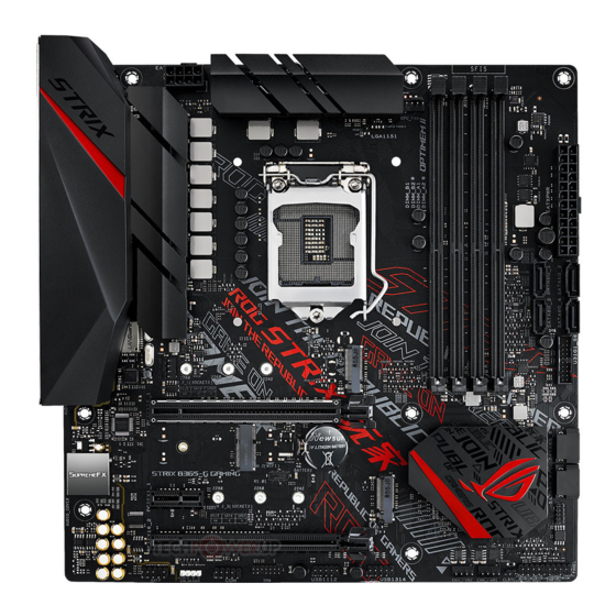
Page 16: Motherboard Layout
1.1.2 Motherboard layout Refer to Internal connectors and Rear I/O connection section for more information. Chapter 1: Product Introduction... - Page 17 Fan and pump connectors 1-15 DIMM slots SATA 6 Gb/s connector 1-10 USB 3.1 Gen 1 connector 1-12 System Panel connector 1-17 Clear RTC RAM jumper USB 2.0 connector 1-12 10. TPM connector 1-11 11. Serial port connector 1-11 12. AURA RGB LED connector 1-14 13. Front Panel Audio connector 1-18 14. M.2 slot 1-13 15. M.2 Wi-Fi slot 1-13 ROG STRIX B365-G GAMING...
-
Page 18: Central Processing Unit (Cpu)
• Ensure that you install the correct CPU designed for LGA1151 socket only. DO NOT install a CPU designed for other sockets on the LGA1151 socket. • The CPU fits in only one correct orientation. DO NOT force the CPU into the socket to prevent bending the connectors on the socket and damaging the CPU. • Ensure that all power cables are unplugged before installing the CPU. • Upon purchase of the motherboard, ensure that the PnP cap is on the socket and the socket contacts are not bent. Contact your retailer immediately if the PnP cap is missing, or if you see any damage to the PnP cap/socket contacts/motherboard components. ASUS will shoulder the cost of repair only if the damage is shipment/ transit-related. • Keep the cap after installing the motherboard. ASUS will process Return Merchandise Authorization (RMA) requests only if the motherboard comes with the cap on the LGA1151 socket. • The product warranty does not cover damage to the socket contacts resulting from incorrect CPU installation/removal, or misplacement/loss/incorrect removal of the PnP cap. Chapter 1: Product Introduction... -
Page 19: System Memory
1.1.4 System memory The motherboard comes with Dual Inline Memory Modules (DIMM) slots designed for DDR4 (Double Data Rate 4) memory modules. A DDR4 memory module is notched differently from a DDR, DDR2, or DDR3 module. DO NOT install a DDR, DDR2, or DDR3 memory module to the DDR4 slot. Recommended memory configurations The recommended memory DIMM slots are marked with an asterix (*). ROG STRIX B365-G GAMING... - Page 20 Memory configurations You may install 2 GB, 4 GB, 8 GB, 16 GB unbuffered and non-ECC DDR4 DIMMs into the DIMM sockets. You may install varying memory sizes in Channel A, and Channel B. The system maps the total size of the lower-sized channel for the quad-channel configuration. Any excess memory from the higher-sized channel is then mapped for single-channel operation. • The default memory operation frequency is dependent on its Serial Presence Detect (SPD), which is the standard way of accessing information from a memory module. Under the default state, some memory modules for overclocking may operate at a lower frequency than the vendor-marked value. • For system stability, use a more efficient memory cooling system to support a full memory load or overclocking condition. • Always install the DIMMS with the same CAS Latency. For an optimum compatibility, we recommend that you install memory modules of the same version or data code (D/C) from the same vendor. Check with the vendor to get the correct memory modules. • Visit the ASUS website for the latest QVL. Chapter 1: Product Introduction...
-
Page 21: Expansion Slots
1.1.5 Expansion slots Unplug the power cord before adding or removing expansion cards. Failure to do so may cause you physical injury and damage motherboard components. ROG STRIX B365-G GAMING... - Page 22 Recommended VGA configuration Slot Description Single VGA PCIe 3.0 x16_1 PCIe 3.0 x1_1 PCIe 3.0 x16_2 • We recommend that you provide sufficient power when running CrossFireX™ mode. • Ensure to connect the 8-pin power plug when running CrossFireX™ mode. • Connect a chassis fan to the chassis fan connectors when using multiple graphics cards for better thermal environment. Chapter 1: Product Introduction...
-
Page 23: Onboard Jumpers
To erase the RTC RAM: Turn OFF the computer and unplug the power cord. Short-circuit pin 1-2 with a metal object or jumper cap for about 5-10 seconds. Plug the power cord and turn ON the computer. Hold down the <Del> key during the boot process and enter BIOS setup to re-enter data. DO NOT short-circuit the pins except when clearing the RTC RAM. Short-circuiting or placing a jumper cap will cause system boot failure! If the steps above do not help, remove the onboard button cell battery and move the jumper again to clear the CMOS RTC RAM data. After clearing the CMOS, reinstall the button cell battery. ROG STRIX B365-G GAMING... -
Page 24: Internal Connectors
SATA 6Gb/s connector The SATA 6Gb/s connector allows you to connect SATA devices such as optical disc drives and hard disk drives via a SATA cable. If you installed SATA storage devices, you can create a RAID 0, 1, 5, and 10 configuration with the Intel Rapid Storage Technology through the onboard Intel B365 chipset. ® ® • The connectors are set to [AHCI Mode] by default. If you intend to create a SATA RAID set using these connectors, set the SATA Mode item in the BIOS to [Intel RST Premium With Intel Optane System Acceleration(RAID)]. • The SATA6G_1 port shares bandwidth with M.2_1 slot when using M.2 SATA mode device. • Before creating a RAID set, refer to the RAID Configuration Guide. You can download the RAID Configuration Guide from the ASUS website. Chapter 1: Product Introduction 1-10... - Page 25 Serial Port connector The Serial (COM) Port connector allows you to connect a serial port module. Connect the serial port module cable to this connector, then install the module to a slot opening on the system chassis. The serial port module is purchased separately. TPM connector The TPM connector allows you to connect a Trusted Platform Module (TPM). A TPM securely stores keys, digital certificates, passwords, data, and also helps enhance network security, protect digital identities, and ensures platform integrity. The TPM is purchased separately. ROG STRIX B365-G GAMING 1-11...
- Page 26 USB 3.1 Gen 1 connector The USB 3.1 Gen 1 connector allows you to connect a USB 3.1 Gen 1 module for additional USB 3.1 Gen 1 ports. The USB 3.1 Gen 1 connector provides data transfer speeds of up to 5 Gb/s. The USB 3.1 Gen 1 module is purchased separately. USB 2.0 connector The USB 2.0 connector allows you to connect a USB module for additional USB 2.0 ports. The USB 2.0 connector provides data transfer speeds of up to 480 MB/s connection speed. DO NOT connect a 1394 cable to the USB connectors. Doing so will damage the motherboard! The USB 2.0 module is purchased separately. Chapter 1: Product Introduction 1-12...
- Page 27 M.2 slot The M.2 slot allows you to install M.2 devices such as M.2 SSD modules. • M.2_1 socket supports PCIe 3.0 x4 and SATA mode M Key design and type 2242 / 2260 / 2280 PCIe and SATA storage devices. • M.2_2 socket supports PCIe 3.0 x4 M Key design and type 2242 / 2260 / 2280 PCIe storage devices. • The M.2_1 socket shares bandwidth with SATA6G_1 port when using M.2 SATA mode device. The M.2 SSD module is purchased separately. M.2 Wi-Fi slot The M.2 Wi-Fi slot allows you to install an M.2 Wi-Fi module (E-key, type 2230). The M.2 Wi-Fi module is purchased separately. ROG STRIX B365-G GAMING 1-13...
- Page 28 AURA RGB LED connector The AURA RGB LED connector allows you to connect RGB LED strips. The AURA RGB LED connector supports 5050 RGB multi-color LED strips (12V/G/R/B), with a maximum power rating of 3A (12V), and no longer than 3m. Before you install or remove any component, ensure that the power supply is switched off or the power cord is detached from the power supply. Failure to do so may cause severe damage to the motherboard, peripherals, or components. • Actual lighting and color will vary with LED strip. • If your LED strip does not light up, check if the RGB LED extension cable and the RGB LED strip is connected in the correct orientation, and the 12V connector is aligned with the 12V header on the motherboard. • The LED strip will only light up when the system is powered on. • The LED strip is purchased separately. Chapter 1: Product Introduction 1-14...
- Page 29 The Fan and Pump connectors allow you to connect fans or pumps to cool the system. • DO NOT forget to connect the fan cables to the fan connectors. Insufficient air flow inside the system may damage the motherboard components. These are not jumpers! Do not place jumper caps on the fan connectors! • Ensure the cable is fully inserted into the connector. Connect the fan of your water cooling kit to the AIO_PUMP connector. Header Max. Current Max. Power Default Speed Shared Control CPU_FAN Q-Fan Controlled CHA_FAN1 Q-Fan Controlled CHA_FAN2 Q-Fan Controlled AIO_PUMP Full-Speed ROG STRIX B365-G GAMING 1-15...
- Page 30 Power connectors These Power connectors allow you to connect your motherboard to a power supply. The power supply plugs are designed to fit in only one orientation, find the proper orientation and push down firmly until the power supply plugs are fully inserted. Ensure to connect the 8-pin power plug. • For a fully configured system, we recommend that you use a power supply unit (PSU) that complies with ATX 12V Specification 2.0 (or later version) and provides a minimum power of 350 W. • We recommend that you use a PSU with a higher power output when configuring a system with more power-consuming devices. The system may become unstable or may not boot up if the power is inadequate. • If you want to use two or more high-end PCI Express x16 cards, use a PSU with 1000W power or above to ensure the system stability. Chapter 1: Product Introduction 1-16...
- Page 31 The 3-1 pin connector allows you to connect the system power button. Press the power button to power up the system, or put the system into sleep or soft-off mode (depending on the operating system settings). • Reset button connector (RESET) The 2-pin connector allows you to connect the chassis-mounted reset button. Press the reset button to reboot the system. ROG STRIX B365-G GAMING 1-17...
- Page 32 Front Panel Audio connector The front panel audio connector is for a chassis-mounted front panel audio I/O module that supports HD Audio. Connect one end of the front panel audio I/O module cable to this connector. We recommend that you connect a high-definition front panel audio module to this connector to avail of the motherboard’s high-definition audio capability. Chapter 1: Product Introduction 1-18...
-
Page 33: Building Your Pc System
2.1.1 CPU installation Ensure that you install the correct CPU designed for LGA1151 socket only. DO NOT install a CPU designed for LGA1155 and LGA1156 sockets on the LGA1151 socket. ROG STRIX B365-G GAMING... - Page 34 Chapter 2: Basic Installation...
-
Page 35: Cooling System Installation
2.1.2 Cooling system installation Apply the Thermal Interface Material to the CPU cooling system and CPU before you install the cooling system, if necessary. To install the CPU heatsink and fan assembly ROG STRIX B365-G GAMING... - Page 36 To install an AIO cooler AIO_PUMP CPU_FAN CHA_FAN1 Chapter 2: Basic Installation...
-
Page 37: Motherboard Installation
Place the motherboard into the chassis, ensuring that its rear I/O ports are aligned to the chassis’ rear I/O panel. Place eight (8) screws into the holes indicated by circles to secure the motherboard to the chassis. DO NOT overtighten the screws! Doing so can damage the motherboard. ROG STRIX B365-G GAMING... -
Page 38: Dimm Installation
2.1.4 DIMM installation To remove a DIMM Chapter 2: Basic Installation... -
Page 39: Atx Power Connection
2.1.5 ATX power connection Ensure to connect the 8-pin power plug. ROG STRIX B365-G GAMING... -
Page 40: Sata Device Connection
2.1.6 SATA device connection Chapter 2: Basic Installation... -
Page 41: Front I/O Connector
2.1.7 Front I/O connector To install front panel connector To install front panel audio connector AAFP To install USB 3.1 Gen 1 connector To install USB 2.0 connector USB 3.1 Gen 1 USB 2.0 ROG STRIX B365-G GAMING... -
Page 42: Expansion Card Installation
2.1.8 Expansion card installation To install PCIe x16 cards To install PCIe x1 cards Chapter 2: Basic Installation 2-10... -
Page 43: M.2 Installation
2.1.9 M.2 installation ROG STRIX B365-G GAMING 2-11... -
Page 44: Motherboard Rear And Audio Connections
Motherboard rear and audio connections 2.2.1 Rear I/O connection Rear panel connectors PS/2 keyboard/mouse combo port HDMI port DVI-D port USB 3.1 Gen 2 Type-A ports E12 USB 3.1 Gen 1 ports 1234 Optical S/PDIF Out port LAN (RJ-45) port* Audio I/O ports** USB 2.0 ports 910 * and ** : Refer to the tables on the next page for LAN port LEDs and audio port definitions. - Page 45 Line Out Front Speaker Out Front Speaker Out Front Speaker Out Pink Mic In Mic In Mic In Mic In Orange – – Center/Subwoofer Center/Subwoofer Black – Rear Speaker Out Rear Speaker Out Rear Speaker Out ROG STRIX B365-G GAMING 2-13...
-
Page 46: Audio I/O Connections
2.2.2 Audio I/O connections Audio I/O ports Connect to Headphone and Mic Connect to Stereo Speakers Connect to 2-channel Speakers Chapter 2: Basic Installation 2-14... - Page 47 Connect to 4-channel Speakers Connect to 5.1-channel Speakers Connect to 7.1-channel Speakers ROG STRIX B365-G GAMING 2-15...
-
Page 48: Starting Up For The First Time
Starting up for the first time After making all the connections, replace the system case cover. Ensure that all switches are off. Connect the power cord to the power connector at the back of the system chassis. Connect the power cord to a power outlet that is equipped with a surge protector. Turn on the devices in the following order: Monitor External storage devices (starting with the last device on the chain) -
Page 49: Chapter 3: Bios Setup
BIOS Setup Knowing BIOS The new ASUS UEFI BIOS is a Unified Extensible Interface that complies with UEFI architecture, offering a user-friendly interface that goes beyond the traditional keyboard- only BIOS controls to enable a more flexible and convenient mouse input. You can easily navigate the new UEFI BIOS with the same smoothness as your operating system. -
Page 50: Bios Setup Program
RTC RAM via the Clear CMOS jumper. • The BIOS setup program does not support the Bluetooth devices. Please visit ASUS website for the detailed BIOS content manual. BIOS menu screen The BIOS Setup program can be used under two modes: EZ Mode and Advanced Mode. -
Page 51: Advanced Mode
Pop-up Menu Scroll bar Menu bar Language MyFavorite(F3) Qfan Control(F6) Hot Keys Menu items General help Go back to EZ Mode Last modified settings Search on the FAQ Displays a quick overview of the system status ROG STRIX B365-G GAMING... - Page 52 Menu bar The menu bar on top of the screen has the following main items: For saving the frequently-used system settings and configuration. My Favorites For changing the basic system configuration Main For changing the overclocking settings Ai Tweaker For changing the advanced system settings Advanced For displaying the system temperature, power status, and changing Monitor...
- Page 53 Move your mouse over this button to show a QR code, scan this QR code on your mobile device to connect to the BIOS FAQ web page of the ASUS support website. You can also scan the following QR code:...
-
Page 54: Ez Mode
3.2.2 EZ Mode The EZ Mode provides you an overview of the basic system information, and allows you to select the display language, system performance, mode and boot device priority. To access the Advanced Mode, select Advanced Mode or press the <F7> hotkey for the advanced BIOS settings. -
Page 55: Qfan Control
Click to activate DC Mode configured PWM Mode Select a profile to Click to apply the fan setting apply to your fans Click to undo the Click to go back to main menu changes Select to manually configure your fans ROG STRIX B365-G GAMING... - Page 56 Configuring fans manually Select Manual from the list of profiles to manually configure your fans’ operating speed. Speed points Select to manually configure your fans To configure your fans: Select the fan that you want to configure and to view its current status. Click and drag the speed points to adjust the fans’...
-
Page 57: Ez Tuning Wizard
Ensure that your HDDs have no existing RAID volumes. • Ensure to connect your HDDs to Intel SATA connectors. ® Select the port that you want to set to [RAID] mode, PCIE or SATA, then click Next. ROG STRIX B365-G GAMING... - Page 58 Select the type of storage for your RAID, Easy Backup or Super Speed, then click Next. For Easy Backup, click Next then select from Easy Backup (RAID 1) or Easy Backup (RAID 10). You can only select Easy Backup (RAID 10) if you connect four (4) HDDs. For Super Speed, click Next then select from Super Speed (RAID 0) or Super Speed (RAID 5).
-
Page 59: My Favorites
My Favorites is your personal space where you can easily save and access your favorite BIOS items. My Favorites comes with several performance, power saving, and fast boot related items by default. You can personalize this screen by adding or removing items. ROG STRIX B365-G GAMING 3-11... - Page 60 Adding items to My Favorites To add BIOS items: Press <F3> on your keyboard or click MyFavorite(F3) from the BIOS screen to open Setup Tree Map screen. On the Setup Tree Map screen, select the BIOS items that you want to save in My Favorites screen.
-
Page 61: Main Menu
This item allows you to set the memory operating frequency. The configurable options vary with the BCLK (base clock) frequency setting. Select the auto mode to apply the optimized setting. Configuration options: [Auto] [DDR4-800MHz] - [DDR4-4266MHz] ROG STRIX B365-G GAMING 3-13... -
Page 62: Advanced Menu
Internal CPU Power Management The subitems in this menu allow you to set the CPU ratio and features. Intel(R) SpeedStep(tm) Allows the operating system to dynamically adjust the processor voltage and cores frequency to decrease the average power consumption and decrease average heat production. -
Page 63: Pch Configuration
POST (Power-on Self Test) when an error occurs in the hard disks. Configuration options: [On] [Off] SATA6G_1(Gray) - SATA6G_6(Gray) SATA6G_1(Gray) - SATA6G_6(Gray) This item allows you to enable or disable the selected SATA port. Configuration options: [Disabled] [Enabled] ROG STRIX B365-G GAMING 3-15... -
Page 64: Pch-Fw Configuration
Hot Plug These items appears only when the SATA Mode Selection is set to [AHCI] and allows you to enable or disable SATA Hot Plug Support. Configuration options: [Disabled] [Enabled] 3.6.6 PCH-FW Configuration This item allows you to configure the firmware TPM. 3.6.7 Onboard Devices Configuration The items in this menu allow you to switch between PCIe Lanes and configure onboard... -
Page 65: Usb Configuration
Detects the type of water pump installed and automatically switches the control modes. [DC mode] Enable the Water Pump control in DC mode for 3-pin chassis fan. [PWM mode] Enable the Water Pump control in PWM mode for 4-pin chassis fan. ROG STRIX B365-G GAMING 3-17... -
Page 66: Boot Menu
Boot menu The Boot menu items allow you to change the system boot options. Fast Boot [Disabled] Allows your system to go back to its normal boot speed. [Enabled] Allows your system to accelerate the boot speed. The following items appear only when you set the Fast Boot to [Enabled]. Next Boot after AC Power Loss [Normal Boot] Returns to normal boot on the next boot after an AC power loss. -
Page 67: Tool Menu
3.9.1 ASUS EZ Flash 3 Utility This item allows you to run ASUS EZ Flash 3. When you press <Enter>, a confirmation message appears. Use the left/right arrow key to select between [Yes] or [No], then press <Enter> to confirm your choice. -
Page 68: Secure Erase
To launch Secure Erase, click Tool > Secure Erase on the Advanced mode menu. Check the ASUS support site for a full list of SSDs tested with Secure Erase. The drive may become unstable if you run Secure Erase on an incompatible SSD. -
Page 69: Asus User Profile
3.9.6 Download & Install ARMOURY CRATE app This item allows you to enable or disable the ASUS Armoury Crate. The ASUS Armoury Crate is a fixed Advanced Configuration and Power Interface (ACPI) table that provides Windows with a platform binary that the operating system can execute. -
Page 70: Exit Menu
3.10 Exit menu The Exit menu items allow you to load the optimal default values for the BIOS items, and save or discard your changes to the BIOS items. You can access the EZ Mode from the Exit menu. Load Optimized Defaults This option allows you to load the default values for each of the parameters on the Setup menus. -
Page 71: Updating Bios
3.11 Updating BIOS The ASUS website publishes the latest BIOS versions to provide enhancements on system stability, compatibility,and performance. However, BIOS updating is potentially risky. If there is no problem using the current version of BIOS, DO NOT manually update the BIOS. -
Page 72: Asus Ez Flash 3
3.11.2 ASUS EZ Flash 3 ASUS EZ Flash 3 allows you to download and update to the latest BIOS through the Internet without having to use a bootable floppy disk or an OS-based utility. Updating through the Internet varies per region and Internet conditions. Check your local Internet connection before updating through the Internet. - Page 73 To update the BIOS by Internet: Enter the Advanced Mode of the BIOS setup program. Go to the Tool menu to select ASUS EZ Flash Utility and press <Enter>. Select via Internet. Press the Left/Right arrow keys to select an Internet connection method, and then press <Enter>.
-
Page 74: Asus Crashfree Bios 3
The BIOS file in the motherboard support DVD may be older than the BIOS file published on the ASUS official website. If you want to use the newer BIOS file, download the file at https://www.asus.com/support/ and save it to a USB flash drive. -
Page 75: Chapter 4: Raid Support
® RAID 1, RAID 5 and RAID 10 configuration. For more information on configuring your RAID sets, please refer to the RAID Configuration Guide which you can find at https://www.asus.com/support. 4.1.1 RAID definitions RAID 0 (Data striping) optimizes two identical hard disk drives to read and write data in parallel, interleaved stacks. - Page 76 Chapter 4: RAID Support...
-
Page 77: Appendix
CPU self test failed or possible CPU cache error CPU micro-code is not found or micro-code update is failed Internal CPU error Reset PPI is not available Reserved for future AMI error codes 5C – 5F (continued on the next page) ROG STRIX B365-G GAMING... -
Page 78: Q-Code Table
Q-Code table Code Description S3 Resume is stared (S3 Resume PPI is called by the DXE IPL) S3 Boot Script execution Video repost OS S3 wake vector call Reserved for future AMI progress codes E4 – E7 S3 Resume Failed S3 Resume PPI not Found S3 Resume Boot Script Error S3 OS Wake Error... - Page 79 Reserved for ASL (see ASL Status Codes section below) Ready To Boot event Legacy Boot event Exit Boot Services event Runtime Set Virtual Address MAP Begin Runtime Set Virtual Address MAP End Legacy Option ROM Initialization System Reset (continued on the next page) ROG STRIX B365-G GAMING...
- Page 80 Q-Code table Code Description USB hot plug PCI bus hot plug Clean-up of NVRAM Configuration Reset (reset of NVRAM settings) Reserved for future AMI codes B8– BF CPU initialization error System Agent initialization error PCH initialization error Some of the Architectural Protocols are not available PCI resource allocation error.
-
Page 81: Notices
Notices FCC Compliance Information Responsible Party: Asus Computer International Address: 48720 Kato Rd., Fremont, CA 94538, USA Phone / Fax No: (510)739-3777 / (510)608-4555 This device complies with part 15 of the FCC Rules. Operation is subject to the following two conditions: (1) This device may not cause harmful interference, and (2) this device must accept any interference received, including interference that may cause undesired operation. - Page 82 Compliance Statement of Innovation, Science and Economic Development Canada (ISED) This device complies with Innovation, Science and Economic Development Canada licence exempt RSS standard(s). Operation is subject to the following two conditions: (1) this device may not cause interference, and (2) this device must accept any interference, including interference that may cause undesired operation of the device.
- Page 83 ASUS Recycling/Takeback Services ASUS recycling and takeback programs come from our commitment to the highest standards for protecting our environment. We believe in providing solutions for you to be able to responsibly recycle our products, batteries, other components as well as the packaging materials.
- Page 84 överensstämmelse finns på: www.asus.com/support Cijeli tekst EU izjave o sukladnosti dostupan je na: www.asus.com/support Українська ASUSTeK Computer Inc. заявляє, що цей пристрій відповідає Čeština Společnost ASUSTeK Computer Inc. tímto prohlašuje, že основним...
-
Page 85: Asus Contact Information
+1-510-739-3777 +1-510-608-4555 Web site http://www.asus.com/us/ Technical Support Support fax +1-812-284-0883 Telephone +1-812-282-2787 Online support http://qr.asus.com/techserv ASUS COMPUTER GmbH (Germany and Austria) Address Harkort Str. 21-23, 40880 Ratingen, Germany +49-2102-959931 Web site http://www.asus.com/de Online contact http://eu-rma.asus.com/sales Technical Support Telephone +49-2102-5789555 Support Fax... - Page 86 Appendix A-10...
Need help?
Do you have a question about the ROG STRIX B365-G GAMING and is the answer not in the manual?
Questions and answers