
Subscribe to Our Youtube Channel
Related Manuals for Dyna-Fog CYCLONE ULTRA 2734

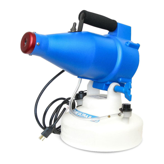
Summary of Contents for Dyna-Fog CYCLONE ULTRA 2734
- Page 1 ® DYNA-FOG CYCLONE ULTRA Ultra-Low Volume Sprayer MODEL 2734 & 2736 OPERATION AND MAINTENANCE MANUAL P a g e...
-
Page 2: Table Of Contents
INDEX Page No SAFETY PRECAUTIONS ........SPECIFICATIONS . -
Page 3: Safety Precautions
SAFETY PRECAUTIONS WARNING READ UNDERSTAND THESE SAFETY PRECAUTIONS BEFORE OPERATING MACHINE. FAILURE PROPERLY FOLLOW THESE PRECAUTIONS MAY LEAD TO A FIRE, EXPOSION OR ELECTRIC SHOCK HAZARD. ELECTRIC POWER. This machine uses electrical power at common commercially available voltages. When directly contacted, such voltages are hazardous to human life. - Page 4 higher or “no” flash point formulation can ignite if the proper conditions exist. These conditions are basically two: 1. A sufficiently volume of liquid in the form of fine particles suspended in the air; and 2. A sufficiently high-energy source of ignition. AEROSOL CONCENTRATION.
- Page 5 Ensure that formulation is applied only in strict compliance with the formulation label as well as local State and Federal regulations. DO NOT Do not Spray flammable liquids near open flame or other source of ignition. Do not Use a machine that is broken or damaged in any way. Do not Alter the machine by adding or removing parts.
-
Page 6: Specifications
SPECIFICATIONS The Cyclone™ Ultra machine is an electric “Cold Fog” ULV that utilizes a rugged anodized aluminum nozzle and a high performance blower. This device is intended for applications of both Oil Based (following necessary precautions) and Water Based chemical treatments. The body and tank are made of high-density chemical resistant polyethylene. -
Page 7: Principles Of Operation
PRINCIPLES OF OPERATION The machine consists of a motor/blower assembly, blower housing, a nozzle, formulation tank, tank neck filter, metering valve, check valve and shutoff valve (solenoid or manual, depending of the model). The various components are identified in the fluid systems diagram and major components diagram. The blower is a two-stage centrifugal compressor driven by a universal motor operating at a speed of 20,000 rpm. -
Page 8: Fluids System Diagram
FLUID SYSTEM DIAGRAM Cyclone™ Ultra P a g e... -
Page 9: Major Components Diagram
MAJOR COMPONENTS DIAGRAM Cyclone™ Ultra P a g e... -
Page 10: General Dimensions
GENERAL DIMENSIONS 10 | P a g e... -
Page 11: Flow Rate
CYCLONE™ FLOW RATE AND DROPLET SIZE (VOLUME MEDIAN DIAMETER) Valve 32 Seconds Droplet Size 40 Seconds Droplet 50 Seconds Droplet Size Positionin Formulatio Microns Formulation Size Formulatio Microns Microns LOW (*) 40 ML/MIN 8 VMD 37 ML/MIN 15 VMD ML/MIN 20 VMD 1.4 OZ/MIN 0.4 OZ/MIN... -
Page 12: Maintenance
MAINTENANCE 1. Periodically clean the formulation tank using a hot water/detergent solution. Fully open the machine valve and operate the machine for 3 to 5 minutes, flushing the solution through the valve, lines and nozzle. 2. Examine the electrical cord for evidence of damage and replace any damaged cord immediately. -
Page 13: Electrical Schematic
ELECTRICAL SCHEMATICS 13 | P a g e... -
Page 14: Rotary Fan Replacement
CAUTION: The Blower of your machine rotates at a high speed (approximately 20,000 RPM). The replacement of the Rotary Fan, if required, should be performed by a certified Dyna-Fog representative. If the machine has been working in a closed room, the intake air filter gets saturated, and liquid (chemical) is introduced to the blower. -
Page 15: Spare Parts For The Motor
4) Add the new fans positioning them as shown in below diagram, place the big washer with the smooth outside edge against the fan material, tighten out the nut to a torque of 20 to 25 Lb-Inch, and reinstall the end shell. A thread lock product like Loctite ref. 222 (purple) is recommended prior to reinstalling the nut onto the shaft thread. -
Page 16: Exploded Diagram
CYCLONE™ ULTRA EXPLODED DIAGRAM 16 | P a g e... -
Page 17: Exploded Diagram Parts List
CYCLONE™ ULTRA EXPLODED PARTS LIST DESCRIPTION ITEM 62130-10 TANK, 1 GAL 62135-2 CAP AY, TANK BLK 62131-2 CLEVIS, BLOWER 45933-1 STRAIN CONNECTOR 62031-2 POWER CORD AY, 120 AY 62313 NOZZLE ASSEMBLY CLAMP 80296-11 62343-1 EYELET, BRASS 62163 SCREW, 8-32 X 3/8, TAP 62325 INDICATOR PLATE 62316... -
Page 18: Parts List, Metering Valve Assembly
VALVE ASSEMBLY, BRASS (P/N: 62195) ITEM QTY. PART NUMBER DESCRIPTION 32692-1 NUT, PACKING, BRASS 32690 WASHER, PACKING 32691 WASHER, BRASS 62319-1 STEM, VALVE 62180 VALVE BODY/BARB AY. 10100-110 O-RING 62227-1 TUBE, BLUE, 3/16 ID. X 5.16 OD. 80408 FILTER, LONG TAPER, 130 MICRONS VALVE ASSEMBLY, SPARE PARTS KIT (P/N: 62185) -
Page 19: Noise Level Comparison
NOISE LEVEL COMPARISON CHART The Cyclone Ultra hand held electric aerosol applicator is a relatively quite machine, as shown in above comparison. 19 | P a g e... - Page 20 Rev. 11-4-2013 REV. 10-09 20 | P a g e...
Need help?
Do you have a question about the CYCLONE ULTRA 2734 and is the answer not in the manual?
Questions and answers