
Related Manuals for General Instrument DCT 1000

Summary of Contents for General Instrument DCT 1000
- Page 1 DCT 1000 Cable Terminal Installation Manual POWER GUIDE CURSOR INFO MENU SELECT BYPASS CHANNEL...
- Page 2 General Instrument. General Instrument reserves the right to revise this publication and to make changes in content from time to time without obligation on the part of General Instrument to provide notification of such revision or change. General Instrument provides this guide without warranty of any kind, either implied or expressed, including, but not limited, to the implied warranties of merchantability and fitness for a particular purpose.
-
Page 3: Table Of Contents
Remote Controls ......................XRC 100 Remote Control ..................Installing Batteries in Remote Control ..............Section 3 Installation Before You Begin ......................Installing the DCT 1000 ....................General Configuration Instructions ................Standard Wiring Cabling Diagrams ................A/B Switch-out Cabling Diagrams ................ - Page 4 Timers ........................Help ........................Appendix A Specifications Appendix B Diagnostics Accessing Diagnostics ....................Summary of Diagnostic Modes ................... d 01: DCT 1000 General Status ................d 02: Out-Of-Band Receiver Status ................ Carrier Lock ...................... Packet/Frame Sync ................... Data Activity ......................
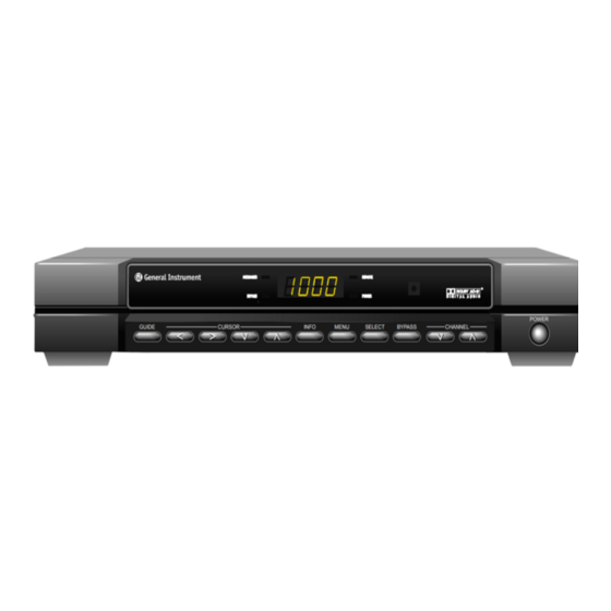
- Page 5 B-20 d 14: Memory Status ....................B-21 Figures Figure 1-1 Front view of the DCT 1000 cable terminal ..........Figure 1-2 Rear view of the DCT 1000 cable terminal ..........Figure 2-1 DCT 1000 cable terminal front panel ............Figure 2-2 DCT 1000 cable terminal rear panel ............
- Page 6 Table of Contents Figure 4-6 Composite VCR Cabling ................Figure 4-7 Stereo system cabling ................. Figure 5-1 XRC 200 remote control ................Figure 5-2 Notice screen ....................Figure 5-3 Setup screen, with Cable Terminal selected ..........Figure 5-4 Cable terminal setup screen ................ Figure 5-5 Configuration screen ..................
-
Page 7: Section 1 Introduction
Section 1 Introduction The DCT 1000 is an analog/digital cable terminal designed to be configurable and upgradeable to meet the future needs of emerging technologies in the communications industry. The base unit supports numerous configurations. This manual provides instructions on installing the base... -
Page 8: Using This Manual
Provides instructions on how to install a DCT 1000 cable terminal in a subscriber location and perform operational tests. Section 4 Provides instructions on how to connect a VCR or stereo equipment to a DCT 1000 cable terminal in a subscriber location. Section 5... -
Page 9: Related Documentation
Related Documentation Separate instruction manuals are available for associated components. Although these may be of interest to you, they are not necessary to install or operate the basic DCT 1000 cable terminal. DCT 1000 User Guide, part number 437-011-400 XRC 100 Remote Control User Guide, part number 437-053-400... -
Page 10: Section 2 Overview
In this section you will find illustrations and tables showing the features of the front and rear panels of the DCT 1000 cable terminal. Before beginning the installation process, please take the time to familiarize yourself with the various controls and displays. - Page 11 Overview Connector Function Turns terminal on/off. Change channel up and down. Operates the A/B or RF bypass switch. Selects function options and pay-per-view (PPV) events, and tunes channels from the electronic program guide. Displays main menu. Displays current channel and program information. Move cursor in menu and program guide screens.
-
Page 12: Rear Panel Connectors
Overview Rear Panel Connectors The rear panel of the DCT 1000 cable terminal, displayed in Figure 2-2, contains a switched power outlet; connectors for video, audio, and RF cabling; data output connectors; IR blaster output connectors; and an ac power plug. If a pay-per-view (PPV) module is not installed in the cable terminal’s rear panel, protective plates will cover the opening in the rear panel reserved for... - Page 13 Overview Connector Function Standard 2-prong polarized plug to connect the cable terminal to a power source. Mini phone jacks for connecting an optional IR Blaster. The high power output is optional. Mini phone jacks for connecting data output from the terminal.
-
Page 14: Configuration Options
Overview Configuration Options The DCT 1000 platform supports a variety of configurations. These options allow your company to offer options tailored to the needs of individual subscribers. Figure 2-3 shows the various options available for the DCT 1000 platform. Figure 2-3... -
Page 15: Remote Controls
Remote Controls The basic DCT 1000 uses the XRC 100 remote control. If your system offers an optional electronic program guide, a different remote control may be required; refer to Section 5, TV Guide On Screen. The XRC 100 may require programming before use; refer to its user guide for programming instructions. -
Page 16: Xrc 100 Remote Control
Overview XRC 100 Remote Control Figure 2-4 illustrates the XRC 100. Figure 2-4 XRC 100 remote control Installing Batteries in Remote Control Before a remote control can be used, two AA (1.5 volt) alkaline batteries must be installed in it. Battery access is located on the back of the remote control. -
Page 17: Section 3 Installation
Make certain you have the correct connecting cables for the audio connectors. Determine if you are going to connect a VCR to the DCT 1000 cable terminal. If the subscriber location requires an A/B switch-in, an A/B switch-out, or a STARVUE II or STARFONE module, install these options before beginning cabling. -
Page 18: General Configuration Instructions
Installation General Configuration Instructions The DCT 1000 cable terminal is available in numerous configurations. The cabling for each configuration is illustrated in this section. Use these general installation instructions and the cabling illustrations to install the terminal in the subscriber location. - Page 19 Installation Figure 3-2 Standard wiring with a STARVUE II module Figure 3-3 Standard wiring with a STARFONE module DCT1000 Installation Manual...
-
Page 20: A/B Switch-Out Cabling Diagrams
Installation A/B Switch-out Cabling Diagrams Figure 3-4 illustrates a standard wiring configuration which includes an A/B switch-out. If the cable terminal has a PPV module, refer to the PPV diagrams (Figure 3-5 and Figure 3-6) to determine the correct cabling for the configuration. Figure 3-4 A/B switch-out without a PPV module DCT1000 Installation Manual... - Page 21 Installation Figure 3-5 A/B switch-out with a STARVUE II module Figure 3-6 A/B switch-out with a STARFONE module DCT1000 Installation Manual...
-
Page 22: A/B Switch-In Cabling Diagrams
Installation A/B Switch-in Cabling Diagrams The A/B switch-in is commonly used in dual-cable systems. Figure 3-7 illustrates a standard configuration that uses an A/B switch-in. Figure 3-7 A/B switch-in without a PPV module If the cable terminal is equipped with a PPV module, refer to the PPV diagrams (Figure 3-8, Figure 3-9, and Figure 3-10) to determine the correct wiring for the configuration. - Page 23 Installation Figure 3-8 A/B switch-in with a STARVUE II module and the return on cable A Figure 3-9 A/B switch-in with a STARVUE II module and the return on cable B DCT1000 Installation Manual...
-
Page 24: Operational Check
Installation Figure 3-10 A/B switch-in with a STARFONE module Operational Check The operational check tests the communication link between the remote control and the cable terminal. The procedures verify the terminal’s response to the remote control commands. You use the remote control to test a basic cable terminal. If the terminal does not operate properly, refer to the Troubleshooting section. -
Page 25: Troubleshooting
Installation Troubleshooting Occasionally a terminal may fail to operate as described. Follow these suggestions to correct problems: Press and release operation keys one at a time, firmly and deliberately. Aim the remote control directly at the cable terminal, not the TV or VCR. Be sure there are no obstructions between the remote control and the cable terminal. -
Page 26: Section 4 Adding A Vcr Or Stereo Component
Section 4 Adding a VCR or Stereo Component Depending on the options in the DCT 1000 and the equipment attached to the cable terminal, there are numerous methods to connect a VCR or stereo equipment. This section gives a few of the standard configurations. -
Page 27: Rf Bypass Switch Vcr Cabling Diagrams
Adding a VCR or Stereo Component RF Bypass Switch VCR Cabling Diagrams The configurations shown in Figure 4-2 and Figure 4-3 allow viewing an unscrambled analog channel directly on a TV while recording another channel through the terminal. Figure 4-2 RF Bypass switch with VCR DCT1000 Installation Manual... - Page 28 Adding a VCR or Stereo Component Figure 4-3 RF Bypass switch with VCR and STARVUE II module DCT1000 Installation Manual...
-
Page 29: A/B Switch-Out Vcr Cabling Diagram
Adding a VCR or Stereo Component A/B Switch-Out VCR Cabling Diagram The arrangement shown in Figure 4-4 allows both the TV and the VCR to receive cable-ready channels directly. Figure 4-4 A/B switch-out with VCR DCT1000 Installation Manual... -
Page 30: A/B Switch-In Vcr Cabling Diagram
Adding a VCR or Stereo Component A/B Switch-In VCR Cabling Diagram The cabling configuration illustrated in Figure 4-5 allows for one of the following: In the primary configuration (shown in solid lines), mode A tunes the TV to the VCR output channel and the VCR can record a scrambled or non-scrambled channel. -
Page 31: Composite (Baseband) Vcr Cabling Diagram
Adding a VCR or Stereo Component Composite (Baseband) VCR Cabling Diagram The baseband audio and video outputs of the cable terminal are available to connect to a VCR as displayed in Figure 4-6. The VCR can be cabled to either a standard TV by an F-type connector or to a TV/monitor with audio and video connectors. -
Page 32: Stereo System Cabling Diagram
Adding a VCR or Stereo Component Stereo System Cabling Diagram The configuration shown in Figure 4-7 uses the audio loop-through inputs on the DCT 1000. In this configuration a subscriber’s CD player and VCR can be played through a stereo receiver. -
Page 33: Section 5 Tv Guide On Screen
Section 5 TV Guide On Screen The DCT 1000 supports the TV Guide On Screen electronic program guide. If your cable company offers this service, this section will help you get TV Guide On Screen up and running for your subscriber. It also describes a few basic operations to help you introduce the subscriber to TV Guide On Screen. -
Page 34: Xrc 200 Remote Control
TV Guide On Screen XRC 200 Remote Control Figure 5-1 illustrates the XRC 200 remote control. Figure 5-1 XRC 200 remote control Installing Batteries in Remote Control Before a remote control can be used, two AA (1.5 volt) alkaline batteries must be installed in it. Battery access is located on the back of the remote control. -
Page 35: Quick Tips For The Program Guide
Help, pressing the same key will exit that screen or mode. Setting Up the Program Guide Once the DCT 1000 cable terminal has been successfully installed as described in Sections 3, Installation, and Section 4, Adding a VCR or Stereo Components, it will take approximately 5 to 15 minutes for TV Guide On Screen to become functional with listings information for the current hour. -
Page 36: Confirm Proper Installation
TV Guide On Screen Confirm Proper Installation Once TV Guide On Screen becomes available, follow these easy steps to confirm that it is functioning properly: Press MENU Press the Down Arrow to open the Viewer Services section of the menu. Press the Right Arrow to highlight Setup. -
Page 37: Configure Tv Guide On Screen
TV Guide On Screen Highlight Review, then press . The configuration screen shown in Figure 5-5 will appear. Review the meaning of the various parts of the screen with the subscriber. Figure 5-5 Configuration screen After confirming that TV Guide On Screen is functioning properly, press twice to MENU return to television viewing. - Page 38 TV Guide On Screen Press . The setup screen shown in Figure 5-6 will appear. Figure 5-6 Setup screen, with TV Guide On Screen selected Highlight TV Guide On Screen, then press . The screen shown in Figure 5-7 will appear. Review the meaning of the various parts of the screen with the subscriber.
-
Page 39: Getting Started With The Program Guide
TV Guide On Screen Getting Started with the Program Guide Here are a few things to point out to the subscriber about using TV Guide On Screen. Remind the subscriber to refer to the TV Guide On Screen Reference Guide. Flip The flip bar will appear each time the channel is changed and will disappear after 5 seconds. -
Page 40: Lockout
TV Guide On Screen After reading the message, the subscriber can highlight either Keep or Delete, then press Lockout The subscriber may restrict viewing of certain programs based on its MPAA rating, the channel it’s on, or even its title. To set a lock: Highlight Lockout from within the Viewer Services section of the Main Menu, then press The subscriber may also press while watching a program or while highlighting a program... -
Page 41: Appendix A Specifications
Appendix A Specifications Input Frequency 54 to 860 MHz (excluding data carrier frequency) HRC/IRC Frequency Assignments Downloadable Number of Channels 136 carriers per cable, 1 or 2 cables Analog 1 channel per carrier Digital More than 1 channel per carrier, content dependent Dual A/B Cable Switching Optional A/B switch (field upgradeable) Input Analog Video Level... - Page 42 Specifications Differential Phase 10 degrees (maximum) Scrambling Method Gated sync suppression or dynamic gated sync suppression, video inversion, audio privacy, Hamlin compatibility On Screen Display Screen Size 352 x 480 pixels Message/Barker Capacity Up to 40 pages (configuration dependent) Channel Descriptors 4 character, maximum Mechanical Security Standard: security screws;...
-
Page 43: Appendix B Diagnostics
Appendix B Diagnostics This section describes the diagnostics provided for the DCT 1000 cable terminal. The diagnostics are designed to confirm proper installation of the DCT 1000. They include provisions to identify the terminal on the network and to verify communications with the headend. -
Page 44: Summary Of Diagnostic Modes
APPLICATION EXP. MODULE MEMORY CONFIGURATION Summary of Diagnostic Modes The following table summarizes the diagnostic modes: Diagnostic d 01 General status of the DCT 1000 d 02 QSPK out-of-band receiver status d 03 64 QAM in-band receiver status/analog channel status d 04... -
Page 45: D 01: Dct 1000 General Status
Application expansion module d 14 Memory configuration d 01: DCT 1000 General Status This diagnostic indicates the general status of the terminal. The LED display (Figure B-2) alternates between the error code and the purchase count. The OSD display (Figure B-3)) shows the error code, a short description of the error, and the purchase count. -
Page 46: D 02: Out-Of-Band Receiver Status
Diagnostics Currently, the following error codes are supported: Error Code On Screen Display Cause Remedy E 00 NO ERROR Indicates normal condition Not applicable. after initialization. E 01 to E 06 Not currently defined. Not applicable. E 07 FAULTY ROM Faulty ROM. -
Page 47: Carrier Lock
Diagnostics Figure B-5 Out-of-band status OSD display data OUT-OF-BAND DIAGNOSTIC DATA EMM DATA CARRIER LOCK PACKET/FRAME SYNC Figure B-6 LED indication of no data received Carrier Lock Carrier lock indicates whether or not the out-of-band receiver is locked to the carrier. LED and OSD indications are as follows: Status Carrier locked... -
Page 48: D 03: In-Band Receiver Status
Data received d 03: In-Band Receiver Status The DCT 1000 displays the digital diagnostics. If there is no digital carrier, these diagnostics indicate the carrier is not locked. The LED and OSD displays are shown in Figure B-7 and Figure B-8. -
Page 49: Carrier Lock
Diagnostics Figure B-8 In-band receiver digital status OSD display data IN-BAND DIAGNOSTIC: DIGITAL DATA EMM DATA CARRIER LOCK REED/SOLOMON PACKET/FRAME SYNC Carrier Lock This diagnostic indicates whether or not the in-band receiver is locked to the carrier. The LED and OSD indications are as follows: Status Carrier locked Carrier unlocked... -
Page 50: Adaptive Equalizer Stress
Diagnostics Adaptive Equalizer Stress The status of the adaptive equalizer (AE) is indicated as follows: Status AE is near its operating limit AE is operating within design parameters Data Activity Indicates that a message was received. The indicator will be cleared when this diagnostic mode is entered and three seconds after the last message is received. -
Page 51: D 05: Qam Receiver Long-Term Error Rate
Diagnostics Figure B-10 Receiver short-term error rate OSD display data IN-BAND RECEIVER STATUS SHORT-TERM ERROR COUNT AE COEFFICIENTS (1 of 2) d 05: QAM Receiver Long-Term Error Rate This diagnostic displays the latest Reed-Solomon error rate over an extended period of time, typically 24 hours. -
Page 52: D 06: Unit Address
B-10 Diagnostics Figure B-12 Receiver long-term error rate OSD display data IN-BAND RECEIVER STATUS LONG-TERM ERROR COUNT AE COEFFICIENTS (2 of 2) d 06: Unit Address This diagnostic displays the terminal’s 16-digit (40-bit) unit address, which is written at manufacturing time. It shows in five parts on the four-section LED display. The address display stays on each section for five seconds. -
Page 53: D 07: Unit Serial Number
Diagnostics B-11 Figure B-13 Unit address LED display Figure B-14 Unit address OSD display data Unit Address Unit Address 123-45678-90123-456 Network Address 123-45678-90123-456 TVPC 123-45678-90123-456 Multicast 16 Address 255.255 255.255 255.255 255.255 d 07: Unit Serial Number This diagnostic displays the terminal’s unit serial number which is assigned at manufacture. It is shown in parts on the four LED sections. -
Page 54: D 08: Dena Firmware Version
The serial number is displayed directly on the OSD screen, as illustrated in Figure B-16. Figure B-16 Unit serial number OSD display data DCT 1000 SERIAL NUMBER D53G9176543267 d 08: Dena Firmware Version This diagnostic shows the Dena firmware version. The LED display, as illustrated in Figure B-17, alternates between showing the firmware version number and the characters dENA. -
Page 55: D 09: Current-Channel Status
Diagnostics B-13 The OSD screen, as illustrated in Figure B-18, displays the revision number and the build date. Figure B-18 Dena firmware version OSD display data DENA FIRMWARE VERSION 12.34 12/31/94 d 09: Current-Channel Status This diagnostic gives the instantaneous status of the last tuned channel on the in-band tuner. It indicates if the current program is analog clear, analog with tagging data, barker channel, or a digital channel. -
Page 56: Decryptor Status Modes
B-14 Diagnostics The OSD screen is shown in Figure B-20. Figure B-20 Decryptor status OSD display data CURRENT-CHANNEL STATUS STATUS CLEAR PURCHASABLE TSODA VERSION CAMEL VERSION Decryptor Status Modes The LED and OSD indications of the decryptor status modes are as follows: Meaning CLEAR Clear analog channel... -
Page 57: D 10: Renewable Security System
Diagnostics B-15 d 10: Renewable Security System The renewable security system returns the current status of the TvPC. This includes an indication of whether or not the TvPC is required, and the mode, status and version. The LED display is shown in Figure B-21. Figure B-21 Renewable security status LED display The OSD screen is shown in Figure B-22. -
Page 58: Current Mode
B-16 Diagnostics Current Mode The current mode is indicated as follows: Status STAND ALONE Stand alone SUPPORT Support NOT MATED Not mated TvPC Status TvPC status is indicated as follows: Status TvPC communication problem TvPC required Validator does not match between GK and TvPC Invalid unit key number Old TvPC unit address TvPC not mated... -
Page 59: Starvue Ii Diagnostics
Diagnostics B-17 STARVUE II Diagnostics This diagnostic shows the status and operating parameters for the STARVUE II module. The LED and OSD displays are shown in Figure B-23 and Figure B-24. Transmit frequency is shown in megahertz. The display range is 8.0 to 15.0 MHz Level shows the hex value of the power level of the STARVUE II transmitter. -
Page 60: Starfone Diagnostics
B-18 Diagnostics IPPV status is indicated as shown in the following table. Note that UNSENT is followed by the number of unsent transactions. Status ENABLED IPPV enabled flashing UNSEEN– ## This terminal contains unsent IPPV transactions DISABLED IPPV disabled STARFONE Diagnostics This diagnostic shows the status and operating parameters for the STARFONE module. - Page 61 Diagnostics B-19 The status of the transmitter is shown as follows: 1st Digit 2nd Digit Meaning On Hook (* = hang-up code) – Test for line available – Dialing – Waiting for answer Communicating, receiving Communicating, transmitting – Communicating, Idle Waiting for retry (* = hang-up code) The hang-up code is shown as follows: Mode...
-
Page 62: D 12: Application Code Modules
B-20 Diagnostics The third digit baud rate is shown as follows: Mode 300 Baud The fourth digit telephone parameters are shown as follows: Mode — NOT SET Telephone parameters not set P (flashing) NOT VALID Telephone parameters not valid P (solid) Telephone parameters OK d 12: Application Code Modules This diagnostic displays the currently downloaded code modules. -
Page 63: D 14: Memory Status
Diagnostics B-21 d 14: Memory Status The memory free value is the sum of all free memory. This free memory is not necessarily in one block. The OSD display is shown in Figure B-29. There is no LED display for this diagnostic. - Page 64 General Instrument Corporation GI Communications Division Printed in U.S.A. 405957-001-99, 7/96...
Need help?
Do you have a question about the DCT 1000 and is the answer not in the manual?
Questions and answers