Advertisement
Quick Links
FX3GC PLC User Manual
Thank you for choosing Coolmay FX3GC series PLC. This manual mainly explains the features, general
specifications and wiring methods of FX3GC series. More detail programming information please refer to
"Coolmay CX3G&FX3GC PLC Programming Manual".
The FX3GC series is a compact PLC with the following features:
1. Highly integrated. Digital at most 16DI/16DO (digital type can be customized transistor, relay or mixed).
Analog at most 8AI 6AO, input can be customized temperature, current, voltage or mixed (support-5~5V/
-10V~10V), output can be customized current and voltage.
2. Comes with two PLC programming ports: MiniB USB port (faster download speed) and RS232 port.
3. Support multi-channel high-speed counting and high-speed pulse functions. High-speed counting
normally single-phase 6 60KHz, or AB (Z) phase 2 60KHz + AB phase 1 10KHz. High-speed pulse is normally
8 channels, Y0-Y3 is 100KHz, Y4-Y7 is 10KHz. Acceleration and deceleration are independent; the total of
high-speed counting + high-speed pulse cannot exceed 480KHz.
4. Support special encryption. Setting the password to 12345678 can completely prohibit reading programs.
[Note: Only 8-bit password encryption is supported]
5. Convenient wiring, using 3.5mm pitch pluggable terminals.
Production Information
-
-
-
-
-
◆
FX3GC
16
M
RT
8AD
4DA
V
A0
1C1
Naming rules
1
2
3
4
5
6
7
8
1. Series:
FX3GC: FX3GC series PLC
2. I/O points:
16: 8DI 8DO 30: 16DI 14DO 32: 16DI 16DO
3. Module
M: Main Module
4. DO type:
R: Relay; T: Transistor; RT: Relay and transistor mixed
5. AI
0-8 channels are optional
6. AO
0-6 channels are optional
7. AI type
PT: PT100
PT1000: PT1000
NTC: Thermistor (10K/50K/100K)
V: 0 -10V
V5: 0-5V
V_: -10~10V
V5_: -5~5V
A0: 0-20mA
A4: 4-20mA
E: E type thermocouple (K type/T type/S type/J type can be customized, supporting negative temperature)
8. AO type
V: 0-10V
V5: 0-5V
A0: 0-20mA
A4: 4-20mA
V_: -10~10V
[Note: Optional negative voltage occupies two DA channels]
9. C1 means single-phase high-speed counting, C2 means AB phase counting, and C3 means ABZ phase counting.
Normally single phase 6 channels 60KHZ, or AB (Z) phase 2 channels 60KHz + AB phase 1 channel 10KHz.
10. P0 means 10KHz high-speed pulse, P means 100KHz high-speed pulse. High-speed pulse normally
8 channels, Y0-Y3 is 100KHz, Y4-Y7 is 10KHz; acceleration and deceleration are independent; high-speed
counting + high-speed pulse total cannot exceed 480KHz.
11. COM port.
Refer to【Table 1: Basic parameters】
◆
Basic parameters
Digital
Com ports
Analog
High-speed counting
points
(optional)
(optional)
Model
Single
MAX
MAX
CAN
DI DO
AB phase
RS485
phase
AI
AO
(2.0A/B)
6
4
2
1
4
FX
3G -16M
C
8
8
8
1
1
Normally
Normally
AB phase
single
2 channel
1
None
8
6
phase
60KHz+
6 channels
60KHz
1 channel
FX
3G -30M
C
16 14
1
None
10KHz
None
None
FX
3G -32M
C
16 16
MT: Y0-Y7 is MOS tube output, Y10-Y17 is transistor output; MR: relay output; MRT: mixed output.
Optional according to customer requirements.
Electrical parameters
Input voltage
DC 24V
Digital input index
Isolation mode
Photoelectric coupling
Input resistance
High-speed input 3.3KΩ
Electric current of high-speed input
Input ON
is higher than 5.8mA/24V
Electric current of high-speed input
Input OFF
is higer than 4.5mA/19V
(Continued from the table above)
Filter function
High-speed counting
Input level
Max current
Load voltage
Circuit insulation
On response time
Mechanical life (no load)
Electrical life (rated load)
Output level
Max current
-
-
1P
485/CAN
9
10
11
Load voltage
Circuit insulation
Isolation voltage
(power supply-external terminal)
On response time
High-speed frequency output
Output level
V5_: -5~5V
Input signal
Response time
Analog input quantity
Accurary
Table 1: Basic parameters
High-speed
Size
pulse
Output signal
Analog output quantity
ABZ
Dimensions
Output
(mm)
phase
Accurary
Programming port
Normally
8 channels,
Normally
COM port
Y0-Y3 is 100KHz,
ABZ phase
Y4-Y7 is 10KHz;
90*65*32
2 channel
HSC + HSP
60KHz
can not
Operating temperature
exceed
480KHz.
Relative humidity
Storage temperature
Vibration frequency
Mechanical Design Reference
Table 2 Electrical parameters
Installation size
◆
Common input 4.3Ω
Electric current of common input
is Higherthan 9.9mA/24V
Electric current of common input
is Higher than 4mA/17V
With filter function, the filter time can be set among 0-60ms,
defaulted as 10ms
Normally single phase 6 channels 60KHz or AB (Z) phase
2 channels 60KHz + AB phase 1 channel 10KHz
Passive NPN, common terminal isolation, S/S connected to 24V+
Digital relay output index
2A/point, 5A/8point COM
Below DC30V/ Below AC220V
Relay mechanical insulation
About 10ms
10 million times
300,000 times
Normally open dry contact output, COM can be connected to positive or negative
Digital transistor output index
MOS tube: 2A/point, 4A/4point COM, 5A/12point COM;
MT: 0.5A/point, 0.8A/4point COM, 1.6A/12point COM
DC24V
Optocoupler insulation
1500VAC
High-speed output: 10μs, other 0.5ms
Normally 8 channels, Y0-Y3 is 100KHz, Y4-Y7 is 10KHz
High-speed counting + high-speed pulse total does not exceed 480KHz
Low level NPN, COM connected to negative
Analog input index
PT100/PT1000/thermocouple/NTC/0-10V/0-5V/-10~10V/-5~5V/0-20mA/4-20mA
other customization
1 scan cycle
0-8 Channel
12 bits
Analog output index
0-5V/0-10V/-10~10V/-5~5V/0-20mA/4-20mA/other customization
0-6 Channel
12 bits
External interface
Comes with 2 programming ports: Mini B USB port
(faster download speed) and Rs232
Refer to【Table 1: Basic parameters】
Environment
0°C~50°C
5%~95%RH
-20°C~70°C
10-57Hz, amplitude 0.035mm; 57Hz-150Hz, acceleration speed 4.9m/s²
(10 times each on X, Y, Z, total 80 minutes each)
90
65
32
Dimensions 90*65*32(mm)
Installation size: DIN rail (35mm)
Diagram 1 Installation dimension drawing
Electrical Design Reference
◆
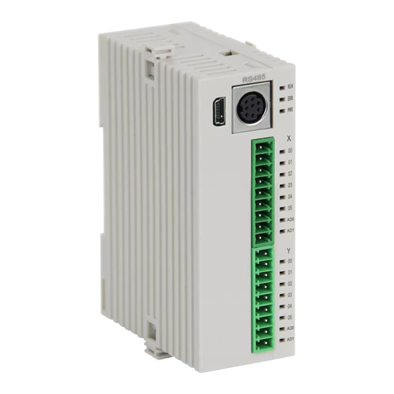
Product structure
9
6
8
13
4
4
12
10
12
5
5
3
3
11
7
Diagram
2 Product structure
1. 35mm rail installation
2. Terminal block for power input signal
3. Digital output terminal block
4. Digital input display LED
5. Digital output display LED
6. PWR: Indicates the power-on state
RUN: The light is on when the PLC is running
7. Optional RS485
8. PLC programming port
ERR: The indicator light flashes when the program
9. RUN/STOP PLC operation switch
10. Analog input (optional 485)
error occurs (the indicator light is on when the
11. Analog output (optional CAN)
12. Digital input terminal block
CPU error occurs)
13. Mini USB programming port (faster download speed)
◆
Hardware interface
RUN
RUN
ERR
ERR
PWR
PWR
S/S
S/S
S/S
GND
00
A0
00
10
01
A1
01
11
02
A2
02
12
03
A3
03
13
04
04
14
A4
05
A5
05
15
06
A1
A6
06
16
07
B1
A7
07
17
Y
Y
GND
Y
00
D0
00
10
01
D1
01
11
02
D2
02
12
03
D3
03
13
04
H
D4
04
14
05
D5
05
15
06
L
A
06
A
07
B
07
B
Diagram 3 FX3GC-16MR/MT/MRT
Diagram 4 FX3GC-16M
Diagram 5 FX3GC-30MR/
communication port/analog expansion
Note: S/S is the common terminal of digital input, which is connected to the positive pole of 24V;
is the public terminal of switch output;
GND is the common terminal of analog input/analog output
Y
Terminal wiring specifications: 22-14AWG wire. The terminals of this series of models are all pluggable terminals.
For special model interfaces, please refer to the product silk screen.
RS232 programming port pin definition
① ②
Pin No.
Description
Signal
③ ④ ⑤
⑥ ⑦
4
RXD
Receive
5
TXD
Send
Diagram 7 RS232
GND
8
Ground
programming port
Comes with two programming ports:
Mini B-type USB port (faster download speed) and RS232 (8-pin mouse female socket)
16M can expand at most 2 RS485, 1 CAN port (2.0A/B), 6 inputs and 4 outputs analog
Or 1 RS485, 1 CAN port (2.0A/B), 8 inputs and 4 outputs simulation
Or 1 RS485, 8 inputs and 6 outputs analog
Or 2 RS485, 1 CAN port (2.0A/B)
Communication port description
◆
Serial port 1: RS422 (PLC programming port): Supports Mitsubishi programming port protocol,
which can be used to download PLC programs or communicate with devices that support
Mitsubishi programming port protocol.
◆
Serial port 2: RS485 (AB port): Support Mitsubishi programming port protocol, Mitsubishi BD protocol,
RS protocol and Modbus RTU protocol.
※ Support RS, RS2, WR3A, RD3A, ADPRW instructions.
◆
Serial port 3: RS485 (A1B1 port): Supports Mitsubishi programming port protocol, RS2 protocol and
Modbus RTU protocol.
※Support RS2, WR3A, RD3A, ADPRW instructions.
◆
CAN port: supports RS2 protocol and Modbus RTU protocol.
※Support RS2, WR3A, RD3A, ADPRW instructions.
※
Note: For detailed settings, please refer to "Coolmay CX3G&FX3GC Series PLC Programming Manual"
2
1
RUN
RUN
ERR
ERR
PWR
PWR
S/S
S/S
S/S
00
10
00
01
11
01
02
12
02
03
13
03
04
14
04
05
15
05
06
16
06
07
17
07
Y
Y
Y
00
10
00
01
11
01
02
12
02
03
13
03
04
14
04
05
15
05
06
16
06
07
17
07
Diagram 6 FX3GC-32MR/
MT/MRT
MT/MRT
485+ A1
485- B1
H
L
⑧
485+ A
485- B
Diagram 8 Optional
communication port
Advertisement

Subscribe to Our Youtube Channel
Related Manuals for Coolmay FX3GC Series


Summary of Contents for Coolmay FX3GC Series
- Page 1 Passive NPN, common terminal isolation, S/S connected to 24V+ Input level Thank you for choosing Coolmay FX3GC series PLC. This manual mainly explains the features, general Digital relay output index specifications and wiring methods of FX3GC series. More detail programming information please refer to "Coolmay CX3G&FX3GC PLC Programming Manual".
- Page 2 2. When the analog quantity is disturbed, 104 ceramic capacitors can be added for filtering and correct and effective grounding. Load “FX3GC PLC User Manual" and "Coolmay PLC instruction programming manual" ※ Note: For more details, please refer to Coolmay official website "PLC anti-interference processing method” Y017 Load Y010 Programming Reference FX3GC PLC User Manual ◆...
Need help?
Do you have a question about the FX3GC Series and is the answer not in the manual?
Questions and answers