Table of Contents
Advertisement
Advertisement
Table of Contents

Subscribe to Our Youtube Channel
Related Manuals for Bruker SmartCooler BCU I

Summary of Contents for Bruker SmartCooler BCU I
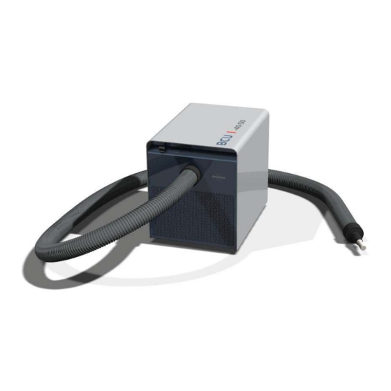
- Page 1 SmartCooler BCU I ● User Manual Version 003 Innovation with Integrity...
- Page 2 © April 06, 2018 Bruker Corporation Document Number: Z4D12628B P/N: Z33119 For further technical assistance for this product, please do not hesitate to contact your nearest BRUKER dealer or contact us directly at: Bruker Corporation Industriestrasse 26 CH-8117 Fällanden Germany Phone: + 49 721 5161 6155 E-mail: nmr-support@bruker.com...
-
Page 3: Table Of Contents
2.4.2 Dangers from Electric Power .................... 9 2.4.3 Dangers from Magnetic Fields .................. 10 Signage.......................... 11 Spare Parts / Accessories.................... 11 Introduction............................ 13 SmartCooler BCU I ...................... 13 Technical Data ........................ 14 3.2.1 General Information ...................... 15 Installation and Initial Commissioning................ 17 Limitation of Liability...................... 17 Copyright........................... 17 Warranty Terms ........................ 17 Customer Service ...................... 17... - Page 4 Contents Maintenance Work ...................... 38 Troubleshooting .......................... 39 Problems & Solutions...................... 40 10 Replacement of Parts........................ 43 10.1 Returning the Unit for Repair .................... 43 11 Dismantling and Disposal........................ 45 11.1 Dismantling ........................ 45 11.2 Disposal Europe........................ 45 11.3 Disposal USA and Other Countries .................. 46 12 Contact .............................. 47 Z33119_2_003...
-
Page 5: About
About Policy Statement It is Bruker’s policy to improve products as new techniques and components become available. Bruker reserves the right to change specifications at any time. Every effort has been made to avoid errors in text and Figure presentation in this publication. - Page 6 About NOTICE NOTICE indicates a property damage message. This is the consequence of not following the notice. 1. This is a safety condition. u This is a safety instruction. SAFETY INSTRUCTIONS SAFETY INSTRUCTIONS are used for control flow and shutdowns in the event of an error or emergency.
-
Page 7: Safety
Safety Safety Intended Use The device has been designed and constructed solely for the intended use described here. The SmartCooler BCU I is the successor model of the BCU05. The lowest temperature of the cooled VT gas is with a BCU I below -40°C up to 50 Nl/min. The SmartCooler BCU I produces the cooling energy via one compressor refrigerator with electrical power. -
Page 8: Personnel Requirements
• The system owner must ensure that all (electrical, mechanical, etc.) safety devices are regularly checked to ensure full safety functionality and completeness. Personnel Requirements Only trained Bruker personnel are allowed to install, mount, retrofit, repair, adjust and dismantle the unit! Basic Dangers The following section specifies residual risks which may result from using the device and have been established by means of a risk assessment. -
Page 9: General Workplace Dangers
Safety 2.4.1 General Workplace Dangers WARNING Danger to life from nonfunctional or insufficient safety devices! If safety devices are not functioning or are disabled, there is a danger of serious injury or death. u Check that all safety devices are fully functional and correctly installed before starting work. -
Page 10: Dangers From Magnetic Fields
Safety 2.4.3 Dangers from Magnetic Fields WARNING Risk to life due to high magnetic fields A magnetic field of more than 0.5 mT (5 Gauss) is life-threatening for people with pacemakers or active metal implants. Exposure to more than 8 T can cause damage to health. -
Page 11: Signage
Danger Spot Warning indicating a danger spot in work rooms. The warning label may be ordered using Bruker Part Number 67470. Spare Parts / Accessories Loss of Guarantee The use of non-approved spare parts will invalidate the manufacturer‘s guarantee. - Page 12 Safety Z33119_2_003...
-
Page 13: Introduction
Z29715 (500/52LL); M10910 (900 MHz/54 US2); 29563 (750/52 Magnex); O019 (500/52LL), O048 (400/54 Oxford) • 8 m: 1000 US SB For BRUKER magnets the following rules are valid to determine the minimal transfer line length of a BCU I: • Ascend (all frequencies) and all other magnets ≤ 700 MHz: Place the BCU I outside the 0.5 T (5 G) line and not less than 1m from the axis of the magnet. -
Page 14: Technical Data
Introduction Figure 3.2: Schema with BCU Technical Data Figure 3.3: View of the BCU of the front and the back. Rotary switch Rating plate LEDs (2x) Variable temperature (VT) gas IN Ø=8mm (max. 6bar) Transfer line – VT gas OUT Main switch Air inlet grid Fuse (2 x 5 x 20mm 10AT) Air outlet grid... -
Page 15: General Information
≤ -50 °C @ 1 bar Flow rate 0…3000 Nl/h Operating Environment Data Value Ambient operating temperature Min 17 °C, max 32 °C, 17…25 °C, specifications range fulfilled For the appropriate temperature see also the Bruker site planning guides on the BASH CD (Bruker Advanced Service Handbook). Z33119_2_003... - Page 16 Introduction Rating Plate The rating plate is located at the power input and includes the following information: • Manufacturer • PN: Part Number • Type • SN: Serial Number • Voltage • V: Variant • Frequency • ECL: Engineering Change Level •...
-
Page 17: Installation And Initial Commissioning
Installation, initial commissioning, retrofitting, repairs, adjustments or dismantling of the device must only be carried out by Bruker Service or personnel authorized by Bruker. Damage due to servicing that is not authorized by Bruker is not covered by your warranty. Limitation of Liability... - Page 18 Introduction Z33119_2_003...
-
Page 19: Transport, Packaging And Storage
Installation, initial commissioning, retrofitting, repairs, adjustments or dismantling of the device must only be carried out by Bruker Service or personnel authorized by Bruker. Damage due to servicing that is not authorized by Bruker is not covered by your warranty. Symbols on the Packaging The following symbols are affixed to the packaging material. -
Page 20: Inspection At Delivery
Transport, Packaging and Storage Inspection at Delivery Upon receipt, immediately inspect the delivery for completeness and transport damage. Figure 4.1: Shock sensor Therefore check the Tilt watches on both sides of the packaging. Proceed as follows in the event of externally apparent transport damage: •... -
Page 21: Storage
Transport, Packaging and Storage Storage Storage of the Packages Store the packages under the following conditions: • Do not store outdoors. • Store in dry and dust-free conditions. • Do not expose to aggressive media. • Protect against direct sunlight. •... -
Page 22: Unpacking Procedure
Transport, Packaging and Storage Unpacking Procedure Check the Tilt watches when the box is positioned in the lab. First open the black plastic belts. Then cut the tapes along the cardboard box edges and on the top. On top of the packed BCU I are the security hints and the packaging list provided. - Page 23 Transport, Packaging and Storage Take the transfer line carefully out. Lift together with a second person the BCU I (~30kg) out of the cardboard box. Remove the butterfly nuts on the bottom of the BCU I and keep them for later use. The BCU I can be placed according to the instructions in Preparation.
- Page 24 Transport, Packaging and Storage The white plastic cover has to be taken off, when the BCU I will be connected to the probe. When the transfer line is not connected cover the connector with the white plastic cover. Check each time that the O-ring at the front of the transfer line connector is clean before it is connected to the probe.
-
Page 25: Preparation
Preparation Preparation CAUTION Accident and material damage hazard due to flying objects When the operator pressurizes the transfer line before the protective cover is taken off, it can shoot away. u Remove the white protective cover of the transfer line before pressurizing the BCU with VT gas (max. - Page 26 Preparation Release and remove the transport safety lock, which are the two butterfly nuts at the bottom of the BCU I housing (1). Position the BCU I taking the magnetic fringe field into account. • For Ascend™ (all frequencies) and all other magnets ≤ 700MHz: Place the BCU I outside 0.5mT (5 G) and not less than 1m from the axis of the magnet.
- Page 27 Preparation Optional equipment: A MAS box (Z120576) is required with a BVT3x00 and MAS. A membrane dryer (1808577) is required in case the VT gas does not meet the dew point temperature specifications (General Information). See also 2 General Information [} 15] Z33119_2_003...
- Page 28 Preparation Z33119_2_003...
-
Page 29: Installation
≤ -50 °C @ 1bar according to the specifications. u For the BCU I Bruker recommends the dryer 1808577 (≤ 60nl/min). u Install the gas dryer upstream the B(S)VT. u For all tubing downstream the gas dryer use only hoses from TPS (low water permeability). - Page 30 Installation Z33119_2_003...
-
Page 31: Operation
Operation Operation WARNING Danger of injury from improper operation! Improper operation can result in serious injury and significant damage to property. u Carry out all operating steps in accordance with the specifications and instructions in this manual. u Before starting work, ensure that - All covers and safety devices are installed and functioning properly. -
Page 32: Status And Remote Led
Operation Status and Remote LED Status LED Information NO power Green flashing Cooling down / Warming up Green ON READY, stable temperature Red flashing WARNING, BCU I is overheating Red ON ERROR, see Troubleshooting for details BCU I is connected with BSVT Remote LED Information Manual Operation Mode or NO power... -
Page 33: Manual Operation Modes Bcu I
Operation Manual Operation Modes BCU I Rotary switch Operation Notes The BCU I is controlled by the BSVT (see Remote Operation Modes on BSVT [} 33] ) or BVT (see Remote Operation Modes on BVT [} 34] Flush / 0 * No cooling power This setting is used when VT gas at room temperature has to be fed to the NMR probe or the VT gas tubing of the BCU I has to be dried and purged. -
Page 34: Remote Operation Modes On Bvt
Operation Remote Operation Modes on BVT Rotary switch TopSpin EDTE Operation Notes Remote No cooling power This setting is used when VT gas at room temperature has to be fed to the NMR probe or the VT gas tubing of the BCU I has to be dried and purged. -
Page 35: Maintenance
Maintenance Maintenance Safety Electrical System WARNING Danger of injury from electrical shock! A life threatening shock may result when the housing is open during operation. u Only qualified personnel should open the housing. u Disconnect the device from the electrical power supply before opening the device. Use a voltmeter to verify that the device is not under power! u Be sure that the power supply cannot be reconnected without notice. - Page 36 Maintenance Moving Parts CAUTION Accident hazard from movement of mechanical parts! The fingers or hand may be pinched due to movement of mechanical parts. u Shut off the device before accessing it. Environmental protection Observe the following environmental protection instructions during maintenance work: •...
-
Page 37: Required Parts
Maintenance Required Parts The following spare parts can be ordered for the BCU I • Fan set 220-240V, 50Hz / 60Hz Z129903 • Fan set 100V / 50Hz or 100-115V / 60Hz Z129904 • Dust filter set BCU I Z150447 •... -
Page 38: Maintenance Work
Maintenance • O-ring 13.00X1.50 VITON green 1801892 Maintenance Work Figure 8.1: Replacing dust filter Housing cover Filter grid Hexagon socket screws Dust filter Fasteners of filter grid The BCU I has a dust filter (Z150447). For optimal performance and maximum lifetime of the BCU I the dust filter has to be cleaned or replaced every 6 months. -
Page 39: Troubleshooting
Troubleshooting Troubleshooting Please refer to the table on the following page. Z33119_2_003... -
Page 40: Problems & Solutions
Troubleshooting Problems & Solutions Problem Status LED Remote Cause Solution Low cooling Green irrelevant • BCU is in cool phase Wait 15 min power flashing (normal state) Low cooling Green irrelevant • Wrong Power Mode • Check / set chiller target power in edte to Power mode: power strong •... - Page 41 Troubleshooting Problem Status LED Remote Cause Solution BCU not visible irrelevant Green • TopSpin failure • Plug out and then plug in the communication cable. in TopSpin in • Reboot edte or TopSpin. spite the BCU is connected with BSVT BCU not visible irrelevant •...
- Page 42 Troubleshooting Z33119_1_003...
-
Page 43: 10 Replacement Of Parts
10.1 Returning the Unit for Repair If the Bruker Hotline diagnoses an instrument failure that requires a part to be returned for repair, please follow the procedure listed here: 1. Contact your local Bruker office to start the repair process (see Contact). Repair is always handled by your local Bruker office. - Page 44 Replacement of Parts Z33119_2_003...
-
Page 45: 11 Dismantling And Disposal
Installation, initial commissioning, retrofitting, repairs, adjustments or dismantling of the device must only be carried out by Bruker Service or personnel authorized by Bruker. Damage due to servicing that is not authorized by Bruker is not covered by your warranty. 11.1... -
Page 46: Disposal Usa And Other Countries
Only 100% pre-decontaminated equipment can and will be accepted by Bruker BioSpin. A release document for decontamination can be inquired from your nearest Bruker BioSpin contact site, also to be used when repairs, going back to Bruker sites, are requested. In compliance with WEEE II directive: 2012/19/EU 11.3... -
Page 47: 12 Contact
Contact 12 Contact NMR Hotlines Bruker Corporation provides dedicated hotlines and service centers. Please select the NMR service center or hotline you wish to contact from our list available at: https://www.bruker.com/service/information-communication/helpdesk.html Contact our NMR service centers, so that our specialists can respond as quickly as possible to all your service requests, application questions, software or technical needs. - Page 48 Contact Z33119_2_003...
- Page 49 Z33119_2_003...
- Page 50 ● Bruker Corporation info@bruker.com www.bruker.com Order No: Z33119...
Need help?
Do you have a question about the SmartCooler BCU I and is the answer not in the manual?
Questions and answers