Advertisement
Quick Links
Installation, Operation,
Maintenance Instructions
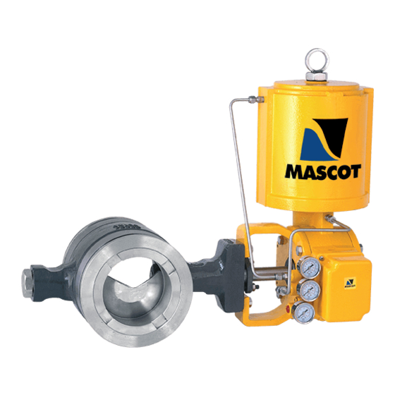
VFlo
Control Valves
CAUTION :
1.
Use pressure relief valves for high pressure
piping.
2.
Use explosion proof valves/accessories for
dangerous media piping.
3.
Use fire safe valves for piping where chances of
fire by external means.
4.
Use seismic proof valves where chances of
earthquake are frequent.
5.
Check whether location of the valve mounting is
of the same service/application as specified on
the marking plate.
Advertisement

Summary of Contents for MASCOT VFlo
- Page 1 Installation, Operation, Maintenance Instructions VFlo Control Valves CAUTION : Use pressure relief valves for high pressure piping. Use explosion proof valves/accessories for dangerous media piping. Use fire safe valves for piping where chances of fire by external means. Use seismic proof valves where chances of earthquake are frequent.
-
Page 2: General Information
CAUTION : The full torque load of the actuator cannot be conditions. **Lengths are based on ANSI B16.5 stud bolts and taken by the VFlo valve shaft. The shaft could twist and/or raised face ends. shear if the ball were to seize and full torque continued. -
Page 3: Preventive Maintenance
(*See Figure 4 for seal configurations and item numbers.) Stationary Post Design Figure 1: 3", 12" and 16" VFlo Body Assembly with Rotating Post Design Note : Item numbers correspond to bill of material of Valve. Please refer to it for specific part numbers. -
Page 4: Disassembly And Reassembly
Removing Actuator From Body lock ring need removal, then the re-taining ring is to be The design of the 3 to 12-inch VFlo valves permits disassembly removed, lock ring and seal retainer finally. The retaining ring without removing the Mascot actuator. However, it is advisable can be forced out using a flat-headed screwdriver and pliers - to remove the actuator. - Page 5 The shaft and post are to be inspected for galled surfaces or insert thrust bearing.) The post must be positioned so that the scratches. To achieve optimum performance, VFlo shafts and pin hole in the post and ball are aligned. (For 6 through 12- posts are given a very smooth finish.
- Page 6 Remounting the Actuator includes a consid-erable amount of axial play between the Prior to initiation of the mounting of a Mascot actuator on the ball and shaft.) valve body, verify that the ball rotation matches the actuator For 1 through 2-inch designs, make sure the ball surface is rotation and complies with the air failure requirements.
- Page 7 VFlo Control Valves Table IV: Optional VFlo Tools Entire actuator assembly is to be slided onto the shaft. Valve Retainer Shaft/Post The yoke needs to be bolted to the valve body. Size Tool Bearing Tool The actuator lever arm should be positioned on the shaft so...
- Page 8 MASCOT VALVES PVT. LTD. 166 / 167, G I D C, Naroda, Ahmedabad : 382330. India Phone : +91 79 22821619/22823369, Fax : +91 79 22822430 Email : info@mascotvalves.com / web : www.mascotvalves.com...