Table of Contents
Advertisement
Quick Links
Advertisement
Table of Contents

Subscribe to Our Youtube Channel
Related Manuals for ITS Telecom WaterFeature8 A Series


Summary of Contents for ITS Telecom WaterFeature8 A Series
- Page 1 Industrial Monitoring Kit...
- Page 2 Integrated Treatment Systems, LLC WaterFeature8™ A-Series Sensor Interface System NSTRUCTION ANUAL 2021 CTOBER...
-
Page 3: Table Of Contents
Table of Contents ................................................2 VERVIEW 1.1 Configurations ............................................2 1.2 Voltage Isolation ...........................................2 2 WaterFeature8 B ........................................3 OARD OMPONENTS .............................................5 EVICE PECIFICATIONS 3.1 Power Consumption ..........................................6 3.2 Sensor Interface System Enclosure ....................................6 ..............................................7 NSTALLATION 4.1 Mounting Dimensions, WaterFeature8 Circuit Board ................................7 4.2 Installation Procedure, System Builder Kit ..................................7 4.3 Mounting Dimensions, Sensor Interface System ................................8 4.4 Installation Procedure, Sensor Interface System ................................8... -
Page 4: Overview
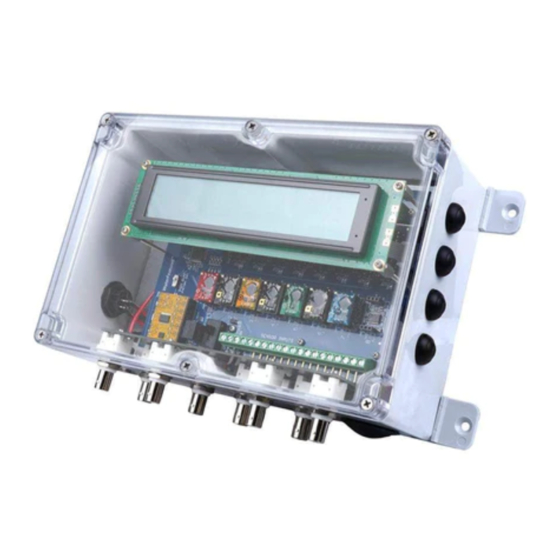
Includes Includes VERVIEW Model Panel Includes Sensor 4-20 mA Integration Enclosure Connectors The WaterFeature8™ (WF8™) A-series water quality monitoring system Outputs is designed and manufactured by Integrated Treatment Systems, LLC WF8-SBK- (ITS®) to accomplish these objectives: Terminals 0420 • Monitor up to eight (8) different water quality monitoring WF8-SBK- Terminals 0000... -
Page 5: Waterfeature8 Board Components
Atlas Scientific, LLC 8:1 Serial Expander P/N COM-102 2 WaterFeature8 B OARD OMPONENTS Generations 1 and 2 of the WaterFeature8 system use the The WaterFeature8 is designed specifically to work with Atlas Scientific, Atlas Scientific, LLC Serial Expander to automatically identify LLC EZO sensor interpreting circuits. - Page 6 Analog Output Terminals Connect analog output wires here. The WaterFeature8 board considered sourcing analog device; compatibility use a sinking or dual sourcing/sinking analog input card. 4 of 24...
-
Page 7: Device Specifications
EVICE PECIFICATIONS • Temperature: Celsius ( The WaterFeature8 is designed to exclusively work with Atlas Scientific EZO sensor circuits. Sensors that are compatible with EZO circuits • Flow: gallons per minute (gpm) should theoretically also function with the WaterFeature8. However, Integrated Treatment Systems, LLC is unable to validate all commercially •... -
Page 8: Power Consumption
The following table describes the numerical ranges and resolutions of both the LCD HMI and the analog output current loops. Display Value Analog Output Values (5 Digits) (16-bit Signal Resolution is 0.0000153 mA) EZO Circuit Type Theoretical Display High Unit Display Calibration Points Output Resolution... -
Page 9: Installation
EZO circuits can be installed before or after mounting the NSTALLATION circuit board. Depending on the product you have purchased, the WaterFeature8 system will require different installation methods. System Builder Install up to eight (8) EZO circuits and/or WF-IB voltage Kits are intended to be installed in user provided assemblies and/or isolation circuits. -
Page 10: Mounting Dimensions, Sensor Interface System
automatically enter Local State and continually poll each EZO circuit in ascending numerical order at a rate of approximately two circuits per second but varies based on the specific types of circuits that are mounted. The order/sequencing of EZO circuits does not matter. The LCD screen will display the channel number of each EZO based on its insertion location on the WaterFeature8 board. -
Page 11: Wf-Ib Isolation Board Installation
Connect the 120VAC-24VDC power adapter from a U.S. standard 2-prong wall outlet to the DC input power jack on the bottom of the Sensor Interface System enclosure. Connect sensors to the BNC terminals located on the bottom face of the Sensor Interface System. Carefully install the provided CR2502 coin cell battery by aligning the positive side of the battery with the ‘+’... -
Page 12: Ezo Circuit Setup
IRCUIT ETUP At this point the AutoConfig function has finished and the WF8 system There are three ways to set up Atlas Scientific, LLC EZO circuits to immediately reboots. After rebooting the WF8 Home screen will function with the WaterFeature8 system: correctly display the proper EZO circuits in the correctly installed Using the AutoConfig function available on firmware v1.02 channels. - Page 13 • • Disable continuous readings: Disable ‘OK’ response function: *OK,0 • Disable ‘OK’ response function: *OK,0 The WaterFeature8 is designed to operate in the optimal range of a 1.0 K-value conductivity sensor, although other K-value sensors may Oxidation Reduction Potential (ORP) work in the range of 0.003 to 200,000 μS/cm.
-
Page 14: Starting The Waterfeature8
there will be one or more submenu selection buttons depending on WaterFeature8 TARTING THE the current firmware version. The Home screen looks like this: Start the WaterFeature8 System Builder Kit by applying 24 VDC and Ground to the input terminal block and turning the [POWER] switch to the ON position. -
Page 15: Calibration Instructions
Prepare the desired sensor and place in ambient air or ALIBRATION NSTRUCTIONS calibration solution as required by the sensor. If placed in Many sensor/EZO combinations can be calibrated using the on-board calibration fluid, ensure air bubbles are not trapped at the Calibration submenu (Cal-->) to reset the sensor known points to face of the sensor which may skew calibration values. -
Page 16: Calibration Tips
After pressing Cal --> [SW1] on the LCD HMI, follow the on-screen display 1288 for [Cal Mid] and 8000 for [Cal High]. These values will prompts to complete calibration. properly update to display in μS/cm on the Main Menu. EC calibration should be done while the EZO fluid temperature is set 7.2.3 pH to 25C, which is the factory default setting, and will remain at this pH may be calibrated at the following points:... - Page 17 • Revising the K-value of a DC-pulse type flow meter requires performing flow calibration test. Visit www.intreatsys.com for recommendations on calibrating flow meters. Note, turbine style dc-pulse meters are not known to be highly accurate. Do not use these meters for legally required flow monitoring such as regulatory permit compliance flow reporting.
-
Page 18: Temperature Compensation
EMPERATURE OMPENSATION If no temperature compensation channel is currently assigned for the The Temperature Compensation (TComp or TCp-->) feature is active channel (this is the default condition until a temperature designed to improve the accuracy of pH, DO, and EC EZO circuits by compensation RTD channel is assigned), the octothorpe (# sign) is supplying liquid temperature data from an RTD EZO with temperature displayed. -
Page 19: Remote Communications
Power-cycling the WF8 will restore local control on bootup. However, EMOTE OMMUNICATIONS if remote commands are being received from a remote client, Remote Starting with Firmware version 2.01, the WaterFeature8 operating State may become active as soon as boot procedures are complete. system has two distinct modes: 1) Local State, and 2) Remote State. -
Page 20: Command Definitions
to Local State DOES NOT prevent remote commands from being {CO2} Carbon Dioxide gas submitted to the WaterFeature8, nor does it prevent the WaterFeature8 {O2_} Oxygen gas from performing those commands. {HUM} Relative Humidity If the system is in Local State and a user is performing on-site operation, when a remote command other than rem #### {PRS} ... -
Page 21: Remote State Best Practices
WFreadunits :: Performs one complete polling Setup should not be modified unless the user intends to primarily cycle sending the EZO command to each keep the system in Remote State. Modifying these configuration populated socket. The return string format is settings could interfere with Local State functionality and may render {CH#,EZO,vvvv}[CR] after each socket reading. - Page 22 running the Temperature Compensation assignment WFreadall is the only Remote State command that will checks during the boot process. When the TCp boot check update the analog output values. observes a change in EZO population the WaterFeature8 • requires local user intervention to acknowledge the change If the onboard 4-20 mA outputs are used for an external in EZOs (by pressing [SW4]), however, the remote user will process control system(s), as opposed to using the remotely...
-
Page 23: Bill Of Materials
10 B ILL OF ATERIALS The following items are included with the WaterFeature8 System Builder Kit: Description Source Part Number WaterFeature8 Integrated PCBA-1.3 A-Series Circuit Treatment Board Systems 4x40 LCD Display Newhaven NHD-0440AZ-FL- Display International Display Ribbon HF365/18SF Cable Ribbon Cable IDC Amphenol 71600-018LF Connector... -
Page 24: Wf8 Version History & Ezo Compatibility
11 WF8 V & EZO ERSION ISTORY 1.01 2.12 2.11 2.10 2.12 2.10 <2.0 1.02 OMPATIBILITY 2.13 2.12 2.10 2.13 2.10 2.00 1.14 The following version data provides a historical record of hardware 1.20* 2.13 2.12 2.10 2.13 2.10 2.01 and firmware development to date. -
Page 25: Guarantee
The following activities will explicitly void this limited warranty: 12 G UARANTEE • Failure to register your product with ITS. Visit 12.1 Warranty Statement www.intreatsys.com/warranty for product registration This limited warranty is governed by and construed under the laws instructions. of the State of Iowa. -
Page 26: Contact Us
12.4 Contact Us We are excited to continue developing cost effective solutions to solving water quality challenges and are looking forward to your suggestions to improve our products. Feel free to contact us in any of the following ways: Email: custsomerservice@intreatsys.com Web: https://www.intreatsys.com/contact-its... - Page 27 Integrated Treatment Systems, LLC www.intreatsys.com sales@intreatsys.com customerservice@intreatsys.com ©2021 Integrated Treatment Systems. Product specifications subject to change without notice. ITS and the ITS Logo are registered trademarks of Integrated Treatment Systems, LLC. WaterFeature8, WF8, and the corresponding Logos are trademarks of Integrated Treatment Systems, LLC. Visit www.intreatsys.com/wf8 for current product information, including the latest version of this manual.
Need help?
Do you have a question about the WaterFeature8 A Series and is the answer not in the manual?
Questions and answers