Advertisement
DL Series
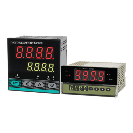
DL8A/DL9A Voltage/Ampere Meter User Manual
Features:
⊙Accuracy: 0.5%F.S.
⊙AC/DC universal (for AC signal it measures true value).
⊙Different input channel has different range, wide measuring range.
⊙Two Hi/Lo setting alarm output.
⊙With analog output 4-20mA.
⊙RS485 communication interface, Modbus RTU protocol.
Model
Input channel and Range
①When you use the meter, please pay attention that input channel should correspond to range,
otherwise, the meter will be malfunction.
AC signal, aviliable for 0~200Hz. When frequency is higher than 100Hz, the measuring accuracy
is ±1%FS.
II. Technical Specification
Power Supply
AC/DC 100~240V 50Hz/60Hz DC 24V(Need to be ordered)
Display range
0.001-9999 float decimal point display
Accuracy
±0.5%F.S ±2digits(For AC signal frequency under 100Hz)
Analog output
4~20mA load capacity≤600Ω, accuracy:±0.5%F.S
RS485 communication interface,Modbus RTU Protocol
Communication
Relay capacity
AC 250V/3A or DC 30V/5A
Between power supply connector and other connectors, relay output
Dielectric Strength
connectors and other connectors, AC 1800V leakage current 0.5mA,
60S; Between input signal connectors and low voltage signal output
connectors, DC 600V leakage current 0.5mA,60S
Insulation Impedance
≥100MΩ/500V DC
Working environment
Temperature:0-50℃
Sampling rate
5 times/S
III. Panel Illustration
Displaying measuring value/parameter code
AL1: Alarm 1#
AL2:Alarm 2#
Displaying parameter
set value/input code
KKDL8A-C01E-A/1-20190723
Commu-
Alarm
Analog output
nication
2 alarm
NO
NO
2 alarm
4-20mA
NO
2 alarm
4-20mA
RS485
2 alarm
NO
NO
2 alarm
4-20mA
NO
2 alarm
4-20mA
RS485
2 alarm
NO
NO
2 alarm
4-20mA
NO
2 alarm
4-20mA
RS485
②Input signal < 1.2 times of range.
③When measuring
Humidity:≤85%RH
V: Voltage indication lamp
A(mA): Current indication lamp
Decrease key
Increase key
Shift key
SET: Parameter select/confirm key
For your safe, please read the below content carefully before you use the meter!
Safe Caution
Please read the manual carefully before you use the meter.
※ Please comply with the below important points.
Warning
An accident may happen if the operation does not comply with the instruction.
Notice
An operation that does not comply with the instruction may lead to product damage.
The instruction of the symbol in the manual is as below.
An accident danger may happen in a special condition.
Warning
1.A safty protection equipment must be installed or please contact with us for the relative
information if the product is used under the circumstance such as nuclear control, medical
treatment equipment, automobile, train, airplane, aviation and equipment etc.. Otherwise, it
may cause serious loss, fire or person injury.
2.A panel must be installed, otherwise it may cause creepage (leakage).
3.Do not touch wire connectors when the power is on, otherwise you may get an electric shock.
4.Do not dismantle or modify the product. If you have to do so, please contact with us first.
Otherwise it may cause electric shock and fire.
5.Please check the connection number while you connect the power supply wire or input signal,
otherwise it may cause fire.
Caution
1
.This product cannot be used outdoors. Otherwise the working life of the product will become
shorter, or an electric shock accident may happen.
2.When you connect wire to the power input connectors or signal input connectors, the
moment of the No.20 AWG (0.50 mm) screw tweaked to the connector is 0.74n.m - 0.9n.m.
Otherwise the connectors may be damaged or get fire.
3.Please comply with the rated specification. Otherwise it may cause electric shock or fire, and
damage the product.
4.Do not use water or oil base cleaner to clean the product. Otherwise it may cause electric
shock or fire and damage the product.
5.
This product should be avoid working under the circumstance that is flammable, explosive, moist,
under sunshine, heat radiation and vibration. Otherwise it may cause explosion.
6.
In this unit it must not have dust or deposit, otherwise it may cause fire or mechanical malfunction.
7.Do not use gasoline, chemical solvent to clean the cover of the product because such solvent can
damage it. Please use some soft cloth with water or alcohol to clean the plastic cover.
I. Code Illustration
V. Operations
Default channel
and range
① The second row LED is defaulted to display range and input channel alternately after
power on, press ( ) to display range only, press ( ) to returns to default display
IN3:600V
② In the measuring status, press SET >3S to enter setting menu.
③ When modifying setting value, press
point; after modifying, press SET key to confirm and enter next menu. After setting,press SET
key more than 3S to exit menu; if there is no operation for a long time, it will exit automatically.
IN1:5A
No.
Paremeter code
IN2:1000mA
1
INP
2
Ad1
3
AL1
4
Hy1
5
Ad2
6
AL2
7
Hy2
8
Ct
9
PS
10
rH
11
rL
12
Add
13
bAd
14
LCK
Power On
Measuring status
operation setting
Power
supply
ON
All
LED
are
on
Measuring
Status
Version code
Range
A:AC/DC current
10:No RS485 18:With RS485
B:One alarm C:Two alarms
A:No alarm
R:Relay alarm
Blank: No analogue output
I:4~20mA analogue output
8: 48H*96W*100L
DL8A series voltage/ampere meter
/
to change value; press ( ) key to shift decimal
Setting range
Factory value
For range A1000, the default
one is IN1; for range A1, the
IN1~IN3
default one is IN2;for range
V600,the default one is IN3
H or L
H
-1999~9999
90% of measuring range
-1999~9999
1.000
H or L
L
-1999~9999
10% of measuring range
-1999~9999
1.000
1.000
0~9999
0.000
-1999~9999
-1999~9999
maximum of the range
-1999~9999
minimum of the range
0~255
001
4.8 or 9.6
9.6
0~255
000
Input Channel Selection:
Chosen from "IN1~IN3"
The first alarm mode:
H:High;L:Low
The first alarm value
setting
The first alarm hysteresis.
For example, if Ad1=H,
AL1=50, HY1=5, when
measuring value≥50(AL1),
alarm is actived;when it
≤45 (AL1-HY1), alarm is
deactived.
The second alarm mode:
same as Ad1.
The second alarm value
setting: same as AL1
The second alarm
hysteresis: same as HY1.
V:AC/DC voltage
9: 96H*96W*100L
Indication
AL,HY,Ct,PS,
rH,rL have the
sameunit as
the Range.
Current Transforming: it is only
for 5A range or 75mV spliter
current input. If its value is set
as the the ratio of external CT
or spliter, the actual range
should be CT*5. For other
situation, CT is set as 1.
Amendment value,displaying
value=measured value +PS,
factory setting: PS=0
Analog output high limit
setting:when measured value=
rH set value,the corresponding
analog output is 20mA.
Analog output low limit setting:
when measured value = rL set
value, the corresponding
analog output is 4mA
Add:Meter communication
address
Communic:ation baud rate:
4.8kbps、9.6kbps for option.
Lock key
Lock=000,read and write
Lock=010,read only
Advertisement
Table of Contents

Subscribe to Our Youtube Channel
Related Manuals for KONEL DL Series

Summary of Contents for KONEL DL Series
- Page 1 For your safe, please read the below content carefully before you use the meter! DL Series Safe Caution Please read the manual carefully before you use the meter. ※ Please comply with the below important points. Warning An accident may happen if the operation does not comply with the instruction.
- Page 2 V. Connection drawing VIII. Communication This meter using Modbus RTU communication protocol, and it can run RS485 half-duplex communication. Read function code is 0x03, write function code is 0x10, 16-bit CRC checking is applied. The meter don’t feedback error message. The communication data type is 32 bit integer data, true code stands for positive number, complemental code stands for negative number, data rate is 0.001;for example, if the meter data received by host is 5000, then meter data * rate = original data (5000*0.001=5.000).
Need help?
Do you have a question about the DL Series and is the answer not in the manual?
Questions and answers