
Subscribe to Our Youtube Channel
Summary of Contents for Crow FW2 MERLIN PRO
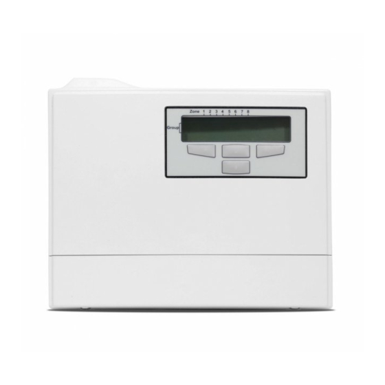
- Page 1 FW2 MERLIN PRO Manual ============================== ROGRAMMABLE TAND ALONE IRELESS RANSCEIVER Installation Programming Guide ELECTRONIC ENGINEERING LTD. WWW.THECROWGROUP.COM P/N 7106452 Rev. C...
-
Page 2: Table Of Contents
EYPAD Navigating the Screens ......................4 ) ......................5 EMORY VENT Displaying the Event Log ...................... 5 Setting the Date and Time ....................5 INSTALLING THE FW2 MERLIN PRO ..................6 ......................7 NSTALLATION IAGRAMS .....................9 ROGRAM EQUENCE LCD Display Symbol Table ....................9 Entering Numbers ......................... -
Page 3: Product Description
The FW2 MERLIN PRO has eight outputs (output no.8 is a dry contact) that can be connected to Zone inputs on any wired Control Panel unit, or other suitable device. -
Page 4: Way Wireless Accessories
2 Way Wireless Accessories All of the following devices are compatible with FW2 MERLIN PRO. 2 Way Wireless key Unit 2 Way Wireless PIR detector 2 Way Wireless Door contacts 2 Way Wireless Smoke detector User Mode Using the Display and Keypad When the unit powers ON the unit displays the Menu screen as shown below. -
Page 5: Memory (Event Log)
Setting the date and the time is done using the Up and Down arrow ▲▼ buttons. The FW2 MERLIN PRO contains a Real Time clock with back up batteries so that the date and time is not erased when external power is removed from the FW2 MERLIN PRO. -
Page 6: Installing The Fw2 Merlin Pro
3. Drill the two marked holes and install the bracket with two screws (see Figure 1). 4. Assemble the FW2 MERLIN PRO on the holder and mark the third drill hole (see Figure 2). 5. Remove the FW2 MERLIN PRO and drill the third hole. -
Page 7: Installation Diagrams
Installation Diagrams Figure 1: Attach the Screw Bracket to a Flat surface. Figure 2: Attach the Unit to the Screw bracket. Figure 3: Installing the Third Screw Figure 4: Replacing the Service Cover... - Page 8 To the C.P Input Zones Not in use 12V from the C.P or any P.S 12V DC To the C.P Output Active "Low" while Arm To the C.P Tamper Figure 5: Unit Power and Output Connection Programming the Unit NOTE The unit has to be fed only from a limited power source as per Standard EN/IEC 60950-1 latest edition, sub-clause 2.5, and be of SELV type.
-
Page 9: Program Sequence List
3. Locate the detectors and the FW2 MERLIN PRO close to the point you want to install them and perform the Radio signal strength test. 4. Change the password and record it for your/your customer files. -
Page 10: Setting The Clock
Setting the Clock The following sections describe in detail how to set each mode. 1. From the Main menu, press the ► button. The Memory screen is displayed. 2. Press the ▼ button to display the Date/Time screen. 3. Press the ◄ button to confirm. 4. -
Page 11: Installer Mode
11. Press the ◄ button to set the Hour. 12. Press either the ▲ or ▼ buttons to select the Minutes. 13. Press the ◄ button to set the Minutes. The time and date are updated and the Date/Time screen is displayed. Installer Mode Accessing the Installer Mode 1. -
Page 12: Adding A Fw2 Wireless Device (Add Zone)
This mode is used for assigning a Group and a Zone for each detector or key. First assign a Group and Zone and then on the selected device open the service cover and press the tamper switch. This sends a signal to FW2 MERLIN PRO to learn and complete the device setup. -
Page 13: Adding A Remote Control Key (Wireless Key)
Any Group already selected displays an S in that position. 4. Press the ▲ or the ▼ buttons select a Group. 5. Press the ◄ button to accept the group selection. Any Zone already selected displays an S in that position. The unit beeps while waiting a tamper signal sent from the selected device. - Page 14 Press the ▼ button to display the 1 second screen. In this mode the output is activated for 1 second. Press the ▼ button to display the 3 second screen. In this mode the output is activated for 3 seconds Press the ▼...
-
Page 15: Clear Zone
5. Press the ▲ or ▼ buttons to choose an output. Positions 1 to 7 are NC (dry contacts) and position 8 is a form C relay (NO/NC). The Ready screen opens and the unit beeps waiting for a remote key signal. 6. -
Page 16: Clear Remote
6. Press the ▲ or ▼ buttons to select a Zone. 7. Press the ◄ button to set the Zone. The unit will beep twice and the Zone is cleared. Clear Remote 1. Enter the Installer mode. See Accessing the Installer Mode on page 11 for instructions on how to enter this mode. -
Page 17: Changing The Password
Changing the Password 1. Enter the Installer mode. See Accessing the Installer Mode on page 11 for instructions on how to enter this mode. 2. Press the ▼ button to scroll to the Change Password Screen. 3. Press the ◄ button to confirm. 4. -
Page 18: Clear History
3. Press the ◄ button to confirm. The RSSI screen opens. 4. Either operate a tamper switch of one of the devices or press the remote key button. The signal strength is displayed on the screen. 5. Press the ◄ button to clear the screen. 6. -
Page 19: Arm To Output
Arm to Output Enter the Installer mode. See Accessing the Installer Mode on page 11 for instructions on how to enter this mode. 2. Press the ◄ button to confirm. 3. Press the ▲or ▼ button to choose the Output you want to assign for arming the C.P. -
Page 20: Remotes Log
NOTE While you assign one Outputs to buzzer, on every Output activation will activate the buzzer until the Output will restore. Remotes Log Enter the Installer mode. See Accessing the Installer Mode on page 11 for instructions on how to enter this mode. -
Page 21: Version
2. Press the ◄ button to confirm. 7. Press the ▲or ▼ button to choose Yes or No. 8. Press the ◄ button to confirm. NOTE Disables the detector detection but report the tamper alarm continues and clears the current alarms on LCD Version 1. - Page 22 See Accessing the Installer Mode on page 11 for instructions. 2. Press the ▼ button to scroll to the Defaults Screen. 3. Press the ◄ button to confirm. 4. Press the ◄ button to confirm acceptance. The unit is formatted. Formatting has completed successfully and the Main screen is displayed.
-
Page 23: Functions
Functions NOTE While the FW2 MERLIN PRO is in normal operation it must display the main screen or reported events will be ignored. Function Description Outputs Outputs 1 to 8 and Tamper are dry contact (Not relative to GND) Outputs 1 to 7 are Normally closed. -
Page 25: Technical Specifications
Technical Specifications Input Voltage 10 to 15V DC Current Max. 130mA Consumption Outputs Outputs 1 to 7 Solid State Relay OPTO MOSFET, Contact Resistance 17 ohm Maximum Contacts Current - 100mA Output 8 Relay, Contact Resistance- 0 ohm Maximum Contacts Current - 1A Tamper OPTO MOSFET, Contact Resistance 17 ohm Maximum Contacts Current - 100mA... - Page 27 In no case shall Crow be liable to anyone for any consequential or incidental damages (inclusive of loss of profit, and whether occasioned by negligence of the Crow or any third party on its behalf) for breach of this or any other warranty, expressed or implied, or upon any other basis of liability whatsoever.
- Page 28 12 Kineret St. Airport City, 70100 Israel Tel. +972 3 9726000 Fax. +972 3 9726001 sales@crow.co.il support@crow.co.il www.thecrowgroup.com CROW LATIN AMERICA USA INC. 7200 NW 19 st. Suite 307 Miami FI 33126, USA Tel. +305 513 4001 Fax. +305 513 4005 rejane@crowlatinamerica.com www.crowlatinamerica.com...
Need help?
Do you have a question about the FW2 MERLIN PRO and is the answer not in the manual?
Questions and answers