Table of Contents
Advertisement
Quick Links
Native IP Digital Microwave
This is an unpublished work the copyright in which vests in Comba International ("Comba"). All rights reserved.
The information contained herein is confidential and the property of Comba and is supplied without liability for errors or omissions.
No part may be reproduced, disclosed or used except as authorised by contract or other written permission. The copyright and the
foregoing restriction on reproduction and use extend to all media in which the information may be embodied.
ML-FOS QI
ENU Status: 1-0-0
ML-FOS Installation Guide
ML-FOS
Full Outdoor System
INSTALLATION GUIDE
Copyright - refer to title page
The information contained herein is the
responsibility of and is approved by the
following, to whom all enquiries should
be directed in the first instance:
Comba Telecom
Page 1
Advertisement
Table of Contents

Summary of Contents for COMBA ML-FOS
- Page 1 This is an unpublished work the copyright in which vests in Comba International ("Comba"). All rights reserved. The information contained herein is confidential and the property of Comba and is supplied without liability for errors or omissions. No part may be reproduced, disclosed or used except as authorised by contract or other written permission. The copyright and the foregoing restriction on reproduction and use extend to all media in which the information may be embodied.
-
Page 2: Table Of Contents
ML-FOS Installation Guide CONTENTS Section Page CONTENTS ........................... 2 INDEX TO FIGURES AND TABLES ..................3 HISTORY..........................4 ISSUE CONTROL ......................... 5 REFERENCE ........................6 GLOSSARY OF TERMS ....................... 7 SAFETY NOTICES AND ADMONISHMENTS..............8 SERVICING POLICY AND RETURN OF EQUIPMENT ............9 GENERAL INFORMATION .................... -
Page 3: Index To Figures And Tables
ML-FOS Installation Guide INDEX TO FIGURES AND TABLES Figure 1: FOS interface description ......................11 Figure 2: Insert the optical module into the payload interface ..............12 Figure 3: FOS with optical module Installed ..................12 Figure 4: Alignment key on antenna waveguide...................13 Figure 5: Alignment hole on FOS waveguide port ................13... -
Page 4: History
ML-FOS Installation Guide HISTORY Change No. Details Of Change 1-0-0 First draft finished in Nov 2009. ML-FOS QI Copyright - refer to title page Page 4 ENU Status: 1-0-0... -
Page 5: Issue Control
ML-FOS Installation Guide ISSUE CONTROL Date Section ML-FOS QI Copyright - refer to title page Page 5 ENU Status: 1-0-0... -
Page 6: Reference
ML-FOS Installation Guide REFERENCE 0.5.1 ML-FOS-YH Initial user manual released in Oct 2009. ML-FOS QI Copyright - refer to title page Page 6 ENU Status: 1-0-0... -
Page 7: Glossary Of Terms
ML-FOS Installation Guide GLOSSARY OF TERMS 10Base-T 10Mbit/s Baseband Unshielded Twisted Pair Cable Automatic Gain Control Alarm Indication Signal Alarm ATPC Automatic Transmit Power Control Auxiliary Data Channel Add/Drop Multiplexer Asynchronous Transfer Mode Bit Error Rate BERT Bit Error Rate Tester... -
Page 8: Safety Notices And Admonishments
ML-FOS Installation Guide SAFETY NOTICES AND ADMONISHMENTS This document contains safety notices in accordance with appropriate standards. In the interests of conformity with the territory standards for the country concerned, the equivalent territorial admonishments are also shown. Any installation, adjustment, maintenance and repair of the equipment must only be carried out by trained, authorized personnel. -
Page 9: Servicing Policy And Return Of Equipment
SERVICING POLICY AND RETURN OF EQUIPMENT The repair of individual units and modules of this equipment is not considered practicable without factory facilities. It is, therefore, the policy of Comba whereby faulty units or modules are returned to the local agent for repair. -
Page 10: General Information
ML-FOS Installation Guide GENERAL INFORMATION Comba Digital Microwave System allows transmission links to be established rapidly and easily to meet a variety of transmission needs, brings cost savings and helps rapid network rollout. This solution comprises of: antenna, outdoor unit and indoor unit. -
Page 11: Package Accessories
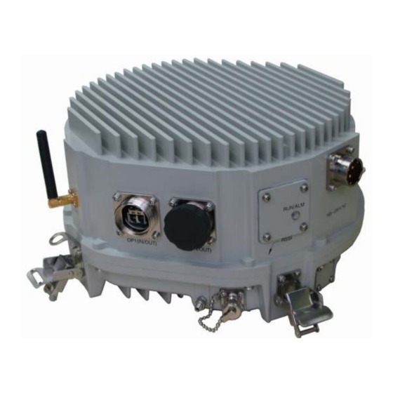
ML-FOS Installation Guide PACKAGE ACCESSORIES Please check the accessories against the packing list for damage and completeness. FOS INTRODUCTION FOS is the Full Outdoor System, integrating IDU and ODU together, which is applicable for the outdoor application. Wireless access to CIT enables the easy commissioning and maintenance of FOS. -
Page 12: Fos Installation
ML-FOS Installation Guide FOS INSTALLATION OPTICAL MODULE INSTALLATION Take figure below as a guide to install optical module before attach FOS to antenna. • Insert the optical module into payload interface “OPT1 (IN/OUT)”. Optical Module Figure 2: Insert the optical module into the payload interface •... -
Page 13: Fos Attachment To Antenna
FOS can be directly attached to antenna by secure four locking buckles. Follow steps below to finish FOS attachment to antenna. • Align antenna polarization (refer to Comba 0.3m_0.6m Antenna QI 1-0-0 / Comba 1.2m Antenna QI 1-0-0). • Align FOS onto antenna by matching the alignment holes on the FOS waveguide port with the alignment keys on antenna waveguide. - Page 14 ML-FOS Installation Guide • Attach FOS onto the rear of antenna and hook each locking buckle to secure FOS to antenna. Hook each locking buckle Figure 6: Attach FOS to antenna ML-FOS QI Copyright - refer to title page Page 14...
-
Page 15: Fos Cable Connection
ML-FOS Installation Guide FOS CABLE CONNECTION 4.3.1 GROUNDING THE FOS The FOS should be properly grounded before connecting any other cables to it. A ground terminal located on the FOS is used for grounding. This ground terminal must be electrically connected to the tower mounted with antenna. -
Page 16: Powering The Fos
ML-FOS Installation Guide Fix the waterproof cover. Figure 9: Payload cable connection-2 4.3.3 POWERING THE FOS Figure below shows the FOS power supply cable with lightning arrester. Figure 10: Power supply cable Note: The power supply cable is 5m in length, if it is not long enough, please extend it manually. - Page 17 ML-FOS Installation Guide Connect the end with lightning arrester to the power input interface, the other end with three-way plug goes to the power supply source. Match the socket and plug as indicated in the figure below. Alignment pin Alignment Hole...
-
Page 18: Commissioning
This section focuses on the local commissioning via the CIT wireless connection, please refer to the separate NMS manual for ML-FOS NMS. EQUIPMENT POWER-UP Before applying power, check that the expected voltage, current, and power levels do not violate any ratings. - Page 19 ML-FOS Installation Guide Step 3: In the prompt window, choose the correct “TCP/IP (Winsock)” in the “Connect using” menu, set up the “Host address” and “Port number” as indicated in the screenshot below. Note: “192.168.0.1” is the default IP address of any FOS, while the default port setting is 5000.
- Page 20 ML-FOS Installation Guide Step 7: The window below will be viewed to indicate successful connect to the system, insert the password “admin” and press ENTER to enter the system. Figure 16: Launch the CIT terminal – step 7 ML-FOS QI...
-
Page 21: Wireless Access To Cit
ML-FOS Installation Guide 5.2.2 Wireless Access to CIT Read the CD which is shipped together with the CIT wireless module, and then follow steps below to achieve the wireless access to CIT. Step 1: Double click on the icon below to install the driver of wireless CIT module, “CP210x_VCP_Win2K_XP_S2K3”. - Page 22 ML-FOS Installation Guide Step 4: Connect the CIT wireless access module which should be ordered separately to PC via USB interface. Step 5: Double click on the icon below to run the “apc220_v12: Figure 20: Installation of apc220_v12 Step 6: In the prompt window, set up the “RF frequency” and “RF TRx rate” as indicated in the screenshot below, select the last option in the “PC series”...
- Page 23 ML-FOS Installation Guide Step 8: In the pop up window, choose the correct “COM” in the “Connect using” menu; it should be consistent with the “PC series” setting in step 2. Step 9: Click “Bits per second” to set the properties for the selected COM, in this case, select 9600 as...
- Page 24 ML-FOS Installation Guide Step 11: Click “OK” to access the terminal screen. Select File -> Properties -> Setting, in the prompt window as following, select “VT100” in the “Emulation” menu and click “OK” to confirm. Figure 25: Launch the CIT terminal-5 Step 12: The window below will be viewed to indicate successful connect to the system, insert the password “admin”...
-
Page 25: Cit Top Menu
ML-FOS Installation Guide CIT TOP MENU RF Alarm RF Alarm RF Lost RF Lost RF RSL RF RSL RF Tx Power RF Tx Power RF -5V RF -5V RF PA-I RF PA-I RF Tx IF RF Tx IF Current Alarm... - Page 26 ML-FOS Installation Guide The descriptions of each menu are listed in the table below: Menu Description Read/Writ Alarm Alarming Parameters RF Alarm Current alarm reading Read RF Lost Read and mask/unmask the RF Lost alarm Read/Set RF Tx Power Read and mask/unmask the RF transmitter power alarm...
-
Page 27: Cit Control
ML-FOS Installation Guide CIT CONTROL After entering the CIT successfully, follow up with parameter configurations for ML-GH. The CIT can be controlled by using keyboard. The mark “>” indicates that there are submenus exist, press “ENTER” to access to the submenu; press the direction buttons to select the submenu. Refer to... -
Page 28: Read And Set Parameters
ML-FOS Installation Guide READ AND SET PARAMETERS Once accessing to the menu, users can proceed to read or write the desired data. As it is presented in the figures below: select a desired data via “Tab” and press “ENTER” to confirm, and then it will be displayed at “Cur”... -
Page 29: Set Up A Working Link For 1+0 Configuration
SET UP A WORKING LINK FOR 1+0 CONFIGURATION To set up a working link, follow: Install Antenna (refer to Comba 0.3m_0.6m Antenna QI 1-0-0 / Comba 1.2m Antenna QI 1-0-0). Coarse antenna adjustment (refer to Comba 0.3m_0.6m Antenna QI 1-0-0 / Comba 1.2m Antenna QI 1-0-0). -
Page 30: Maintenance
• Antenna systems should be inspected once a year by qualified personnel to verify proper installation, maintenance, and the condition of equipment. Comba disclaims any liability or responsibility for the results of improper or unsafe installation practices. ML-FOS QI... -
Page 31: Appendix: Rma (Return Material Authorization) Form
ML-FOS Installation Guide APPENDIX: RMA (RETURN MATERIAL AUTHORIZATION) FORM Comba Telecom Ltd. 611 East Wing, No. 8 Science Park West Avenue, Hong Kong Science Park,Tai Po, Hong Kong Tel: +852 2636 6861 Fax: +852 2637 0966 RMA Request Form Date:...
Need help?
Do you have a question about the ML-FOS and is the answer not in the manual?
Questions and answers