Table of Contents
Advertisement
Available languages
Available languages
Quick Links
ATS1210/1211/1220 4/8-Zone DGP Installation
Sheet
EN DA DE ES
FI
FR
EN: Installation Sheet
Mounting the unit
The PCB can be mounted in any existing ATS series enclosure
that supports the BB format.
Connections
J1
•
COMMS +, −: 12 VDC power supply. It is recommended
that where the distance between an ATS1220 and the
nearest device is more than 100 meters, a separate power
supply be used.
•
COMMS D+, D−: Positive and negative data connection of
the system databus. Units can be up to 1.5 km from the 4-
lift DGP or the ATS control panel, depending on the cable
used. See the ATS control panel installation guide for
details.
•
TAMP T, C: Connect the enclosure tamper switch across
these terminals (Tamper switch requires normally open
contacts.)
J2/J3
Each zones requires a 4K7 end-of-line resistor (1 or 2
depending on single or dual zone monitoring programmed in
ATS control panel).
© 2019 UTC Fire & Security Americas Corporation, Inc.
IT
NL NO PL PT SV
J4
+12 VDC supply and open collector or data output for output
connection to ATS1810, ATS1811 and ATS1820 output cards
via 10-way cable supplied with the output card. Up to sixteen
outputs are available with 8-way or 16-way open collector
cards (4-way and 8/16-way output cards cannot be used
together on the same DGP)
Links
Earth connection. Earth wires from all pieces of
equipment must be earthed at one system earth. For further
detail see the ATS control panel installation guide.
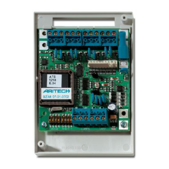
"Int./Ext. Tamp" Jumper Settings
See Figure, item 3.
•
INT: Tamper switch SW4 + switch on backside SW5 of the
PCB are used (for example, in combination with ATS1644
plastic housing).
•
EXT: Tamper connections on connector J1 (T, C) are used
for an external tamper switch (for example, in combination
with ATS1643 metal housing).
DGP dipswitch settings
ADDR (item 1): DIP switches 1 to 4 are used to identify the
DGP number.
1 / 18
P/N 1052529 • REV C • ISS 02JUL19
Advertisement
Table of Contents

Summary of Contents for United Technologies Interlogix ATS1210
- Page 1 ATS1210/1211/1220 4/8-Zone DGP Installation Sheet EN DA DE ES NL NO PL PT SV EN: Installation Sheet +12 VDC supply and open collector or data output for output connection to ATS1810, ATS1811 and ATS1820 output cards Mounting the unit via 10-way cable supplied with the output card. Up to sixteen outputs are available with 8-way or 16-way open collector The PCB can be mounted in any existing ATS series enclosure cards (4-way and 8/16-way output cards cannot be used...
-
Page 2: Specifications
ABCT (item 2): Regulatory information • T: Set switch T on if this device is the last device on the Manufacturer PLACED ON THE MARKET BY: system databus. For more details see the ATS control UTC Fire & Security Americas Corporation, Inc. 3211 Progress Drive, Lincolnton, NC, 28092, panel installation guide. - Page 3 installationsmanualen til ATS-centralenheden finder du DGP2 33–48 DGP10 161–176 detaljer. DGP3 49–64 DGP11 177–192 • TAMP T, C: Tilslut kabinetsabotagekontakten til disse DGP4 65–80 DGP12 193–208 terminaler, NO funktion. DGP5 81–96 DGP13 209–224 DGP6 97–112 DGP14 225–240 J2/J3 DGP7 113–128 DGP15 241–256 Hver zone kræver 4k7 endemodstande (1 eller 2 afhængigt af...
- Page 4 können nicht gemeinsam an derselben AME verwendet UTC Fire & Security erklærer hermed, at denne EU-direktiver enhed er i overensstemmelse med gældende werden). krav og bestemmelser i direktivet 2014/30/EU og/eller 2014/35/EU. For yderligere informationer Verbindungen se www.utcfireandsecurity.com eller www.interlogix.com. Erdungsanschluss. Alle Abschirmungen von allen 2012/19/EU (WEEE): Bortskaffelse af elektrisk og Geräten müssen geerdet werden.
- Page 5 LEDs 2012/19/EU (WEEE): Produkte die mit diesem Symbol gekennzeichnet sind, dürfen nicht als • RX: LED blinkt, um anzuzeigen, dass abgefragte Daten unsortierter städtischer Abfall in der europäischen am Systemdatenbus von der ATS-Einbruchmeldezentrale Union entsorgt werden. Für die korrekte empfangen werden. Wenn die LED nicht blinkt, ist die Wiederverwertung bringen Sie dieses Produkt zu Einbruchmeldezentrale nicht funktionsfähig, oder der Ihrem lokalen Lieferanten nach dem Kauf der...
-
Page 6: Especificaciones
sistema. Para obtener más detalles, consulte el manual de o el bus de datos está defectuoso (suele ser un problema instalación del Panel de control de ATS. de cableado). • TX: Cuando este LED parpadea, indica que el DGP está Configuración de puentes “INT/EXT TAMP”... -
Page 7: Información De Contacto
”Int./Ext. Tamp” -oikosulkupalojen 2012/19/EU (directiva WEEE): los productos marcados con este símbolo no se pueden asetukset desechar como residuos urbanos no clasificados en la Unión Europea. Para que se pueda realizar Katso kuva, kohta 3. un reciclaje adecuado, devuelva este producto a •... - Page 8 Tekniset tiedot FR: Fiche d’installation Käyttöjännite 10,5–13,8 V (12 V nom.) Montage de l’unite Maksimivirrankulutus 53 mA Mitat (korkeus x leveys) (levy kokoa B) 90 x 80 mm La carte peut être installée dans n'importe quel coffret ATS Metallikotelon mitat (korkeus x leveys x pituus) 165 x 125 x 36 mm supportant les cartes au format BB.
-
Page 9: Information Réglementaire
Information réglementaire ABCT (indice 2) : • T : Mettre le switch T sur ON s’il s’agit du premier ou du MISE SUR LE MARCHÉ PAR : Fabriquant dernier dispositif présent sur le bus de données UTC Fire & Security Americas Corporation, Inc. du système. - Page 10 • COMMS D+, D−: Connessione dati + e dati – del bus di • A, C: Non usati comunicazione del sistema. Le unità remote possono • B: ON — Al connettore J4 sono collegate schede a 8 relè trovarsi sino a 1,5 km di distanza dal concentratore per 4 ATS1811 o la scheda a 16 uscite open collector ATS1820.
- Page 11 Certificazione e conformità ATS1220 en het dichtstbijzijnde andere apparaat op de systeemdatabus. Costruttore MESSO SUL MERCATO DA: • COMMS D+, D−: Positieve en negatieve UTC Fire & Security Americas Corporation, Inc. 3211 Progress Drive, Lincolnton, NC, 28092, signaalaansluitingen van de systeemdatabus. Units kunnen maximaal 1,5 km verwijderd zijn van het 4-liften DI of het ATS-controlepaneel, afhankelijk van het gebruikte AUTORIZZATO RAPPRESENTANTE UE:...
- Page 12 Ingangsnummering Waarschuwingen DEZE PRODUCTEN ZIJN BEDOELD VOOR en disclaimers met VERKOOP AAN EN INSTALLATIE DOOR Aan een 4-ingangen DI kunnen 4 of 8 ingangen verbonden betrekking tot de GEKWALIFICEERDE BEROEPSKRACHTEN. zijn. producten UTC FIRE & SECURITY GEVEN GEEN GARANTIE DAT EEN PERSOON OF ENTITEIT Aan elk DI-adres zijn 16 ingangen toegewezen.
- Page 13 • TAMP T, C: Koble sabotasjebryteren for kapslingen over US 3 49–64 US 11 177–192 disse terminalene (Sabotasjebrytere krever normalt åpne US 4 65–80 US 12 193–208 kontakter). US 5 81–96 US 13 209–224 J2/J3 US 6 97–112 US 14 225–240 US 7 113–128...
- Page 14 Zwory Sertifisering Połączenie uziemienia. Przewody uziemiające ze wszystkich części urządzenia muszą być uziemione w jednym EU-direktiver UTC Fire & Security deklarer herved at denne punkcie uziemienia systemowego. Więcej szczegółowych enheten tilfredsstiller alle krav oppført I direktiv informacji można znaleźć w podręczniku instalacji 2014/30/EU og/eller 2014/35/EU.
-
Page 15: Instalação Da Unidade
dioda LED nie błyska, oznacza to, że centrala nie działa Informacje kontaktowe lub że magistrala systemowa jest uszkodzona (zazwyczaj www.utcfireandsecurity.com lub www.interlogix.com okablowanie). Informacje na temat pomocy technicznej można znaleźć na • TX: Dioda LED błyska wskazując, że moduł MZD stronie www.utcfssecurityproducts.pl odpowiada na odpytywanie z centrali ATS. - Page 16 Informação reguladora • EXT: Ligações do EXT Tamper no conector J1 (T, C) são utilizados para ligação de um switch de tamper externo Fabricante COLOCADO NO MERCADO POR: (ex. em conjunto com ATS1643, caixa metálica). UTC Fire & Security Americas Corporation, Inc. 3211 Progress Drive, Lincolnton, NC, 28092, USA Configurações do dipswitch do DGP REPRESENTANTE EU AUTORIZADO:...
- Page 17 DGP dipswitch-inställningar SV: Installationsanvisning ADDR (punkt 1): Dipswitcharna 1 till 4 används för att identifiera DGP-numret. Montera enheten ABCT (punkt 2): • T: Sätt på switch T om utrustningen är den sista på Kortet kan monteras i alla befintliga ATS-kortplatser som stöder B- resp.
- Page 18 Information om regler och föreskrifter SLÄPPT PÅ MARKNADEN AV: Tillverkare UTC Fire & Security Americas Corporation, Inc. 3211 Progress Drive, Lincolnton, NC, 28092, AUKTORISERAD EU-REPRESENTANT: UTC Fire & Security B.V. Kelvinstraat 7, 6003 DH Weert, Netherlands/Holland DESSA PRODUKTER ÄR AVSEDDA FÖR Produktvarningar FÖRSÄLJNING TILL OCH INSTALLATION AV och friskrivningar...
Need help?
Do you have a question about the Interlogix ATS1210 and is the answer not in the manual?
Questions and answers