
Related Manuals for Numerik Jena Kit L Series


Summary of Contents for Numerik Jena Kit L Series
- Page 1 SIMPLY PRECISE USER MANUAL KITL SERIES Optical Linear Encoder with Online Compensation...
-
Page 2: Table Of Contents
KITL-Series INDEX Features and Applications ����������������������������������������������������������������������������������������������� 4 Safety ������������������������������������������������������������������������������������������������������������������������������������ 5 2�1 General Information ���������������������������������������������������������������������������������������������������� 5 2�2 Notes on Legal Requirements ������������������������������������������������������������������������������������� 6 2�3 Notes on Transport, Storage and Handling ����������������������������������������������������������������� 7 2�4 Notes on Operation ����������������������������������������������������������������������������������������������������� 8 2�5 Notes on Maintenance ������������������������������������������������������������������������������������������������... - Page 3 KITL-Series General Installation Notes ���������������������������������������������������������������������������������������������� 29 7�1 Delivery Contents ������������������������������������������������������������������������������������������������������ 29 7�2 Installation Position ��������������������������������������������������������������������������������������������������� 29 7�3 Mounting Steps ��������������������������������������������������������������������������������������������������������� 30 Signal Adjustment with ADJUSTMENT TOOL ����������������������������������������������������������� 37 8�1 Functions of the ADJUSTMENT TOOL ��������������������������������������������������������������������� 37 8.2 Dynamic Offset and Amplitude Control (Online Compensation) ������������������������������� 37 8�3 Scope of Delivery ������������������������������������������������������������������������������������������������������...
-
Page 4: Features And Applications
• High machining speeds and therefore high accelerations make low masses of the components in motion essential� The Kit L incremental encoders from NUMERIK JENA are equipped with features which are supposed to fulfill these high requirements in an ideal way. • Due to an interpolation circuitry which is integrated in a 15-pin D-sub connector, a resolutions down to 50 nm is possible without any additional electronics�... -
Page 5: Safety
Please contact the support of NUMERIK JENA GmbH or an authorized representation for further information� Please visit the NUMERIK JENA website to get the contact information� • NUMERIK JENA GmbH is not liable for damages caused by unauthorized handling of the encoders� Any unauthorized handling leads to forfeiture of all warranty claims� •... -
Page 6: Notes On Legal Requirements
IEC 62368-1 2nd Ed�, section 6�2�2�5 PS or from a Class 2 secondary circuit as specified in UL1310.* • This user manual supersedes all previous editions, which thereby become invalid� The basis for ordering from NUMERIK JENA is always the user manual edition valid when the contract is made� • Standards (ISO, EN, etc.) apply only where explicitly stated in the user manual. In place of IEC 61010-1 , Section 9�4, the corresponding sections of standards DIN EN 61010-1, EN61010-1, UL 61010-1 and... -
Page 7: Notes On Transport, Storage And Handling
- simply pressing them together again will not result in sufficient adhesion. In this case neither the operational reliability nor the metrological properties can be guaranteed anymore. Please return the scale tape to NUMERIK JENA GmbH for repair! Unfortunately a repair at the customer site is not possible. -
Page 8: Notes On Operation
Modifications and repairs of the encoder may only be carried out by NUMERIK JENA GmbH or appropriately authorized persons� • NUMERIK JENA GmbH is not liable for damages caused by unauthorized handling of the encoder� All warranty claims are forfeited by unauthorized handling� • Exposed measuring systems are sensitive to contamination, especially the scale surface and the scanning windows for the counting and reference tracks on the scanning head�... -
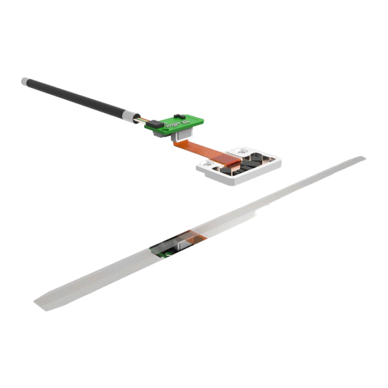
Page 9: Setup Of The Rotary Kit Encoder
KITL-Series Setup of the Rotary Kit Encoder Setup with Signal Processing in a D-Sub Connector This setup consists of the following components: • EPIFLEX sensor module glued into a very flat frame • Scale tape with incremental and index track • Connector PCB to connect flex cable with round cable of the connector • Connector with integrated electronics (1 V or RS 422) and cable EPIFLEX sensor module with Frame... -
Page 10: Setup Without Signal Processing
KITL-Series Setup without Signal Processing This setup consists of the following components: • EPIFLEX sensor module glued into a very flat frame • Scale tape with incremental and index track EPIFLEX sensor module with Frame Customers electronics Flex cable = 5 V Output signal: • 1 V • TTL (w/o interpolation) Recommended con- recommended C1 = 22 µF... -
Page 11: Features Kit L2
KITL-Series Features Kit L2 The Kit L2 encoders from NUMERIK JENA are 2-field scanning units. The advantage compared with 1-field scanning units is a lower sensitivity to contaminations. Sensor layout: EPIFLEX sensor module with Frame (example) Scanning field 1 for incremental track Scanning field for index track Scanning field 2 for incremental track Scale tape (MV) Image 5 Features Kit L4 The Kit L4 encoders from NUMERIK JENA are 1-field scanning units. The advantage compared with 2-field scanning units is a smaller frame size. Sensor layout: Scale tape (MT) EPIFLEX sensor module with Frame Scanning field for (example) incremental track... -
Page 12: Singleflex Scale Tape
KITL-Series SINGLEFLEX Scale Tape The SINGLEFLEX scale tape from NUMERIK JENA consists of a single stainless steel tape with an applied incremental track and one or more reference marks� The scale tape is equipped with a double- sided adhesive tape and can be mounted easily on the machine element�... -
Page 13: Doubleflex Scale Tape
KITL-Series DOUBLEFLEX Scale Tape The DOUBLEFLEX-scale tape consists of two superimposed steel tapes� Both of them are divided by a tension uncoupled sheen of oil which ensures the adhesion between the steel tapes� The incremental track and one or more reference marks are applied on the upper steel tape� The lower steel tape is equipped with a double-sided adhesive tape and can be mounted easily on the machine element�... -
Page 14: Technical Data
KITL-Series Technical Data Resolution and Accuracy (Definition) Basically one has to differentiate between the resolution and the accuracy of a measuring system. The two parameters are not directly interdependent and may differ from each other. Resolution The resolution of linear system describes the least possible displacement of scanning head against the scale which can still be discerned by the evaluation electronics (display, control). It depends on (see chart 1) • the graduation period of the scale • the signal intepolation factor (internally or in auxiliary electronic unit) • the evaluation mode in the counter Accuracy The accuracy of linear measuring systems is specified in accuracy classes. -
Page 15: Mechanical Data
KITL-Series Mechanical Data Kit L2 Kit L4 Dimensions of scan head 20 mm x 8 mm 13 mm x 8 mm Weight of sensor 2�5 g recommended measuring steps 0�05 µm, 0�1 µm, 0�2 µm, 0�5 µm, 1�0 µm, 5�0 µm Traversing speed Maximum 10 m/s (without interpolation) -
Page 16: Electrical Data
KITL-Series Electrical Data Kit L2 Kit L4 Scanning frequency max� 500 kHz Supply voltage 5 V ±10% Output interfaces Voltage output Square wave output TTL w/o interpolation, RS 422 with interpolation up to 100-times Current consumption Voltage output ≤90 mA* ≤80 mA* Square wave output ≤220 mA* ≤210 mA*... -
Page 17: Attainable Traversing Speed
KITL-Series Attainable Traversing Speed The maximum attainable traversing speed of the encoder is determined by the maximum output frequency of the interpolator and/or the maximum counting frequency of the operator‘s evaluation electronics� In order to avoid counting errors, the interpolator‘s output frequency is matched to the counting frequency of the operator‘s evaluation electronics�... -
Page 18: Ambient Conditions
(see also point 6�2! Extension Cable (connection cable from D-Sub connector to controller) • Use preferably original extension cables made by NUMERIK JENA� This guarantees an optimum compatibility with the encoders and ensures a maximum protection against electromagnetic interferences�... -
Page 19: Connector Pcb
KITL-Series Connector PCB 6.8.1 Type 1 with Signal Processing RS 422 with interpolation Ø 2.6 Round cable with connector Locating surface Flex cable Output X (vertical) 10.6 Locating surface Diagnose pins for signal adjustment Input X (horizontal) Flex cable 12.7 EPIFLEX sensor module : 12 pin (glued into a frame) -
Page 20: 6�8�3 Type 2 Without Signal Processing
KITL-Series 6.8.3 Type 2 without Signal Processing 10.6 15.6 Locating surface Signal processing in a D-Sub connector Flex cable Ø 2.6 Round cable with connector Locating surface Ø 5.1 12.4 Input X : 12 pin (vertical) Output X : 14 pin (horizontal) Image 14 Dimensions Connector Cable with Open Output Heat shrink tube 10/14 Ø... -
Page 21: Connector Variants
KITL-Series 6.10 Connector Variants Type Image connector Pins 15-pin D-Sub 10 11 12 13 14 15 10 11 12 13 14 15 10 11 12 13 14 15 10 11 12 13 14 15 9-pin D-Sub 12-pin round connector (Plastic-coated connector) 10 9 10 9 10 9... -
Page 22: Pin Assignment
KITL-Series 6.11 PIN Assignment 15 pin D-Sub Connector Housing Inner Outer shield shield Inner Outer RS 422 shield* shield Cable Ø 3�7 mm Cable Ø 5�1 mm wh/gy * for signal processing in the 15-pin D-sub connector 9 pin D-Sub Connector Housing Inner Outer shield* shield Outer RS 422 shield Cable Ø... -
Page 23: Pin Assignment For Connector Pcb
KITL-Series 6.12 PIN Assignment for Connector PCB X RS 422 6.13 PIN Assignment for JST Miniature Connector X and X 10 pin JST Miniature Connector Inner shield RS 422 Cable Ø 3�7 mm Cable Ø 5�1 mm wh/gn 14 pin JST Miniature Connector Inner shield RS 422 NAS SCL... -
Page 24: Electromagnetic Compatibility (Emc)
When using additional electronics, connect the housing electrically conducting to ensure good galvanic conductivity� For insulated installation the housing should be connected at the shortest distance by an additional potential equalization line (Cu line with cross section ≥6 mm ) with the machine’s protective ground� • Please contact the NUMERIK JENA support or that of the appropriate manufacturer if you experience any problems when working with specific display or control units. 24/58... -
Page 25: Shielding Concepts
KITL-Series 6.15 Shielding Concepts Kit L Image Subsequent Scanning head + PCB Subsequent electronics Scanning head + PCB electronics Inner shield Outer shield Inner shield Outer shield output Encoder cable Ø 5.1 mm 15 pin D-Sub connector = Pin 15 Encoder cable Ø... -
Page 26: Voltage Output 1 V
KITL-Series 6.16 Voltage Output 1 V Optimal Connection Circuit – – – –U 1– 2– 0– Ω = 120 Image 17 Signal Curve 360° (Signal period) 90° (Phase difference) Image 18 Difference signals measured at R = 0�6 ��� 1�2 V (Rated voltage: 1 V = 0�6 ���... -
Page 27: Square-Wave Output Rs 422
KITL-Series 6.17 Square-Wave Output RS 422 Optimal Connection Circuit RS 422 line receiver (e.g. AM 26 LS 32, MC 34 86) RS 422 line driver R = 120 Ω 1– 2– 0– Image 19 Signal Curve NAS high: 360° (Signal period) Encoder functioning properly, input signals within tolerance range 90°... -
Page 28: Online Compensation (Offset And Amplitude Control)
KITL-Series 6.18 Online Compensation (Offset and Amplitude Control) Contamination and mounting errors lead to interferences in the optical scanning of the scale by the scanning head and so to periodic deformations of the sinusoidal counting track signals, which are exemplified as •... -
Page 29: General Installation Notes
KITL-Series General Installation Notes Delivery Contents Standard • Kit L2 and Kit L4 scanning head (according to the ordered specification) • SINGLEFLEX or DOUBLEFLEX scale tape (according to the ordered specification) • Spacing gage for mounting the scanning head (made of plastic with marking „0,6“) • Information sheet Optional • ADJUSTMENT TOOL • Extension cable Installation Position • The installation position of the measuring system is arbitrary� • In order to avoid contamination deposits, a vertical position for the scale tape is recommended� •... -
Page 30: Mounting Steps
KITL-Series Mounting Steps Hereafter the mounting steps for a Kit L measuring system from NUMERIK JENA will be described� • Please read the notes mentioned to the particular mounting steps thorough and follow the indicated sequence of mounting steps exactly! •... - Page 31 KITL-Series • Use a solvent to clean the adhesion surface of the machine (e.g. Acetone or Alcohol). • Make sure that no contaminations remain on the machine‘s adhesion surface� • Alien elements between the machine and scale tape cause local differences in the spacing between the scale tape and the scanning head� This may diminish the encoder‘s functionality and/or result in measuring errors�...
- Page 32 KITL-Series • If you use a DOUBLEFLEX scale tape, glue the fixing point first. • Please pay attention to the use and safety instructions from the manufacturer of the adhesive! • Place a drop of adhesive on the center of the fixing point. • Recommended adhesives: Cyanoacrylate adhesives such as Loctite 480 or Loctite 401 Epoxy resin blue protective film for the scale (on the top) DOUBLEFLEX Scale Tape •...
- Page 33 KITL-Series • Do not remove the blue transparent protective film from the scale tape yet! • Remove the red protective film from the slot or edge. • On the DOUBLEFLEX scale tape, apply the fix point with the drop of adhesive (at either the beginning or end of the scale tape) and at the same time secure the first ca. 50 mm of the scale tape� • Place the end of the SINGLEFLEX scale tape from which the protective film has been removed against the front end stop (slot) or lateral stop (edge). blue protective film for scale tape (on the top) red protective film 33/58...
- Page 34 KITL-Series • Do not remove the blue transparent protective film from the scale tape yet! • Press the scale tape with your forefinger and by the help of a soft, lint-free rag against the carrier over the entire length. Pull off the red protective film to the side. The pressure point should always be ca� 30 mm to 50 mm behind the point where the adhesive tape and the red protective film are being separated. • Only apply pressure to the scale tape from above and avoid lateral forces! • Clean the mounting surfaces of the scanning head and the machine element� •...
- Page 35 KITL-Series • Screw the scanning head onto the prepared mounting surface such that there is still some vertical clearance� • Remove the blue transparent protective film (in case of DOUBLEFLEX scale tape, always begin at the fixing point) from the graduation of the scale tape. • Clean the scale tape surface (graduation) of the scanning head with a soft and lint-free rag. Use a solvent if necessary (e.g. Acetone or Alcohol). • ATTENTION: Acetone and Alcohol are inflammable liquids! mounting example blue protective film 35/58...
- Page 36 If there are errors in the function or during measurement, please read chapter 12 “Troubleshooting” first. If these information are not helpful for your problem, please contact the technical support of NUMERIK JENA or an authorized representation in your country�...
-
Page 37: Signal Adjustment With Adjustment Tool
KITL-Series Signal Adjustment with ADJUSTMENT TOOL Before delivery the encoders from NUMERIK JENA will be tested and electronically adjusted under ideal mounting conditions. Furthermore, the sensor modules offer the possibility of an electronic signal adjustment after the mounting into the application� This allows the user optimize the encoder signals regarding to the mechanical mounting conditions (tolerances). The ADJUSTMENT TOOL and the related EPIFLEX software was designed to simplify and make the signal adjustment more effective. -
Page 38: Epiflex Software
The EPIFLEX software is available for free via download on the NUMERIK JENA website under www.numerikjena.de. Furthermore, one can order the software with an optional USB flash drive. -
Page 39: Mounting Drawing - Kit L2
KITL-Series Mounting Drawing - Kit L2 Scanning Head Kit L2 14.5 2.75 Illustration sensor without frame and SINGLEFLEX scale tape Image 26 Scale tape H ± 0,1 Machine guideway SINGLEFLEX 1,05 mm The mounting surface must be vertically adjustable to ensure that the distance parameter H ±0�1 and the DOUBLEFLEX 1,3 mm parallelism 0�025 can be achieved... -
Page 40: Assignment Of Scanning Head, Scale Tape And Measuring Length
KITL-Series Assignment of Scanning Head, Scale Tape and Measuring Length SINGLEFLEX and DOUBLEFLEX with fixpoint at the start of ML Positive counting direction Start of ML End of ML Measuring length ML 14.5 Max. overrun Max. overrun 2.75 DOUBLEFLEX with fixpoint at the end of ML Scale tape length = ML + 30 Image 27 SINGLEFLEX without name plate... -
Page 41: Contour For Sensor Frame
KITL-Series Contour for Sensor Frame 20.5 +0.1 Adhesion point Adhesion point 0.01 0.08/50 Scale tape R: all radii = 1 Image 29 Permissible Mounting Tolerances and Position Deviations (Coordinates) φ φ EPIFLEX sensor module ΔZ = ±0.15 mm ΔY = ±0.3 mm φ φZ = ±0.15° (±9‘) φY = ±0.25° (±15‘) φX = ±2.0° (±120‘) Scale tape Gap between sensor and scale = 0�6 mm (for 20 µm grating pitch) -
Page 42: Sensor Frames - Examples
KITL-Series Sensor Frames - Examples 9.5.1 Frame B1 / B2 11.5 11.5 Image 31 9.5.2 Frame L2 / L3 Image 32 9.5.3 Frame P4 Image 33 42/58... -
Page 43: Mounting Drawing - Kit L4
KITL-Series Mounting Drawing - Kit L4 10.1 Scanning Head Kit L4 Flex cable vertical Flex cable horizontal Illustration sensor without frame and SINGLEFLEX scale tape Image 34 Scale tape H ± 0,1 Machine guideway SINGLEFLEX 1,05 mm The mounting surface must be vertically adjustable to ensure that the distance parameter H ±0�1 and the DOUBLEFLEX 1,3 mm... -
Page 44: Assignment Of Scanning Head, Scale Tape And Measuring Length
KITL-Series 10.2 Assignment of Scanning Head, Scale Tape and Measuring Length SINGLEFLEX Positive counting directon Positive counting directon ML/2 Measuring length ML Start of ML Start of ML Total length TL = ML + 14 DOUBLEFLEX ML/2 12.2 Start of ML Measuring length ML Start of ML Total length TL = ML + 18... -
Page 45: Contour For Sensor Frame
KITL-Series 10.3 Contour for Sensor Frame 0.02/20 0.01 Adhesion point 13.5 +0.1 Adhesion point R: all radii = 1 Image 36 10.4 Permissible Mounting Tolerances and Position Deviations (Coordinates) ΔZ = ±0.15 mm ΔY = ±0.3 mm φ φZ = ±0.3° (±18‘) φ φY = ±0.25° (±15‘) φX = ±2.0° (±120‘) EPIFLEX sensor module φ Gap between sensor and scale = 0�6 mm (for 20 µm grating pitch) Scale tape... -
Page 46: Sensor Frames - Examples
KITL-Series 10.5 Sensor Frames - Examples 10.5.1 Frame B1 / B2 / B3 / B4 B1 / B2 B1 / B2 with 90° Flex Cable B3 / B4 with Sensor 180° B1 = M2 B1 = M2 B3 = M2 B2 = ø... -
Page 47: Cleaning
KITL-Series Cleaning • Depending on the measuring system‘s mounting attitude and the ambient conditions, it may be necessary to clean the scale tape surface and sensor surface of the scanning head (scanning window for counting and reference track) occasionally. • If the monitoring signal output by the scanning head is used, the encoder indicates that cleaning is necessary�... -
Page 48: Troubleshooting
However, if troubles or problems should occur, please read the following points in the chart and proceed according these information� If this is not helpful, please contact the technical support of NUMERIK JENA GmbH or one of our authorized representations. You will find respective contact data on the NUMERIK JENA webside www. -
Page 49: Ordering Key
Messkopf KITL2 EN KITL2 EN KITL-Series Ordering key - example KITL – – Ordering Key Messkopf KITL2 EN Product name Connector type With JST mini. connector KITL With signal processing 10-pin., socket 13.1 Scanning Head Kit L2 With JST mini. connector Ordering key - example Without signal processing 14-pin., socket... -
Page 50: Scanning Head Kit L4
KITL4 EN Messkopf KITL4 EN KITL-Series Ordering key - example KITL – – Messkopf KITL4 EN 13.2 Scanning Head Kit L4 Connector type Product name With JST mini. connector Ordering key - example KITL With signal processing 10-pin., socket KITL –... -
Page 51: Speed Chart For Lik Series
The encoders from NUMERIK JENA are available without op-amp also� Thus it is possible to increase the scanning frequency which consequently enables higher traversing speeds up to 10 m/s�... - Page 52 KITL-Series Interpolation factor = 25 Min� counting frequency of Min� counting frequency of Max� scanning frequency of Value for Max� traversing speed the evaluation electronics the evaluation electronics the measuring system (in m/s) without 4-edge evaluation with 4-edge evaluation (in kHz) (in MHz) (in MHz) 0�13 0�25...
-
Page 53: 13�3�2 Lik Series Without Op-Amp
KITL-Series 13.3.2 LIK Series without Op-Amp The maximum scanning frequency of the encoder without op-amp amounts to 500 kHz, hence the maximum attainable traversing speed will be derived from that� This enables traversing speeds up to 10 m/s� (1 VSS) or (RS 422) Without interpolation factor Min�... - Page 54 KITL-Series Interpolation factor = 25 Min� counting frequency of Min� counting frequency of Max� scanning frequency of Value for Max� traversing speed the evaluation electronics the evaluation electronics the measuring system (in m/s) without 4-edge evaluation with 4-edge evaluation (in kHz) (in MHz) (in MHz) 0�13 0�25...
-
Page 55: Scale Tape Mv
Scale tape MV for KITL2 EN Ordering key - example KITL-Series – 00700 13.4 Product name Scale Tape MV Measuring length (ML) ML in mm Measuring standard with asymmetric reference mark for double-field sensors Ordering key - example Grating period (TP) – 00700 20 µm Material... -
Page 56: Scale Tape Mt
Scale tape MT for LIK41, KITL4 EN Ordering key - example KITL-Series – 00120 Product name Measuring length (ML) 13.5 Scale Tape MT ML in mm Measuring standard with symmetric reference mark for 1-field sensors Ordering key - example Grating period (TP) –... -
Page 57: Adjustment Tool
KITL-Series 13.6 ADJUSTMENT TOOL Name Scope of delivery / Description Order-no� • ADJUSTMENT TOOL black box • Diagnostic cable to connect the measuring system ADJUSTMENT TOOL 344220-33 • USB cable to connect a PC • USB - D-SUB - adapter cable (15-pin) • Exchangeable 8-pin plug connectors Optional Single Components Name Description... - Page 58 NUMERIK JENA GmbH Im Semmicht 4 Phone: +49 3641 4728-0 07751 Jena E-Mail: info@numerikjena.de Germany www.numerikjena.de Version 03/2021...
Need help?
Do you have a question about the Kit L Series and is the answer not in the manual?
Questions and answers