Table of Contents
Advertisement
Quick Links
LUNAd MB
Instructions for Use
Content
Introduction ....................................................... 3
1.1 Introduction .......................................................... 3
1.2 Selection of room temperature ............................. 3
1.3 LED status lamp .................................................... 3
System overview and installation. .................... 3
2.1 System overview ................................................... 3
2.2 Terminal functions ................................................ 3
2.3 Invert heating outputs ........................................... 4
2.4 Resetting .............................................................. 4
2.5 Hand-held terminal LUNAd T-CU........................... 4
Control functions ................................................ 5
3.1 Operating modes .................................................. 5
3.2 Setting room temperatures ................................... 5
3.3 Deadband ............................................................. 5
3.4 Control process ..................................................... 5
3.5 P-function ............................................................. 5
3.6 I-function .............................................................. 5
Inputs and sensors .............................................. 6
4.1.1 Sensor type ........................................................ 6
4.1.2 Average value measurement ............................... 6
4.2 Occupancy sensor ................................................. 6
4.2.1 Switch-on delay ................................................. 6
4.2.2 Switch-off delay ................................................. 6
4.2.3 Inverting the occupancy signal ........................... 6
4.3 Overriding the operating mode ............................. 6
is activated ................................................................. 6
4.4 Condensation sensor ............................................ 7
4.4.1 Select effect of output A1 .................................. 7
Outputs and actuators ....................................... 8
5.1 Actuators .............................................................. 8
5.2 Output signals ...................................................... 8
of output .................................................................... 8
5.4 Limitation of control range .................................... 9
The document was originally written in Swedish
5.7 Inverting the output .............................................. 9
5.8 Periodic valve operation ........................................ 9
Data communication......................................... 10
6.1 Modbus protocol ................................................ 10
6.1.1 Modbus RTU protocol ....................................... 10
6.1.2 Data bits and bytes .......................................... 10
6.1.3 Data rate .......................................................... 10
6.1.4 Modbus RTU protocol ...................................... 10
6.1.5 Modbus address ............................................... 10
6.1.6 Modbus register ................................................11
6.1.7 Modbus command ............................................11
6.1.8 Modbus RTU over Ethernet ................................11
6.1.9 Error messages ..................................................11
6.1.10 Delays and communication errors ................... 12
6.1.11 Monitoring program ....................................... 12
6.2 RS-485 network ................................................. 12
6.2.1 Nodes, server and clients .................................. 12
6.2.2 Transceiver ....................................................... 12
6.2.3 Bits and signal levels ........................................ 13
6.2.4 Converter ........................................................ 13
6.2.5 Repeater .......................................................... 13
6.2.6 Screw terminals for network cable ................... 13
6.2.7 Twisted pair cabling ......................................... 13
6.2.8 Galvanic isolation ............................................. 13
6.2.9 Polarisation ...................................................... 13
6.2.10 Termination .................................................... 13
6.2.11 Electromagnetic interference .......................... 14
6.2.12 Shielded cable ................................................ 14
6.3 Network structure ............................................... 14
6.3.1 Segments ......................................................... 14
6.3.2 Number of nodes ............................................. 14
6.3.3 Network cable ................................................. 14
6.3.4 Shielded cable.................................................. 15
6.3.5 Earth wire ........................................................ 15
6.3.6 Polarisation ...................................................... 16
6.3.7 End termination ............................................... 16
6.4 Network troubleshooting .................................... 16
08/04/2021
Advertisement
Table of Contents

Related Manuals for Swegon LUNAd MB

Summary of Contents for Swegon LUNAd MB
-
Page 1: Table Of Contents
LUNAd MB Instructions for Use 08/04/2021 Content Introduction ............3 5.7 Inverting the output ..........9 1.1 Introduction ............3 5.8 Periodic valve operation ........9 1.2 Selection of room temperature ......3 Data communication......... 10 1.3 LED status lamp ............ 3 6.1 Modbus protocol .......... - Page 2 7.12 Outputs, settings ..........28 7.13 Inputs, settings ..........30 7.14 Occupancy ............31 7.15 Calibration of temperature sensors..... 32 7.16 Button functions ..........33 7.17 Test menu ............34 7.18 Type designations ..........36 Swegon reserves the right to alter specifications. 08/04/2021...
-
Page 3: Introduction
10. Modbus + 2. Red = heating requirement 3. Flashing blue = condensation (only when the 11. Modbus - condensation function is active in the room controller and the operating mode is cooling requirement. 08/04/2021 Swegon reserves the right to alter specifications. -
Page 4: Invert Heating Outputs
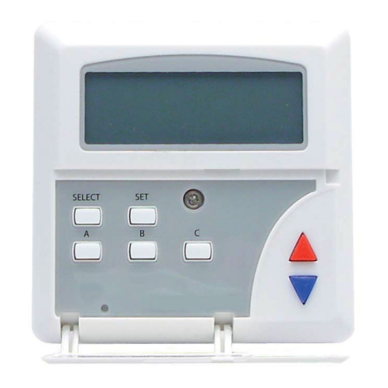
Function LED Set point potentiometer Function button All the settings are described in the manual, chapter 7 2 3 4 5 6 7 Modbus adress Connector for configuration tool Temperature H202 Sensor Swegon reserves the right to alter specifications. 08/04/2021... -
Page 5: Control Functions
If the room controller is set to only control heating or only cooling, then the deadband has not function, and the room temperature is then controlled directly to the temperature set for each operating mode. 08/04/2021 Swegon reserves the right to alter specifications. -
Page 6: Inputs And Sensors
Enabling the external contact function is selected under menu 5 with the help of the hand-held terminal LUNAd T-CU. Function “EXT.”: 0 = external contact function disabled 1 = external contact function enabled Swegon reserves the right to alter specifications. 08/04/2021... -
Page 7: Condensation Sensor
If this function is enabled, the controller activates the 10 V DC output on Y3 (terminal 4) when condensation occurs. Function “CALRM” 0 = alarm signal disabled 1 = alarm signal enabled 08/04/2021 Swegon reserves the right to alter specifications. -
Page 8: Outputs And Actuators
It is possible to set the controller so that the 0–10 V outfeed to output A1 is available both for heating and cooling requirement to control of an actuator on a 6-way valve. Swegon reserves the right to alter specifications. 08/04/2021... -
Page 9: Limitation Of Control Range
100 % of the capacity is fed to the output. When the temperature reaches “LIM.-0” or is outside of this value, 0 % of the capacity is fed to the output. 08/04/2021 Swegon reserves the right to alter specifications. -
Page 10: Data Communication
Termination of the cable ends may also be necessary at right on the dip switch should be set to the off position higher rates to eliminate reflection interference. (i.e. not “ON”). Swegon reserves the right to alter specifications. 08/04/2021... -
Page 11: Modbus Register
04. Read 16-bit status register (area 3x) 05. Write to 1-bit register (area 0x) 06. Write to 16-bit register (area 4x) 15. Write to more 1-bit registers (area 0x) 16. Write to more 16-bit registers (area 4x) 08/04/2021 Swegon reserves the right to alter specifications. -
Page 12: Delays And Communication Errors
1 km and sometimes further. All depending on how well the network is structured. Swegon reserves the right to alter specifications. 08/04/2021... -
Page 13: Bits And Signal Levels
An earth wire also needs to be connected to all nodes to terminal G0 (also called GND on some node’s screw terminals). The earth cable shall also be connected to the protective earth, usually in the vicinity of the server. 08/04/2021 Swegon reserves the right to alter specifications. -
Page 14: Termination
If you still connect the nodes via long branches, reflective interference can occur as each branch becomes a new small segment. Swegon reserves the right to alter specifications. 08/04/2021... -
Page 15: Shielded Cable
24 V supply are connected on the same terminal number on all nodes. Otherwise there is a risk of the nodes failing. 08/04/2021 Swegon reserves the right to alter specifications. -
Page 16: Polarisation
A complete Modbus packet the network. from the server should then be seen as well as the node’s response back to the server. Swegon reserves the right to alter specifications. 08/04/2021... -
Page 17: Deviations From The Modbus Standard
6.5.2 Data rate The supplied room controller model is set to communicate at 19200 bits/sec. 08/04/2021 Swegon reserves the right to alter specifications. -
Page 18: Modbus Register
1 = I2 on, terminal 7 is set (0V) 1=on 0 = occupancy dissconnected 0=off 10004 Occupancy status 1 = occupancy connected 1=on 0 = no condensation 10005 Condensation status 0 = off, 1 = on 1 = condensation Swegon reserves the right to alter specifications. 08/04/2021... -
Page 19: Area 3X
Program no. 1 (two last numbers) 0-99 30015 Program no. 1 (two first numbers) 0-99 30016 Version number 0-99 30017 Drawing no. 1 (two last numbers) 0-99 30018 Drawing no. 2 (two first numbers) 0-99 08/04/2021 Swegon reserves the right to alter specifications. -
Page 20: Area 4X
= -9,9° - +9,9°K. External room The ModBus value changes the selected calibration 40016 temperature value for the exter- nal sensor. Value -99 - +99 = -9,9° °K sensor calibration - +9,9°K. Swegon reserves the right to alter specifications. 08/04/2021... - Page 21 D2 output pulse. 5-995 = 0,5-99,5 minutes Period time for A1 The ModBus value changes the selected period time for 40038 at pulse output the A1 output pulse. 5-995 = 0,5-99,5 minutes 08/04/2021 Swegon reserves the right to alter specifications.
- Page 22 Not in use Not in use, reserved for future use Occupancy, on 40052 Occupancy, on delay in minutes. Default = 0 delay Occupancy, off 40053 Occupancy, off delay in minutes. Default = 60 delay Swegon reserves the right to alter specifications. 08/04/2021...
-
Page 23: Menu Functions With Hand-Held Terminal
The downloaded values in the tool cannot be transferred to another controller once the tool’s power has been switched off as the unit loses all data that has been downloaded. 08/04/2021 Swegon reserves the right to alter specifications. -
Page 24: Hand-Held Terminal's Different Modes
A sun or moon symbol is shown (this denotes that the tool is connected to the controller and that read mode is Activates read mode. Download all active). settings from LUNAd T-CU to LUNAd RE. Swegon reserves the right to alter specifications. 08/04/2021... -
Page 25: Display Symbols
(the middle number starts to flash) use arrow up to increase or arrow down to decrease the value. Complete the change by pressing the SET button again to leave “change value mode”. The value stops flashing. 08/04/2021 Swegon reserves the right to alter specifications. -
Page 26: Display Overview
PAR. Stopb BYTE All function values are organised in a menu system as set out above. There is 1 main menu, 11 settings menus with a number of functions under each menu. Swegon reserves the right to alter specifications. 08/04/2021... -
Page 27: Week Programme
HEAT DB.S P-band, heating “P.H”0.5 - 99.5 K P-band, cooling “P.C”0.5 - 99.5 K HEAT I-time, heating “I.H”0 - 99.5 min HEAT I-time, cooling “I.C”0 - 99.5 min HEAT 20.0 HEAT 20.0 08/04/2021 Swegon reserves the right to alter specifications. -
Page 28: Outputs, Settings
The deadband is used as soon as the controller detects that both heating and cooling outputs are being used. Swegon reserves the right to alter specifications. 08/04/2021... - Page 29 The minimum voltage limitation does not apply for the SAVE operating mode or when the output is switched off due to the condensation function. 08/04/2021 Swegon reserves the right to alter specifications.
-
Page 30: Inputs, Settings
0 = Condensation function off. 1 = Condensation function on. c) Condensation alarm If this function is enabled, the controller activates the 10 V DC output on the analogue output Y3 when condensation occurs. Swegon reserves the right to alter specifications. 08/04/2021... -
Page 31: Occupancy
This function is useful if you wish to prevent the controller from changing the operating mode from “NIGHT” when you quickly pass through a room. 08/04/2021 Swegon reserves the right to alter specifications. -
Page 32: Calibration Of Temperature Sensors
The value can be set from -9.9 to 9.9 b) External temperature sensor Calibration of the external sensor if connected to input I2. The value can be set from -9.9 to 9.9 Swegon reserves the right to alter specifications. 08/04/2021... -
Page 33: Button Functions
- SAVE operating mode set point j) Language setting Set the language: 0 = Swedish 1 = English The value is also saved in the controller the next time you connect the hand-held terminal. 08/04/2021 Swegon reserves the right to alter specifications. -
Page 34: Test Menu
2 hours or in the event of a power failure. d) Resetting The controller’s resetting functions can reset the controller’s software or all the controller’s values to the factory settings. The resetting functions are: Swegon reserves the right to alter specifications. 08/04/2021... - Page 35 View “CODEG” generates a temporary code. Note down the code and then contact Swegon to receive an access code. The access code is then entered in the display view “CODES”.
-
Page 36: Type Designations
“SER.1”. The digits to the far right are singular and are followed by ten, hundred and thousand. The digits in the menu “SER.2” are, from right to left, ten thousand, hundred thousand, million and ten millions. Swegon reserves the right to alter specifications. 08/04/2021...
Need help?
Do you have a question about the LUNAd MB and is the answer not in the manual?
Questions and answers