
Subscribe to Our Youtube Channel
Summary of Contents for GRUNDFOS ALLDOS Conex DIA-1
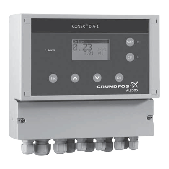
- Page 1 GRUNDFOS ALLDOS INSTRUCTIONS ® Conex DIA-1 Instrument amplifier and controller Installation and operating instructions...
- Page 2 Declaration of Conformity We Grundfos Alldos declare under our sole responsibility that the product ® Conex DIA-1, to which this declaration relates, is in conformity with the Council Directives on the approximation of the laws of the EC Member States relating to –...
-
Page 3: Table Of Contents
CONTENTS Warning Page These complete installation and Symbols used in this document operating instructions are also available on www.Grundfosalldos.com. A few words in advance Prior to installation, read these Installation data installation and operating instructions. Installation sketch Installation and operation must comply Instrument settings with local regulations and accepted General information... -
Page 4: A Few Words In Advance
Please fill in the data below after Advanced with 1 input) multipurpose measuring commissioning. It will help you and amplifier and controller you have just purchased your Grundfos Alldos service partner Note uses the company’s leading-edge measuring make subsequent adjustments to the technology. -
Page 5: Installation Sketch
4. Installation sketch... -
Page 6: Instrument Settings
5. Instrument settings General settings Control of cleaning motor Dosing time monitoring (with measuring cell type AQC-D1) Yes:_ No:_ Yes:_ No:_ Maximum dosing time at constant load of 100 % of Sample-water deficiency sensor dosing capacity On:_ Off:_ sec. Parameter settings Chlorine Peracetic Chlorine... - Page 7 Controllers Controller settings Controller parameters Min. pulse width Relay 1 Relay 2 Proportional band (3-pos. crtl.) Switching controller On:_ On:_ sec. Off:_ Off:_ Switching direction Reset time TN Constant load Downward/upward violation (PI/PID-control) (two-pos.-/cont. controller) Limit contact Downwd. Downwd. sec. Upwd.
-
Page 8: General Information
Warning subjected to mechanical loading. Caution Other applications are not approved Check that all settings are correct and not permitted. Grundfos Alldos before starting up the device! cannot be held liable for any damage resulting from incorrect use. -
Page 9: Identification
9. Identification 9.1 Nameplate DIA-1, 1-P/R/D/HP/PA/F, W-G 350-2200-10001 S/N: 08/12345 Conex DIA-1 230/240V 50/60Hz, 15 VA, IP 65 96622359P1108120808565 ® Fig. 1 Nameplate, Conex DIA-1 Pos. Description Type designation Model Product name Voltage [V] Frequency [Hz] Product number Country of origin Year and week of production Marks of approval, CE mark, etc. -
Page 10: Controllers
® 9.2 Type key, Conex DIA-1 controllers Type key example: DIA-1, 1-P/R/D/HP/PA/F, W-G Example: 1-P/R/D/HP/PA/F Measuring amplifier and controller DIA-1 Dosing Instrumentation Advanced with 1 input Input parameter 1 Redox (ORP) Chlorine (Cl ), chlorine dioxide (ClO ) or ozone (O Hydrogen peroxide (H Peracetic acid (PAA) –... - Page 11 Example: -PT -PCB -QS Disinfection electrodes Gold Platinum No disinfection measuring Other electrodes pH, ceramic diaphragm, incl. buffer solution pH, PTFE diaphragm, incl. buffer solution pH, KCl filling, incl. buffer solution pH, gel filling incl. buffer solution pH, ceramic diaphragm, excl. buffer solution pH, PTFE diaphragm, excl.
-
Page 12: Technical Data
10. Technical data 10.3 Electronic data and functions 10.3.1 Electronics 10.1 Design / enclosure class Electronics 16-bit microprocessor Wall-mounted High-resolution graphics LCD enclosure Display IP65 with background light including built-in potentiostat 1 alarm relay, 2 controller Potential-free relay relays (250 V/6 A, maximum Control panel outputs 550 VA) -
Page 13: Measuring Ranges
10.3.3 Controller functions 1 to 100 seconds (only with Limit contact, two-position Interpulse period interpulse period controller) controller (P, PI, PID), three- Control functions position step controller (PI), 1 to 180 pulses per minute Maximum pulse continuous controller (only with pulse frequency frequency (P, PI, PID) controller) -
Page 14: Dimensions
10.5 Dimensions Ø 4.5 ® Fig. 2 Wall-mounted enclosure Conex DIA-1 ® Fig. 3 Control panel enclosure Conex DIA-1... -
Page 15: Installation
11. Installation 11.4 Installation in control panel 11.1 Transport and storage > 20 • Transport the device carefully, do not drop! • Store at dry and cool location. +0.8 11.2 Unpacking +0.8 1. Check the device for damage. Install as soon as possible after unpacking. >... -
Page 16: Installation Of Wall-Mounted Enclosure
11.5 Installation of wall-mounted enclosure Warning Switch off the power supply before installing! Enclosure class IP65 is only guaranteed if the terminal cover is correctly sealed, if the front panel of the terminal enclosure is closed and the appropriate cable glands or dummy caps fitted. -
Page 17: Commissioning / Electrical Connections
12. Commissioning / electrical 1. Remove the terminal cover on the front of the device. connections 2. Use the appropriate cable feedthroughs and tighten the screws carefully. Warning 3. Connect the cables used to the terminals Switch off the power supply before ®... -
Page 18: Terminals
12.1 Terminals ® 12.1.1 Wall-mounted enclosure Conex DIA-1 Fig. 8 Terminals of wall-mounted enclosure... - Page 19 ® 12.1.2 Control panel enclosure Conex DIA-1 Fig. 9 Terminals of control panel enclosure...
-
Page 20: Power Supply Connection
Legend of terminals 4. Connect phase (L1) (or the + conductor with 24 V version) to terminal 1 (wall-mounted enclosure) or 8/3 (control panel enclosure). Pos. Description Switch the device on and off by switching the power Relays Relay 1 + 2 supply on and off accordingly. -
Page 21: Current Output
12.4 Current output Output 4: continuous control This current output shows the calculated actuating Make sure that the polarity of the variable signal as an analog current signal. current output is correct! Caution Use of actuating variable signal: Maximum load: 500 . •... -
Page 22: Connection Of Measuring Cells
12.6 Connection of measuring cells 37 38 39 40 41 42 Jumper setting • All measuring values except for peroxide: All cell types: position 1 (standard). • Measuring value peroxide: Cell type HP (peroxide): position 1 (standard). • Measuring value peroxide: Cell types AQC-D1/AQC-D3: position 2 (move the wire strap of the jumper (blue) to the higher position). - Page 23 Connecting the sensor interface to the ® Conex DIA-1 (see back side of device) • Measuring cells AQC-D1/AQC-D2/AQC-D3, PA (peracetic acid) / HP (peroxide) Connect terminals 4/1 to 4/14 of the sensor interface to the corresponding terminals of the ® Conex DIA-1.
-
Page 24: Operation
13. Operation 13.1 Control and display elements 7 8 1 6 5 4 Fig. 19 Wall-mounted enclosure and control panel enclosure Pos. Description Pos. Description [Man] button Control elements • Switches between automatic and manual modes. Red alarm LED • Flashes in case of faults or incorrect –... -
Page 25: Display Elements During Initial Commissioning
13.2 Display elements during initial chlorine commissioning When connected to the power supply on the device’s initial commissioning and following the start-up 0.43 mg/l indication, the display shows the "Sprache/language" menu. Language/Langue... • After selecting and confirming the operating Deutsch language by pressing [OK] during initial commissioning, the display shows "chlorine"... -
Page 26: Software Overview
13.3 Software overview Setup "F" (full rights) Provided that the code numbers for • Selecting language access right have been set, some • Parameters: selecting measured values menus (and submenus) as well as the • Selecting measuring cell functions Cal and Man are protected Note against unauthorised access. -
Page 27: Main Menu
13.4 Main menu 1. Switch to "main menu" by pressing [OK] or, if necessary, by pressing [Esc] several times. Options in "main menu" main menu controller alarm service setup • "controller" In this submenu, a controller can be parameterised. This option will only be displayed if a type of controller has been selected in the "setup"... -
Page 28: Setup
13.5 Setup The "setup" menu can only be accessed by persons having full rights. All standard settings of the device can be defined in See section 13.5.7 Code function. the "setup" menu. During initial commissioning, basic functions are configured which after that should only Enter the code number. - Page 29 1. Select the line "parameter" using the [Up] and 13.5.3 Selection of measuring cell [Down] buttons, and press [OK] to switch to the The "measuring cell" submenu is corresponding menu. shown only if the measured values 2. Select the line(s) indicating the values to be chlorine, chlorine dioxide, ozone or Note measured (parameters) using the [Up] and...
- Page 30 13.5.4 Setting the measuring ranges for chlorine, 13.5.6 Setting the current time (date/time/summer chlorine dioxide, ozone, peroxide, time) peracetic acid, pH, redox and fluoride 1. Switch from the "setup" menu to the "date/time" In the "measuring ranges" menu, the corresponding menu.
- Page 31 The owner of full rights may do the following: 13.5.9 Adjusting display contrast • alter calibration data In the "display" menu, the contrast of the display can be adjusted. • alter setup 1. Switch from the "setup" menu to the "display" •...
- Page 32 General factory settings • Current outputs: 0-20 mA. ® • Language: The Conex DIA-1 is waiting for • With free adjustment of limits: language input. The languages "Deutsch/English – lower limit = lower end of measuring range Français.." are indicated alternately. –...
- Page 33 13.5.12 Current outputs 2. Enter the associated lower current limit using the [Up] button. Press [OK] to confirm. Make sure that the selected output – Another query for the upper limit of the corresponds with the selected Note measuring range that reads "20.00 mg/l" is parameter.
-
Page 34: Selection, Configuration And Parameterisation Of The Controller
13.6 Selection, configuration and parameterisation of the controller It takes two steps to set up the controller: • First: selection and configuration of the controller type in the "setup" menu, "controller" submenu. • Secondly: parameterisation of the selected controller type in "main menu", "controller" submenu. - Page 35 13.6.2 Selection and configuration of a switching 13.6.3 Selection and configuration of the controller continuous controller 1. Select the line "switching ctrl." using the [Up] and The continuous controller can always be used. [Down] buttons, and press [OK] to change to the 1.
- Page 36 13.6.4 Setting the controller parameters The "controller" option in "main menu" 1. Select a controller in the "setup" menu and is only available if a controller has been configure it. selected in the "setup" menu! See section 13.6 Selection, configuration and Example: Note parameterisation of the...
- Page 37 13.6.5 Controller control fields on the display • The control fields for relays 1 and 2 are displayed if a limit contact / two-position controller has been configured: chlorine Unfilled field for relay off: 0.43 mg/l Filled field (displayed inversely) for relay on: 5.20 pH 22 °C •...
- Page 38 13.6.6 Adaptation The adaptation may be aborted in the following cases: An adaptation can be started to simplify the setting of the controller parameters. • If an error message was shown during the adaptation. The adaptation is only available for PI and PID controllers.
-
Page 39: Alarm" Menu
13.7 "Alarm" menu • The alarm relay is activated after the selected alarm delay time. With the help of the alarm function, the measured • When the cause of the alarm has been removed, value can be monitored and compared with the the relay is deactivated immediately (without permitted range. - Page 40 Setting the alarm values 8. Press [OK] to return to the "alarm values" menu. 1. Select the line "alarm values" using the [Up] and 9. Select the line "alarm delay" in the "alarm values" [Down] buttons. Press [OK] to switch to the "alarm menu, and press [OK] in the corresponding on/alarm off"...
-
Page 41: Checking The Settings In The "Service" Menu
13.8 Checking the settings in the "service" menu In the "service" menu, the operator can check all important settings and test the functions of the device in the event of problems that make service necessary. In the "service" menu, calibration data and controller settings cannot be Note altered. - Page 42 Notes to figures in fig. 29: Under "water sensor" the following data are displayed: "cal temp." will only be displayed if • speed of the water sensor during the last temperature measurement or temperature calibration compensation has been switched on in the •...
-
Page 43: Calibration
13.9 Calibration 1. Press [Cal] to switch to the calibration menu. – The LED next to [Cal] illuminates. 2. Depending on the set access rights, it may be necessary to enter the four-digit code number using the [Up] and [Down] buttons. 3. - Page 44 The pH calibration is carried out as a two-point 5. Select one of the three optional buffer values calibration. offered for the buffer solutions GRUNDFOS or DIN/NIST. 6. Fill buffer 1 from the storage bottle into a clean calibration cup. cal.
- Page 45 Error messages during the reading in of the Cal. cycle voltage signal of the pH electrode • Following selection of "cal. cycle" in the The calibration may be aborted in the following "measured value" menu, a countdown function is cases: started which triggers the alarm signal "calibrate sensor"...
- Page 46 Having switched to the calibration function by 3. Enter a reference value (for example determined pressing [Cal], the display is in the mode "measured photometrically with the Grundfos Alldos DIT value" and indicates the current measured value. photometer). 1. Press [OK] to switch to the calibration menu (the 4.
- Page 47 13.9.3 Calibration of fluoride measurement Standard solution 1 In principle, the calibration of a fluoride single-rod 1. Fill the first standard solution into a clean measuring chain can be compared with the calibration cup, and dip the cleaned electrode into calibration routine of a pH electrode.
- Page 48 Error messages during the reading in of the Photometrically determined reference value voltage signal of the fluoride electrode The signal generated by the fluoride single-rod The calibration may be aborted in the following measuring chain is strongly influenced by the cases: composition of the sample water.
-
Page 49: Manual Operation
13.10 Manual operation The manual operation mode is used to switch off the automatic control and run the control relays manually. Manual operation is only possible after a controller has been configured. Note Manual operation can only be accessed with calibration rights or full rights. 1. - Page 50 13.10.1 Manual operation with configured two-position and continuous controllers "Man" controller manual dosing flow relay 1/2 stop operation 0-100 % cont. dosing flow controller 0-100 % Fig. 32 Manual operation with configured two-position and continuous controllers With configured two-position controllers, the relay –...
- Page 51 13.10.2 Manual operation with configured limit contact and continuous controller "Man" manual controller relay 1/2 operation stop cont. controller dosing flow 0-100 % Fig. 33 Manual operation with configured limit contact and continuous controller Manual operation with configured limit contacts is largely similar to manual operation with two-position controllers.
- Page 52 13.10.3 Manual operation with configured three-position step controller "Man" open controller manual close motor 3-pos. ctrl. stop operation stop Fig. 34 Manual operation with configured three-position step controller With configured three-position step controllers, the – Since switching to manual operation will cause final control element (for example the servo motor of all controllers to be switched off, none of the a dosing pump) can be manually opened or closed...
-
Page 53: Fault Finding
Repairs can only be carried out in the factory by authorised personnel. 1. Use appropriate private waste collection services. 2. If this is not possible, contact the nearest Grundfos or Grundfos Alldos company or service workshop. Subject to alterations. - Page 54 Argentina China Germany Bombas GRUNDFOS de Argentina S.A. Grundfos Alldos Grundfos Alldos Ruta Panamericana km. 37.500 Lote 34A Dosing & Disinfection Dosing & Disinfection 1619 - Garin ALLDOS (Shanghai) Water Technology Co. ALLDOS Eichler GmbH Pcia. de Buenos Aires Ltd.
- Page 55 United Arab Emirates Telefax: +52-81-8144 4010 GRUNDFOS PUMPEN VERTRIEB GRUNDFOS Gulf Distribution Netherlands Ges.m.b.H., P.O. Box 16768 Grundfos Alldos Podružnica Ljubljana Jebel Ali Free Zone Dosing & Disinfection Blatnica 1, SI-1236 Trzin Dubai ALLDOS BV Phone: +386 01 568 0610...
- Page 56 Being responsible is our foundation Thinking ahead makes it possible Innovation is the essence 15.730011 V5.0 Repl. 15.730011 V4.0 91834770 0309 www.grundfosalldos.com...
Need help?
Do you have a question about the Conex DIA-1 and is the answer not in the manual?
Questions and answers