
Related Manuals for Crumar D9U

Summary of Contents for Crumar D9U
- Page 1 DRAWBAR CONTROLLER D9U An open-source Do-it-yourself project based on Arduino. MOUNTING INSTRUCTIONS...
-
Page 2: Required Tools
Welcome to the mounting instruction sheet for the Crumar D9U Drawbar Controller kit. To assemble this kit correctly and set it up to work properly, a certain skill with electronics and computers is required, plus some tools and a little bit of patience and attention. - Page 3 Electronic parts Mechanical parts...
- Page 4 STEP 1: Let's start from the electronics. All passive components, first, starting from the lowest till the tallest. Take the four resistors, bend the terminals 90 degrees and add them to the Main PCB as shown in the pictures below. Also add the LEDs, pay attention to the polarity and the posisions.
- Page 5 STEP 2: Add the angled tactile switch and the mini TRS Jack. STEP 3: turn the PCB upside down and add the 2x8 DIL strip, as shown in the following picture. Pay attention to have it set straight on the board or you'll have troubles when coupling this board with the drawbar board.
- Page 6 STEP 4: Take the CPU board and solder the SIL terminals to the tiny board. This board contains active SMT electronics and is subject to ESD and overheat, make sure that your soldering iron doesn't exceed °C (~660°F) and don't keep the soldering pin on the terminals for too long. The SIL strip must face the bottom of the board, thus the pins will be soldered on the top side, as shown in the picture below.
- Page 7 STEP 6: Once soldered the CPU board, the final assembly should look like the picture below. Now take your cutters and cut the exceeding terminal strip leads on the JACK side, as shown below. Optionally, you can also cut the exceeding leads on the other side.
- Page 8 STEP 7: Couple the two boards. The two M3X16 black screws must be set to the right side of the drawbar board as shown here below. Then, insert the spacers on the other side, add the main board and fix the bolts using your fingers to hold the bolts and a screwdriver to tighten the screws.
- Page 9 STEP 8: Use 18 out of the 22 M3X4 black screws to fix the drawbars to the metal bottom piece, as shown in the picture sequence below.
- Page 10 STEP 9: Fix the PCB assembly to the drawbars and solder the DIL terminals. Slide the boards slighly angled so the MicroUSB connector can easily pass through the hole in the metal panel. STEP 10: Solder all drawbar terminals and the DIL strip.
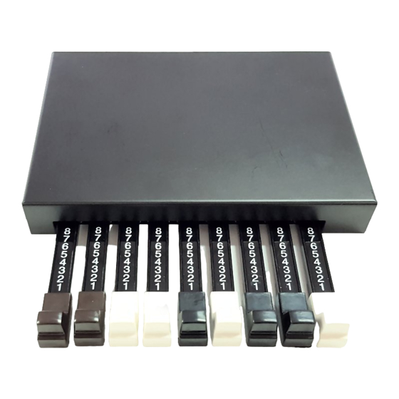
- Page 11 STEP 11: Add the plastic drawbar caps. First set them in position using the following color sequence: BROWN – BROWN – WHITE – WHITE – BLACK – WHITE – BLACK – BLACK- WHITE Once done, turn the whole assembly upside down and fix them using the 9 M3X6 screws.
- Page 12 STEP 12: Put the metal top cover. In order to have the jack connector easily pass through the hole in the metal panel, start from an angle from the connector's side. Use the remaining 4 M3X4 screws to close the cover.
- Page 13 Arduino documentation. If you haven't downloaded it yet, go to www.Crumar.it and download the Arduino sketch for the D9U from the Support section. Below the complete sketch listing with comments. //////////////////////////////////////////////////////////////////// // Crumar Drawbar Controller D9U...
- Page 14 // Called then the pushbutton is depressed void set_mode() digitalWrite(LED_RED, mode ? LOW : HIGH); digitalWrite(LED_GREEN, mode ? HIGH : LOW); EEPROM.write(0x01, mode); // Called to generate the MIDI CC message void SendMidiCC(int channel, int num, int value) midiEventPacket_t CC = {0x0B, 0xB0 | channel, num, value}; MidiUSB.sendMIDI(CC);...
- Page 15 PLEASE NOTE: before compiling the sketch, make sure you have installed the required libraries (see next chapter). Connect the D9U to your comptuer using the provided USB cable, start the IDE, load the sketch, then: 1. From the TOOLS menu, select BOARD -> Arduino Leonardo;...
- Page 16 THE ARDUINO SKETCH EXPLAINED The Atmel Atmega32U4 processor used on the Arduino Leonardo (or Pro Micro) board has 9 built-in ADC inputs (Analog-to-digital converters), just what we need to read 9 linear 10K potentiometers, that in our case are the drawbars.
-
Page 17: Schematic Diagram
USING THE OPTIONAL SERIAL MIDI OUTPUT The D9U can also be used with traditional MIDI devices that use the common DIN5 connector, but needs a special "MiniJack to DIN5" adapter. This kind of MIDI connection has become a standard in the recent years, but there are two types.
Need help?
Do you have a question about the D9U and is the answer not in the manual?
Questions and answers