Advertisement
Quick Links
PRV Switchboard Manual Section 2 - Teraski Residual Current Device Installation Instructions Vendor Manual
1. PREPARATION
DANGER :
Electrical shock or burn hazard.
Installation of this DINLINE Surge Filter should
only be made by qualified personnel. Failure
to lockout electrical power during installation or
maintenance can result in fatal electrocution or severe
burns. Before making any connections to the electrical
panel be sure that power has been removed from all
associated
wiring,
electrical
electrical equipment.
CAUTION NOTES :
1. Check to make sure line voltage does not exceed
Surge Filter voltage requirement.
2. Prior to installation ensure that the DSF is of the
correct voltage, current, and frequency rating for
your application.
3. The earth terminal must be connected to a low
impedance
earth
(<
operation.
4. Do not perform a "Flash Test" or use a Mega-Ohm
Meter (Megger) to test circuits that are protected
with DSF modules. Damage may occur to the DSF
modules.
5. Follow all instructions to ensure correct and safe
operation.
6. Do not attempt to open or tamper with the DSF
units in any way as this may compromise
performance and will void warranty.
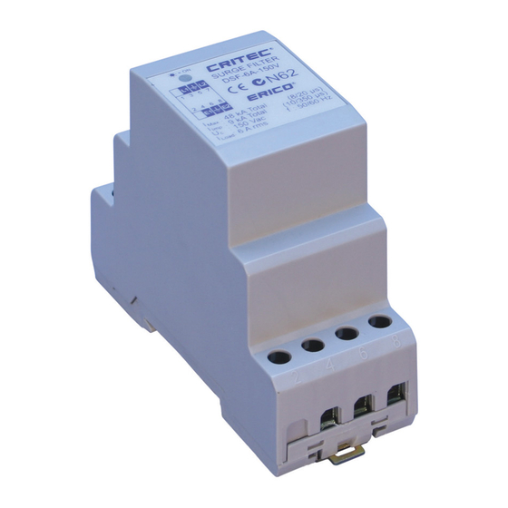
2. INTRODUCTION
Dinline Surge Filters (DSF) are packaged in "DIN 43
880" profile enclosures for simple installation onto
35mm DIN rails. They can be selected for use on
distribution systems with maximum RMS voltages of
30V, 75V, 150V or 275V at frequencies of 50/60Hz.
For applications were the voltage regulation on site is
poor, refer to the Transient Discriminating Filter (TDF)
product range.
www.erico.com
Q-Pulse Id: VM77
INSTALLATION INSTRUCTIONS
panels,
and
other
10
ohms)
for
correct
12/11/2012
DINLINE SURGE FILTER
MODEL NUMBER
DSF-6A-30V
DSF-6A-75V
DSF-6A-150V
DSF-6A-275V
DSF-10A-150V
DSF-20A-150V
DSF-10A-275V
DSF-20A-275V
3. QUICK INSTALLATION OVERVIEW
Install in the following manner:
1.
Ensure that power is removed from the area and
the circuits that will be connected.
2.
Snap lock the DSF module to the DIN rail.
3.
Install the appropriate upstream overcurrent
protection (refer to Section 8)
4.
Connect wiring to the indicated input and output
terminals.
5.
Apply power and observe correct operation of
the Status Indication LED.
4. PROTECTION CONCEPTS
To optimise effectiveness of the DSF protection, the
unprotected and protected wiring should be separated.
Wiring from the exposed transient source to the DSF
should
be
considered
approximately 300mm from all other wiring wherever
possible. Wiring on the equipment side of the DSF
should be considered protected.
The separation of protected and unprotected wiring is
recommended to minimize the risk that transients
conducted on unprotected wiring may cross couple onto
protected circuits, and diminish the level of protection
available from the DSF module.
The terminals on the DSF module are labeled
"INPUT/LINE" (unprotected side) and "OUTPUT/LOAD"
(protected side) assuming that the source of the
transients is on the input side of the DSF module.
For applications where the transient source is on the
load side of the DSF module, the DSF should be
reverse connected with the INPUT/LINE terminals
connected to the load side, toward the source of the
transients.
NOTE: The terminals on the DSF-6A modules are
labeled "L1", "L2" (unprotected side) and "E1", "E2"
(protected side). For DC systems the polarity of L1/E1
connections may be either positive or negative with
respect to L2/E2. For single phase AC systems with
neutral it is recommended to use L1/E1 for the
"hot"/phase/line conductors and L2/E2 terminals for
the neutral conductors.
Page 1 of 2
unprotected
and
kept
Page 1 of 2
Advertisement

Related Manuals for ERICO DSF-6A-30V

Summary of Contents for ERICO DSF-6A-30V
- Page 1 PRV Switchboard Manual Section 2 - Teraski Residual Current Device Installation Instructions Vendor Manual DINLINE SURGE FILTER INSTALLATION INSTRUCTIONS MODEL NUMBER DSF-6A-30V DSF-6A-75V DSF-6A-150V DSF-6A-275V DSF-10A-150V DSF-20A-150V DSF-10A-275V DSF-20A-275V 1. PREPARATION 3. QUICK INSTALLATION OVERVIEW Install in the following manner: DANGER : Electrical shock or burn hazard.
- Page 2 Customers should contact their nearest 8. FUSING AND ISOLATION Overcurrent protection must be installed in the ERICO Lightning Technologies agent to obtain a Product upstream circuit of every DSF to provide protection to Repair Authorisation Number prior to making any claim under this warranty.
Need help?
Do you have a question about the DSF-6A-30V and is the answer not in the manual?
Questions and answers