
Summary of Contents for Pleora Technologies iPORT Analog-Pro IP Engine
- Page 1 PLEORA TECHNOLOGIES INC. iPORT Analog-Pro IP Engine User Guide Installing, Uninstalling, and Starting the Software Applications...
- Page 2 These products are not intended for use in life support appliances, devices, or systems where malfunction of these products can reasonably be expected to result in personal injury. Pleora Technologies Inc. (Pleora) customers using or selling these products for use in such applications do so at their own risk and agree to indemnify Pleora for any damages resulting from such improper use or sale.
-
Page 3: Table Of Contents
Analog-Pro IP Engine Connections ........ -
Page 5: About This Guide
Chapter 1 About this Guide This chapter describes the purpose and scope of this guide and provides a list of complimentary guides. The following topics are covered in this chapter: • “What this Guide Provides” on page 2 • “Related Documents” on page 2 About this Guide... -
Page 6: What This Guide Provides
What this Guide Provides This guide provides you with the information you need to connect the iPORT Analog-Pro IP engine. In this guide you can find a product overview, instructions for connecting the IP engine cables, installing the Pleora eBUS ™... -
Page 7: About The Iport Analog-Pro Ip Engine
About the iPORT Analog-Pro IP Engine This chapter describes the IP engine, including the product variants and key features. The following topics are covered in this chapter: • “The iPORT Analog-Pro IP Engine” on page 4 • “Model Variants” on page 5 •... -
Page 8: The Iport Analog-Pro Ip Engine
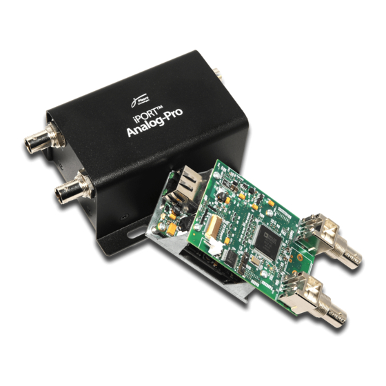
Product Formats: Board Set and Enclosed Unit The iPORT Analog-Pro IP engine is available as either a compact board set designed for use in a variety of housings, or as an enclosed unit, in a compact and rugged case that can be used in a variety of applications as a stand-alone component within a simple point-to-point GigE network, or as part of a larger switched GigE network. -
Page 9: Model Variants
Model Variants The iPORT Analog-Pro IP engine is supplied in these variants and is equipped with these parts, as listed in the following table. Table 1: Model Variants iPORT Analog-Pro IP engine package variants* iPORT Analog-Pro OEM Kit Quantity iPORT Analog-Pro Board Set... -
Page 10: Feature Set
Feature Set The iPORT Analog-Pro IP engine provides the features and functions listed in the following table. Table 2: iPORT Analog-Pro IP Engine Feature Summary Key features NTSC, PAL, CCIR, and RS-170 video signal support Full resolution and frame rate for each supported video format... -
Page 11: Selected Genicam Features
Deinterlacing Performs Line Duplication or Weaving. After you change the InputVideoFormat, Interlaced, and Deinterlacing features, you may need to adjust the Width, Height, or image offset (as the settings may now be invalid). About the iPORT Analog-Pro IP Engine... -
Page 12: Hardware Deinterlacing
2 and 4, respectively. There is a loss of vertical resolution associated with this deinterlacing method and it can introduce the video artifact referred to as “bobbing”. This method is suitable for images with larger amounts of motion. iPORT Analog-Pro IP Engine User Guide... -
Page 13: Iport Analog-Pro Ip Engine Connections
Chapter 3 iPORT Analog-Pro IP Engine Connections This chapter describes the IP engine connections. It also includes pinouts for the power, GPIO and serial connectors. The following topics are covered in this chapter: • “Connector Locations” on page 10 •... -
Page 14: Connector Locations
Main board RJ-45 Ethernet Interfaces the IP engine to Ethernet networks, as specified in connector IEEE 802.3. The Ethernet interface can operate at 10, 100, or 1000 Mbps, and supports Internet Protocol Version 4 (IPv4). iPORT Analog-Pro IP Engine User Guide... -
Page 15: Making Gpio And Serial Connections
12-pin connector Adapter board To mount the GPIO and serial connector to an enclosure backplate Insert the 12-pin connector through the external side of the backplate. Secure with washer and hex nut. iPORT Analog-Pro IP Engine Connections... - Page 16 Arrow Arrow Tab location marker marker (approximate) Adapter board and 12-pin female connector (assembled) 12-pin female connector Adapter board (unassembled) Solder the pins of the connector to the adapter board for a secure connection. iPORT Analog-Pro IP Engine User Guide...
-
Page 17: Gpio And Serial Connector Pinouts - Adapter Board
Line7 is mapped to GPIO_OUT3, which is only exposed on connector J6 (20-pin FFC connector). For information about configuring the IP engine with GEVPlayer, see “Connecting to the iPORT Analog-Pro IP Engine and Configuring General Settings” on page 27. iPORT Analog-Pro IP Engine Connections... -
Page 18: Gpio And Serial Connector Pinouts - Daughter Card
Input GPIO_OUT0 GPIO Output GPIO_IN1 GPIO Input GPIO_OUT1 GPIO Output GPIO_IN2 GPIO Input GPIO_OUT2 GPIO Output GPIO_IN3 GPIO Input GPIO_OUT3 GPIO Output No connect No connect RS232_TX0 RS-232 Output RS232_RX0 RS-232 Input Ground Ground iPORT Analog-Pro IP Engine User Guide... -
Page 19: Power Pinouts
Power Pinouts — Board Set The pinouts of the 2-pin header (J7 on the daughter card) are listed in the following table. Table 7: Power Connector Pinout Descriptions — Board Set Name Daughter card Pin 1 Pin 2 iPORT Analog-Pro IP Engine Connections... - Page 20 The mating connector is a Hirose 6-pin connector, part number HR10A-7P-6S(73). Table 8: Power Connector Pinout Descriptions — Enclosed IP Engine Name 5V to 16V regulated 5V to 16V regulated 5V to 16V regulated Ground Ground Ground iPORT Analog-Pro IP Engine User Guide...
-
Page 21: Status Leds
Chapter 4 Status LEDs The status LEDs indicate the operating status of the IP engine’s network connection and firmware. The following figure and table describe the status LEDs. Main board Network connection speed LED (J1) Network activity LED (J1) Power and firmware status LEDs (D2) Status LEDs... - Page 22 IP engine to use the backup firmware load.* *For information about the slide switches that are used to specify the firmware load, see “Changing to the Backup Firmware Load” on page 50. iPORT Analog-Pro IP Engine User Guide...
-
Page 23: Installing The Sdk
Chapter 5 Installing the SDK This chapter describes how to install the eBUS SDK, and also provides information about installing the drivers that are best suited for your system. Before you can configure and control your GigE Vision camera, you must install the eBUS SDK and driver. The following topics are covered in this chapter: •... -
Page 24: Installing The Ebus Sdk
IP engine. The Pleora Technologies eBUS SDK contains an extensive library of sample applications, with source code, to create working applications for device configuration and control, image and data acquisition, and image display and diagnostics. -
Page 25: Installing The Driver And Configuring The Nic
Optimal (limited to particular Intel® NICs) To start the Driver Installation Tool and install an eBUS driver Click Start, point to All Programs > Pleora Technologies Inc > eBUS SDK > Tools, right-click Driver Installation Tool and then click Run as administrator. - Page 26 In the Windows Control Panel, click Network and Internet. The instructions in this procedure are based on the Windows 7 operating system. The steps may vary depending on your computer’s operating system. Click Network and Sharing Center. iPORT Analog-Pro IP Engine User Guide...
- Page 27 In the left-hand panel, click Change adapter settings. Right-click the NIC and then click Properties. Click Internet Protocol Version 4 (TCP/IPv4) and then click Properties. Installing the SDK...
- Page 28 Static IP addressing allows for quicker detection and connection times on networks without a DHCP server, as the NIC does not have to negotiate a Link-Local Address (LLA). Close the open dialog boxes to apply the changes. iPORT Analog-Pro IP Engine User Guide...
- Page 29 Additionally, certain default settings on the NIC may not be appropriate for receiving high-throughput image streams, such as the number of Rx Descriptors. Refer to the Network Adapters Knowledge Base Technical Note, available at the Pleora Technologies Support Center. Installing the SDK...
-
Page 31: Connecting To The Iport Analog-Pro Ip Engine And Configuring General Settings
The GEVPlayer application is documented in the GEVPlayer Quick Start Guide and the GEVPlayer User Guide. The iPORT Analog-Pro IP Engine User Guide provides you with the GEVPlayer instructions and overviews required to set up and configure the IP engine. -
Page 32: Connecting The Ethernet Cables And Confirming Video Streaming
Under Acquisition Control, click the source to which a camera is connected. Click Play to stream live video. After you confirm that video is streaming, close GEVPlayer. If video does not stream, see the tips provided in “System Troubleshooting” on page 47. iPORT Analog-Pro IP Engine User Guide... -
Page 33: Starting Gevplayer And Connecting To A Device
GEV Device Selection device with an IP address, as outlined in “Providing the IP Engine with an IP Address” on page 30. Click OK. GEVPlayer is now connected to the device. Connecting to the iPORT Analog-Pro IP Engine and Configuring General Settings... -
Page 34: Providing The Ip Engine With An Ip Address
Set the GevPersistentIPAddress feature to a valid IP address in the GevPersistentIPAddress field. Set the GevPersistentSubnetMask feature to a valid subnet mask address. Optionally, enter a valid default gateway in the GevPersistentDefaultGateway field. Close the Device Control dialog box. Power cycle the IP engine. iPORT Analog-Pro IP Engine User Guide... -
Page 35: Unicast Network Configuration
The computer is configured as both a data receiver and controller, and serves as a management entity for the IP engine. Figure 1: Unicast Network Configuration Computer management entity/ data receiver Ethernet GigE switch Camera IP engine Camera Connecting to the iPORT Analog-Pro IP Engine and Configuring General Settings... - Page 36 SDK version 2.2 and later) is discussed in the GEVPlayer Quick Start Guide and GEVPlayer User Guide. To configure the IP engine for a unicast network configuration Start GEVPlayer. Click Tools > Setup. iPORT Analog-Pro IP Engine User Guide...
- Page 37 PixelFormat: YUV422Packed and Deinterlacing: Line Duplication. Close the Device Control dialog box. Under Acquisition Control, click the source to which the camera you want to view is connected. Connecting to the iPORT Analog-Pro IP Engine and Configuring General Settings...
- Page 38 To change the video from black and white to color (optional), click the Stop button to stop playback and then click Device control. In the ImageFormatControl category, set the PixelFormat feature to YUV422Packed (by default the PixelFormat is set to Mono8). Close the Device Control dialog box. iPORT Analog-Pro IP Engine User Guide...
- Page 39 Under Acquisition Control, click the source to which the camera you want to view is connected. Click Play to see the video in color. Connecting to the iPORT Analog-Pro IP Engine and Configuring General Settings...
-
Page 40: Multicast Network Configuration
Multicast Network Configuration In a multicast network configuration, the iPORT Analog-Pro IP engine is connected to a GigE switch, and sends a stream of video over Ethernet simultaneously to both a computer and to a vDisplay HDI-Pro IP engine. Then, the vDisplay HDI-Pro IP engine converts it to video for display on a monitor. - Page 41 Connect one end of a CAT5e/CAT6 cable to the vDisplay HDI-Pro IP engine Ethernet connector. Attach the other end to an available port on the GigE switch. Connect one end of a CAT5e/CAT6 cable to the iPORT Analog-Pro IP engine Ethernet connector. Attach the other end to an available port on the GigE switch.
- Page 42 The vDisplay HDI-Pro IP engine application is documented in the vDisplay HDI-Pro IP Engine User Guide. The iPORT Analog-Pro IP Engine User Guide provides you with the vDisplay HDI-Pro IP engine instructions and overviews required to set up and configure the vDisplay HDI-Pro IP engine for a multicast configuration.
- Page 43 Set GevSCDA to a multicast address (for example, 239.192.1.1). Close the Device Control dialog box. Now, configure the iPORT Analog-Pro IP engine, as outlined in “To configure the iPORT Analog- Pro IP engine for a multicast network configuration” on page 40.
- Page 44 To configure the iPORT Analog-Pro IP engine for a multicast network configuration Start an additional instance of GEVPlayer. Click Tools > Setup. Under GEVPlayer Role, click Controller and data receiver. Under Stream Destination, click Multicast and enter the IP address and Port number.
- Page 45 PixelFormat: YUV422Packed and Deinterlacing: Line Duplication. Close the Device Control dialog box. Under Acquisition Control, click the source to which the camera you want to view is connected. Connecting to the iPORT Analog-Pro IP Engine and Configuring General Settings...
- Page 46 Click Play to view the source video both on the computer and the display monitor. The multicast image is shown on the display monitor, as shown below. iPORT Analog-Pro IP Engine User Guide...
- Page 47 An overview of the steps for the simple multicasting of the iPORT Analog-Pro IP engine in conjunction with the vDisplay HDI-Pro IP engine is shown in the following figure. Connecting to the iPORT Analog-Pro IP Engine and Configuring General Settings...
-
Page 48: Configuring The Buffers
For more information, see “To start GEVPlayer and connect to a device” on page 29. Click Tools > Buffer Options. Click the buffer option that suits your requirements. Click OK. Default size for streaming is 16 buffers. iPORT Analog-Pro IP Engine User Guide... -
Page 49: Configuring The Image And Deinterlacing Settings
If you are streaming video to a vDisplay HDI-Pro IP engine, you should configure the IP engine to perform deinterlacing (because the vDisplay HDI-Pro IP engine does not perform deinterlacing). Continued on next page... Connecting to the iPORT Analog-Pro IP Engine and Configuring General Settings... -
Page 50: Implementing The Ebus Sdk
Close the Device Control dialog box. Implementing the eBUS SDK You can create your own image acquisition software for the IP engine. Consult the eBUS SDK C++ Reference Guide for information about creating custom image acquisition software. iPORT Analog-Pro IP Engine User Guide... -
Page 51: System Troubleshooting
This chapter provides you with troubleshooting tips and recommended solutions for issues that can occur during configuration, setup, and operation of the Analog-Pro IP engine. Not all scenarios and solutions are listed here. You can refer to the Pleora Technologies Support Center at www.pleora.com for additional support and assistance. -
Page 52: Troubleshooting Tips
You can view the IP engine IP address information in the Available GigE Vision Devices list in GEVPlayer. A red icon appears beside the GigE Vision device if there is an invalid IP configuration. iPORT Analog-Pro IP Engine User Guide... - Page 53 Ethernet packets (jumbo packets). Additionally, some NICs are known to not work well in high-throughput applications. Refer to the Network Adapters Knowledge Base Technical Note, available at the Pleora Technologies Support Center. Black bars appear on the Camera does not output...
-
Page 54: Changing To The Backup Firmware Load
(SW1 and SW2 on the daughter card) Table 11: Slide Switch Settings SW1 slide switch SW2 slide switch FPGA load Off (labeled OF) Off (labeled OF) Main load Off (labeled OF) Backup load Off (labeled OF) Backup load Backup load iPORT Analog-Pro IP Engine User Guide... -
Page 55: Reference: Mechanical Drawings And Material List
This chapter provides the mechanical drawings, and also provides a list of connectors and cables, with corresponding manufacturer details. Three-dimensional (3-D) mechanical drawings are available at the Pleora Technologies Support Center. The following topics are covered in this chapter: •... -
Page 56: Mechanical Drawings
Mechanical Drawings The mechanical drawings in this section provide the IP engine’s dimensions, features, and attributes. All dimensions are in inches, followed by millimeters. Figure 3: Main Board iPORT Analog-Pro IP Engine User Guide... - Page 57 Figure 4: Main Board Figure 5: Daughter Card Reference: Mechanical Drawings and Material List...
- Page 58 Figure 6: Daughter Card iPORT Analog-Pro IP Engine User Guide...
- Page 59 Figure 7: Bracket Reference: Mechanical Drawings and Material List...
- Page 60 Figure 8: 12-Pin GPIO and Serial Connector iPORT Analog-Pro IP Engine User Guide...
- Page 61 Figure 9: 12-Pin GPIO and Serial Connector Reference: Mechanical Drawings and Material List...
- Page 62 Figure 10: Enclosure — Top and Side View iPORT Analog-Pro IP Engine User Guide...
- Page 63 Figure 11: Enclosure — Front and Back Views Reference: Mechanical Drawings and Material List...
-
Page 64: Material List
Molex * Pleora Technologies has verified satisfactory operation with cables between the IP engine and camera heads that exceed 6 inches (15 centimeters). However, we strongly caution against the use of long cables, unless you have extensive experience in the areas of large-scale grounding and Electromagnetic Compatibility (EMC). -
Page 65: Technical Support
Chapter 9 Technical Support At the Pleora Support Center, you can: • Download the latest software. • Log a support issue. • View documentation for current and past releases. • Browse for solutions to problems other customers have encountered. • Get presentations and application notes.
Need help?
Do you have a question about the iPORT Analog-Pro IP Engine and is the answer not in the manual?
Questions and answers