
Related Manuals for Epcom EP20-TB-2600


Summary of Contents for Epcom EP20-TB-2600
- Page 1 Triple Band Signal Amplifier EP20-TB-2600 User Manual PLEASE READ THE INSTRUCTION CAREFULLY BEFORE ANY OPERATIONS, AND KEEP FOR FUTURE REFERENCE.
-
Page 2: Table Of Contents
The power supply to the signal amplifier should comply with the standards of security requirements. Please ensure grounding, waterproof and lightning protection while installing the signal amplifier. The signal amplifier should be installed and initiated by professionals only. Dismantling the signal amplifier to maintain or replace inside components is not recommended. -
Page 3: Package Contents
1 bag Product Description EP20-TB-2600 signal amplifier has high intelligence and excellent tech index, empowered with EDA digital simulation and unique 50Ω impedance match wiring technology. It is equipped with electronic devices and RF components originated from international famous brands. -
Page 4: Interface Description
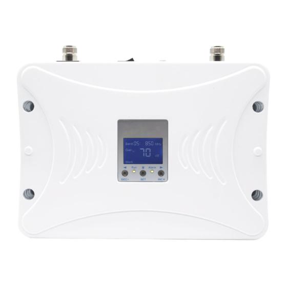
Linkage between uplink and downlink gain, keeping uplink and downlink balanced. MTBF can be up to 100,000 hours Interface Description A: N - Female Connector to outdoor antenna B: N - Female Connector to indoor antenna ... -
Page 5: Operation And Display
J : ALC alarm indicator。 K: Working status indicator Operation and display a. LCD Display After power-on and starts running, device will display frequency band on home page. It will scroll the real-time gain of UL/DL, output power of downlink, ISO and ALC alarm on the screen. - Page 6 Figure4 d. View the Gain and Gain Attenuation Setting First, select the frequency you want to set, according to precious guide of "c". Then press “SET” button to light up “Gain UL” on the screen and uplink gain will be displayed on the right side(as Figure 5).
-
Page 7: Technical Specification
Figure 9 Figure 10 f. ISO, Self-oscillation Cancellation and Auto Shut-off Device can detect the real time isolation. If isolation between outdoor and indoor antennas is insufficient, the “I.S.O” at the middle bottom of the screen will light up and ALC inside the device will work and automatically attenuate the gain to make it work normally(as Figure 11). - Page 8 Items Uplink Downlink ≥30dB Auto Level Control Range Max. input power without damage 0 dBm ≤-40 dBc Intermodulation Products ≤-36 dBm 9KHz~1GHz Spurious Emission ≤-30 dBm 1GHz~12.75GHz Manual Gain Control Range, 1dB step 0 - 31dB ≤8 dB Noise Figure ≥...
-
Page 9: Installation Guides
Items Uplink Downlink Power Consumption < 25 W RF Connector N-Female 50Ω I/O Impedance Environment Class IP40, for indoor Operating Humidity < 90% Operating Temperature -10℃ ~ +50℃ Heat Dissipation Conventional Size L206xW140xH37mm ≤ 3Kg Weight Installation Guides a. Installation Site Requirements 1) The amplifier should be installed in a place with stable and independent power supply. - Page 10 and Strength (options depends on different phone models) 2) The installation site of the indoor antenna should be in the central of the weak signal zones that you want to amplify the signal. The distance between outdoor and indoor antennas is at least 5 mts vertical or 10 mts horizontal.
-
Page 11: Antenna Connections
d. Antenna Connections Installation and connection of the antennas should follow the requirements as following: 1) Wrap the waterproof tape around the connection part of the outdoor antenna and outdoor cable, keeping it away from water oxidation and corrosion. 2) The vertical distance between the indoor and outdoor antennas should be over 5m, and the transmit direction of indoor antenna should not aim at the outdoor antenna. -
Page 12: Notices
Change the distance and ISO on the screen flashes Not enough isolation between directions of the antennas, after powered on outdoor and indoor antennas until ISO is not flashing The network of SIM card does Change SIM card or amplifier not comply with that of the amplifier Everything is okay after The indoor antenna is not...
Need help?
Do you have a question about the EP20-TB-2600 and is the answer not in the manual?
Questions and answers