Table of Contents
Advertisement
Quick Links
Advertisement
Table of Contents

Summary of Contents for Sensor LDU 68 Series
- Page 1 Ideas in Measuring .. TECHNIQUES LIMITED Load Cell Digitizing Unit Type LDU 68 Series MANUAL Firmware Version 68.181 v4.0x Website: www.sensortechniques.com e-mail: info@sensortechniques.com Tel:+44 (0)1446 771185 Fax:+44 (0)1446 771186 Page 1 LDU 68 Series Manual Issue 1h...
-
Page 2: Table Of Contents
Firmware updates for the LDU XX.X series UNIT ADAPTOR CONNECTION DETAIL UA 77.1 Unit Adaptor with built-in RS422 to RS232 converter UA73.2 Standard Unit Adaptor USB to RS422/485 CONVERTER WIRING (Multi-drop application) Page 2 LDU 68 Series Manual Issue 1h... -
Page 3: Introduction & Specifications
DAS72.1 types onto a single RS 485 bus. The LDU 68 series with its high precision 17 bit A to D converter and a mid-speed sample rate of 80 samples per second, is particularly suitable for static measurements and control. -
Page 4: Communications & Getting Started
Ideas in Measuring .. TECHNIQUES LIMITED 2 COMMUNICATIONS & GETTING STARTED 2.1 Serial Interface Communication with the LDU xx.x series is via the RS422/RS485 port. The data format is the familiar 8/N/1 structure (8 data bits, no parity, 1 stop bit). The LDU xx.x can communicate at the following baud rates: 9600, 19200, 38400, 57600, 115200 baud. -
Page 5: Setup Baud Rate / Device Address
*The DOP 4 software with graphical user interface and oscilloscope function is now available for Windows PCs. Download the latest version of the DOP 4 software from http://www.haubac.com/haubac.asp?p1=167 together with Quick Start and Users Manuals Page 5 LDU 68 Series Manual Issue 1h... -
Page 6: Hardware & Wiring
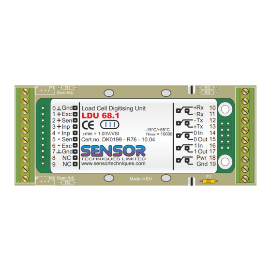
Ideas in Measuring .. TECHNIQUES LIMITED 3 HARDWARE & WIRING DIAGRAMS Standard Unit with RS422 Point to Point Connections Top view Load Cell Digitising Unit Signal gnd LDU 68.1 I I I -15°C/+55°C Dmin = 1.0mV/VSI = 10000 Cert.no. DK0199 - R76 - 10.04 +12 to 24V TECHNIQUES LIMITED www.sensortechniques.com... -
Page 7: Load Cell Connections
Where for example you are using a RS232 to RS485 converter with a supply voltage of 12 V DC, the value of R1 & R2 should be increased to 1K2 Ohms (1200 Ohms). Page 7 LDU 68 Series Manual Issue 1h... - Page 8 Ideas in Measuring .. TECHNIQUES LIMITED 3.4.3 RS485 4 Wire Multi-drop Connections Half Duplex (Recommended) Terminators - 120 Ohm Each RS485 Interface Zero Adj. Zero Adj. Load Cell Digitising Unit LDU 68.1 I I I -15°C/+55°C Dmin = 1.0mV/VSI = 10000 Cert.no.
- Page 9 Ideas in Measuring .. TECHNIQUES LIMITED This page is intentionally left blank Page 9 LDU 68 Series Manual Issue 1h...
-
Page 10: Commands Overview
Ideas in Measuring .. TECHNIQUES LIMITED COMMANDS OVERVIEW Page 10 LDU 68 Series Manual Issue 1h... - Page 11 Ideas in Measuring .. TECHNIQUES LIMITED COMMANDS OVERVIEW (Continued) Page 11 LDU 68 Series Manual Issue 1h...
-
Page 12: Commands
5.10 Setpoint Commands - Sn, Hn, An 5.11 Communication setup Commands - AD, CL, BR, DX, OP, TD 5.12 Save calibration, setup & setpoint parameters Commands - CS, WP, SS, PI, GI Page 12 LDU 68 Series Manual Issue 1h... -
Page 13: System Diagnostic Commands - Id, Iv, Is, Sr
(not used) For example the result S:067000 decodes as follows: Signal Stable (no-motion) Zero action Output 0 active Total Please note that the bits that are not used are set to zero. Page 13 LDU 68 Series Manual Issue 1h... - Page 14 This command will respond with ‘OK’ and after a maximum of 400 ms perform a complete reset of the LDU. This has the same functionality as powering off and on again (hardware reset). Page 14 LDU 68 Series Manual Issue 1h...
-
Page 15: Checkweigher Commands - Sd, Mt, Te, Tl, Tr, Ga, Sa
Ideas in Measuring .. TECHNIQUES LIMITED 5.2 Check Weigher Set up Commands SD, MT, GA, TE, TR, TL Note: All setups should be stored with the WP command before power off. SD Start Delay 0 ... 500 milliseconds Set the delay (in milliseconds) between the falling or rising edge of the trigger pulse and the start of the measurement cycle. - Page 16 Ideas in Measuring .. TECHNIQUES LIMITED TL Trigger Level (Continued) Result LDU XX.X responds Master (PC / PLC) sends Trigger Level set to 99,999 divisions T+99999 TL_1000 Trigger Level changed to 1,000 divisions See check weighing timing diagram on page 17 TR Trigger This command will start the measuring cycle immediately in the same way as the hardware trigger.
- Page 17 Ideas in Measuring .. TECHNIQUES LIMITED Timing Control Diagram Weight (g) (Trigger Edge) trigger point (Trigger Level) Time (ms) (Start Delay) (Measuring Time) Page 17 LDU68 Series Manual Issue 1h...
-
Page 18: Calibration Commands - Ce, Cm, Ds, Dp, Cz, Cg, Zt, Fd, Cs, Zi
LDU XX.X responds Master (PC / PLC) sends Display step size is set to 2 S+00002 Current TAC value is 17 E+00017 (example) CE_17 Calibration commands enabled DS_50 Display step size changed to 50 Page 18 LDU 68 Series Manual Issue 1h... - Page 19 LDU XX.X responds Zero tracking band ± 1 divisions Z+00001 Current TAC value is 17 E+00017 (example) Calibration commands enabled CE_17 ZT_2 Zero tracking band changed to ± 2 division ZT continues over ..Page 19 LDU 68 Series Manual Issue 1h...
- Page 20 LDU XX.X responds Result Master (PC / PLC) sends Initial Zero range 5 divisions R+00005 Current TAC value is 17 E+00017 (example) Calibration commands enabled CE_17 ZI_1 Initial Zero range changed to 1division Page 20 LDU 68 Series Manual Issue 1h...
-
Page 21: Motion Detection Commands - Nr, Nt
With NT = 500, the weight signal can vary no more than ± NR divisions, in the 500 ms in order to be considered stable. Factory default : NT = 1000 milliseconds. Page 21 LDU 68 Series Manual Issue 1h... -
Page 22: Filter Setting Commands - Fl, Ff, Ur
Save changes using the WP command. See table below. Result LDU XX.X responds Master (PC / PLC) sends Update Rate set to 27 measurements/sec U+00002 UR_0 Update Rate changed to 80 meas./sec. Page 22 LDU 68 Series Manual Issue 1h... -
Page 23: Set Zero/Tare And Reset Zero/Tare Commands - Sz, Rz, St, Rt
The RZ command is issued without any parameters and will return either the OK or ERR response. If the RZ command is accepted, the LDU responds with OK and the”zero action performed” bit of the device status (IS) response (see page 11) will not be active (0). Page 23 LDU 68 Series Manual Issue 1h... - Page 24 The RT command is issued without any parameters and will return either the OK or ERR response. If the RT command is accepted, the LDU will respond with OK and the “tare active” bit of the Device Status (IS) response will be set to 0 Page 24 LDU 68 Series Manual Issue 1h...
-
Page 25: Output Commands - Gg, Gn, Gt, Gs, Gf, Gw, Ga
The last two hexadecimal characters represent the checksum, which is the inverse of the sum of all the ASCII values of the string plus 1, not including the checksum characters. Page 25 LDU 68 Series Manual Issue 1h... - Page 26 Please note that during the period after the measuring cycle has been triggered but before the value of GA has been updated, the GA command will return a value 99999. See Checkweigher commands section 5.2 Page 26 LDU 68 Series Manual Issue 1h...
-
Page 27: Auto-Transmit Commands - Sg, Sn, Sf, Sw, Sa
Please note that during the period after the measuring cycle has been triggered but before the value of SA has been updated, the SA command will return a value 99999. See the check weighing timing diagram on page 17. Page 27 LDU 68 Series Manual Issue 1h... -
Page 28: Commands For External I/O Control - In, Io, Im
LDU, the output 0 will be activated (FET conducting). Setting Master ( PC / PLC ) sends LDU XX.X responds Result Output 0 active IO_0001 IO_0010 Output 1 active IO_0011 Output 0+1 active Page 28 LDU 68 Series Manual Issue 1h... - Page 29 Note: When reading the status of the logic outputs using the IO command, the setpoint status will be returned regardless of the IM setting. Sending IM 0000 disables the external logic output control. Factory default:- IM= 0000 Page 29 LDU 68 Series Manual Issue 1h...
-
Page 30: Setpoint Commands - Sn, Hn, An
When the weight is increasing between 0 kg and 1999 kg the logic output is “OFF”. Once the weight increases above 1999 kg, the logic output is “ON”. The logic output will switch “OFF” again when the weight value drops below 1900 kg. Page 30 LDU 68 Series Manual Issue 1h... - Page 31 Similarly, to read or change the base for the setpoint of logic 1, issue the commands as above but substitute A1 instead of A0. NOTE: All changes to the setpoint settings have to be stored in EEPROM using the SS command. See section 5.11 Page 31 LDU 68 Series Manual Issue 1e...
-
Page 32: Communication Setup Commands - Ad, Cl, Br, Dx, Op, Td
Communication changed to full duplex Half duplex communication can be used for 2 wire RS485 communication. The auto transmit commands SG and SF will only work if full duplex (DX=1) is selected. Factory default DX=0 Page 32 LDU 68 Series Manual Issue 1h... - Page 33 This command is particularly useful when LDUs are used on a 2 wire RS485 bus where the host PLC is unable to ‘turn around’ the transmit and receive lines quick enough to prevent missing part or all of the answer. Page 33 LDU 68 Series Manual Issue 1h...
-
Page 34: Save Calibration, Setup & Setpoint Parameters Commands - Cs, Wp, Ss, Gi, Pi
LDU and write it to a number of other LDUs for “cloning”. These commands are useful if you want to set up a large number of LDUs in the same way e.g. in some kind of production. Page 34 LDU 68 Series Manual Issue 1h... -
Page 35: Calibration Procedure
Setting: decimal point 0000.0 CE_17 Calibration sequence active Save calibration data in EEPROM Zero point, gain and decimal point position were saved in the EEPROM; the calibration counter (TAC) is increased automatically by 1. Issue 1h Page 35 LDU 68 Series Manual... -
Page 36: Use In "Approved" Applications (Ldu 68.1 Only)
Trading Standards Office, will result in legal prosecution of the user. The user software is required as a condition of approval, to make the TAC available to the weight display indicator or console, on demand. Page 36 LDU 68 Series Manual Issue 1h... -
Page 37: Software (Firmware) Downloads
(FD) Please note that the FD command is TAC protected. You must issue the CE command with the relevant TAC code prior to the FD command otherwise the FD command will fail. Page 37 LDU 68 Series Manual Issue 1h... -
Page 38: Unit Adaptor Connection Detail
Dmin = 1.0mV/VSI = 10000 Cert.no. DK0199 - R76 - 10.04 LOGIC I/O TECHNIQUES LIMITED www.sensortechniques.com +12 - 24V P2 Span Adj. Span Adj. Made in EU Made in EU Buss 400mA Page 38 LDU 68 Series Manual Issue 1h... -
Page 39: Ua73.2 Standard Unit Adaptor
Dmin = 1.0mV/VSI = 10000 Cert.no. DK0199 - R76 - 10.04 LOGIC I/O TECHNIQUES LIMITED www.sensortechniques.com +12 - 24V P2 Span Adj. Span Adj. Made in EU Made in EU Buss 400mA Page 39 LDU 68 Series Manual Issue 1h... -
Page 40: Usb To Rs422/485 Converter Wiring (Multi-Drop Application)
The following example shows how to wire up 2 or more LDU 68.xs in a multi-drop application to an USB port of a PC using a USB to RS422/485 converter. This circuit has been tested and is known to work correctly. The USB to RS422/485 converters can be purchased from Sensor Techniques Limited...
Need help?
Do you have a question about the LDU 68 Series and is the answer not in the manual?
Questions and answers