Table of Contents
Advertisement
Quick Links
Advertisement
Table of Contents

Related Manuals for Eico 753

Summary of Contents for Eico 753
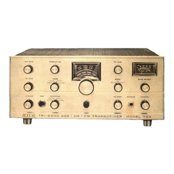
- Page 1 753/Tri-Band SSB/AM/CW Transceiver Rev.I...
-
Page 2: General Description
In fixed station use, the Model 751 AC Supply/Speaker Console (117 VAC, 60 cps) is required for its operation. In mobile use, the Model 752 DC Supply (12 VDC , positive or negative ground) is required. Both supplies have been designed integrally with the 753 and provide the requisite filtering and regulation. - Page 3 This facilitates servicing, or , if desired, double use of the Model 753 as both a mobile and f ixed station. Fig. 2 provides all the requir ed infor mation for installing the mounting bracket and for attaching the trans- ceiver to the bracket.
- Page 4 HIGH POWER LINEAR COIL -- - - - - - - - - - VOLTAGE ANTENNA EXTERNAL FIGURE 1 JACK RELAY {MODEL 753) {MODEL 753) FIGURE 2 WARNING AVOID PLACING THE TRANSCEIVER IN OR NEAR HOT AIR STREAM. TO REAR...
-
Page 5: Operation
MICROPHONE CONNECTIONS An Amphenol Type MC2M plug, or the equivalent, must be used for connecting the microphone the panel MIC receptacle. The microphone may be either a high impedance dynamic (preferred) or a ceramic type. Since all necessary audio bandwidth restriction is incorporated in the transceiver circuitry, a wide-range, high quality dynamic mike may be used and is most desirable. - Page 6 CARRIE R BALANCE control as described in step 3a (and the rear apron BIAS adjust, as given in the NOTE following 3a, if this is the first time the 753 is placed in operation). 4. Reset the MODE switch at TUNE and adjust EXCITE R tune and PA TUNE as described in steps 1 and 2.
- Page 7 Set the rear apron VOX controls as follows: VOX-SE NSITIVITY ....fully cw (max. sensitivity) VOX- THRESHOLD ..• ..fully cw (guaranteed to return to receive) VOX-DE LAY.
- Page 8 CW station. AM OPERATION The following procedure is based on the assumption that the 753 has been set up for SSB opera- tion, and that it is now intended to operate AM. Set the FUNCTION switch at either VOX or PTT, depending on the desired type of operation.
-
Page 9: Mode Switch
This will require a lower setting of the MIC GAIN control than is used in SSB opera- tion. 8. The 753 is now properly set up for AM operation. Least distortion on AM reception will usually be obtained when tuned slightly to one side of "peak". -
Page 10: Circuit Description
CALIBRATION AC TIVATION The 753 provides power and input connections for a lOOkc crystal oscillator employing a tube with a 12. volt heater. A 4-pin plug (EBY 11'9721-71) must be wired to the calibrator connection cable as follows: pin 1: 12. - Page 11 dynamically grounded plate is adjusted with R20 to control the balance of the modulator. This balance is automatically upset in the AM mode by connection of R42 from one deflection plate to ground. Out- put is taken across the two anodes of the 7360, and coupled to the four pole crystal f ilter by means of T l.
-
Page 12: Maintenance
the bias on CR6 is taken from a fixed center-tap on R48, so that the frequency is independent of the setting of the RECEIVER OFFSE T tuning control. The r eceiver and transmitter will operate on the same frequency when the control is set at mid-rotation (center line on panel). VOX CIRC UIT A six pole relay controls the voltage and biases to the various stages of the transceiver , and deter mines whether the unit is in the receive or transmit condition. -
Page 13: Alignment Procedure
RECEIVE R ALIGNMENT a) IF Strip The transceiver should be connected to the EICO 751 (or 752) power supply. There should be no microphone connected to the unit at this time. Before turning the unit on, set the controls as follows: MIC GAIN . - Page 14 3. Apply an unmodulated 7. OOMc signal to the ANTE NNA connector on the rear apron. This signal should be quite weak (approximately lOOuV), which may require very loose coupling between the signal generator or oscillator to the transceiver. 4. Set the FUNCTION switch at STANDBY, and af ter one or two minutes of warmup, turn it to PTT.
- Page 15 CI07 6A05 6 BE6 7199 60 0 68 §60· ,· " " ../ '#- 60068 • • 6BA6 12AX7 .i:.. 12BY7A -· -· · · · • 12AZ7A 12AX7 6BA6 6BA6...
- Page 16 FIGURE 5...
-
Page 17: Crystal Filter
Set the FUNC TION switch at STANDBY, and, af ter one or two minutes of war m-up, reset the FUNC TION switch at PTT. Depress the microphone PTT button, and adjust the rear apron BIAS control for a meter reading of 50mA. Release the mic rophone PTT button. - Page 18 DC voltages, Columns B and C , only the power supply is connected to the unit. The readings given are those to be expected when using the EICO Model 751 AC power supply under normal ( 1l7V) line voltage conditions.
- Page 19 VOLTAGE AND RESISTANCE CHART DC VOLTAGE RESISTANCE DC VOLTAGE WITH RESPEC T WITH RESPECT CHASSIS TO CHASSIS TO CHASSIS TUBE 475K lOOK 2. 2K 12. 6 AC 12. 6 AC 12. 6 AC 12. 6 AC lOOK -42V -100 6. 3 AC 6.
- Page 20 TUBE 620K 12. 6 AC 12. 6 AC 6. 3 AC 6. 3 AC 1 Meg* V l2 5600 -50 V 5600 6. 3 AC 6. 3 AC 130K 12. 6 AC 12. 6 AC 6. 3 AC 6. 3 AC 2.
- Page 21 XMTR ..MIC AMPL BAL MOD XTAL COMMON ..I FROM MIC AMPL MIXER FILTER MIC --, V IA V IB ..,.._ ..- _ R _, V l2 • V l3 SPKR 1""11111""" • A LC ..XTAL OSC AF POWER POWER RELAY AMPL...
- Page 22 PRICE PRICE EACH SYM. # STOCK# DESCRIPTION EACH SYM. # STOCK# DESCRIPTION 21254 molded s. m. , 300pf , CAPACITORS 300V, 5% (In UF, unless otherwise specified) 21256 . 23 C76, 90, molded s. m. , 62pf , 300V, 5% .
-
Page 23: Parts List
PARTS LIST PRICE PRICE STOCK# SYM.# EACH DESCRIPTION STOCK# DESCRIPTION EACH SYM.# ME TER 11540 . 14 R37, 116 12. 50 10601 33Kn, 2W, 5% 75006 meter, lma (includes 18156 2 pot board 3. 61 R39, 108 lamp PL 2) 10455 l. - Page 24 PRICE PRICE EACH SYM. # STOCK# DESCRIPTION EACH SYM. # STOCK# DESCRIPTION . 20 XV5, 6, 7 97055 TRANSFORME RS 7 pin socket (printed circuit) 2. 82 34649 interstage 97056 9 pin socket (printed 2.58 34650 filter coil (output) circuit) .
- Page 25 PRICE PRICE STK. # DESCRIPTION EACH EA CH SYM.# STOCK# DESCRIPTION 58448 RG174/U, red .06/f t. . 20 XV5, 6, 7 97055 7 pin socket (printed 58450 . 06/f t. RG174/U, yellow circuit) 58451 RG174/U, blue .06/f t. . 25 97056 9 pin socket (printed .
- Page 26 It is not known whether the penciled-in mark-ups on the schematic and parts list are accurate for all versions of the Eico 753 or only certain serial numbers. They were on the manual when I received it.
- Page 27 ---' · " 2 w-+-+-.!..-- : .c;;; :': :===============l PHONES Rl07 .QQ5 52 MODE RI03 2.21.4 6A05 = JACK 470K L_ _ 220K · RELAY SI FUNCTION $4 ON R5 6BE6 47fi ,--c:c-!W'-.; - + __. 47fi EICO 7 5 3 SCHEMATIC DIAGRAM...
- Page 28 ,- - - - - -- · nt- p IOOK 4.7K r _ _ Ti_ _ , 470K :R K . 0 015 ...-Ut- · - i t--. .- - - - ... l/2 12AX7 . 0 01 7360 6 - 7 e--<=- - - - - - - - - - - - - - 1/2 12AX- 47 K...
- Page 29 2.2 K lcs9 II:" §f F. STRIP .1 : : '.J.005 I -- -- 1 2.2K < PC SOARD -,!,-C54 < " I 11 1 J_c120 ..._. I.05 ' ? J 1""""1--1 ) "' . : h H1-1 LT3 _J :"rf:t- 15:0 L' - ---J...
- Page 30 t----= li1 - ;:;f:C S _ 4 -3 _ 3 2 .-- - - - r 26 I R O F O C µh 22 K Rl29 ; j c 42 _l_c39 '"'· ·I · 1 2·141 PO 1 %2 750 Vl5 tlo 4a 'ls C 45 METER...
- Page 31 === LIO RIOI Rl05 >05 IOOK CIOI RI04 Riii 2.2K 470fi RI02 IK,2W RI09 +250V 170MA -IOOV S4 ON R5 6BE6 47fi 1oon 6BA6 RF GAIN 47!1 12.sv 4 AMPS 115V AC 12V DC EICO 7 5 3 SCHEMATIC DIAGRAM...
- Page 32 ENJOY YOUR BOOKS PLEASE VISIT OUR STORE FOR EVEN MORE GREAT STUFF! WWW.EVERYTHING4LESSSTORE.COM COPYRIGHT NOTICE ALL MATERIALS INCLUDING CD/DVD AND PDF FILES ARE COPYRIGHTED WWW.EVERYTHING4LESSSTORE.COM VON WALTHOUR PRODUCTIONS AND MAY NOT BE REPRODUCED, COPIED OR RESOLD UNDER ANY CIRCUMSTANCES. YOU MAY HOWEVER MAKE A COPY FOR YOUR OWN PERSONAL BACKUP.
- Page 33 Since 1945, EICO been recognized as a leader the design and manufacture of electronic products in ki t form.The wide range of equipment that EICO has made available covers nearly every phase of electronics-High Fidelity (Receivers, Amplifiers, Tuners and Speakers) tape recorders;...
Need help?
Do you have a question about the 753 and is the answer not in the manual?
Questions and answers
Incorrect part designator. on pg.12 line 2.- connect cap 20/50Pf from pin 3 of V4 to pin 7of v17.. V17 does not exist check schematics. Eico 573.
The context does not provide specific information about an Eico 573. However, for the Eico 753, if V17 does not exist, the connection involving pin 3 of V4 to pin 7 of V17 cannot be made as described. In that case, the temporary capacitor connection step should be skipped or adjusted based on the actual circuit configuration.
This answer is automatically generated