Advertisement
Quick Links
NATIONAL AIR
BH Vibrator Operation, Maintenance, and Troubleshooting
Air Control Connection:
1.
Install air control package (Figure 1).
2.
Blow out air line to flush contaminants before
connecting the vibrator.
3.
Fill the lubricator with recommended lubricant or oil
(see Lubrication Recommendation Bulletin 4000.503).
4.
Open valve.
5.
Set the pressure regulator to 50 PSI (see FRL
instructions).
6.
Adjust the lubricator to recommended setting (see
Lubrication Recommendation Bulletin 4000.503).
7.
Adjust air regulator to the lowest pressure that will
give the desired material flow performance, NOT to
exceed 60 PSI.
Installation Note: All vibrators must be installed with a filter,
regulator, and lubricator (FRL).
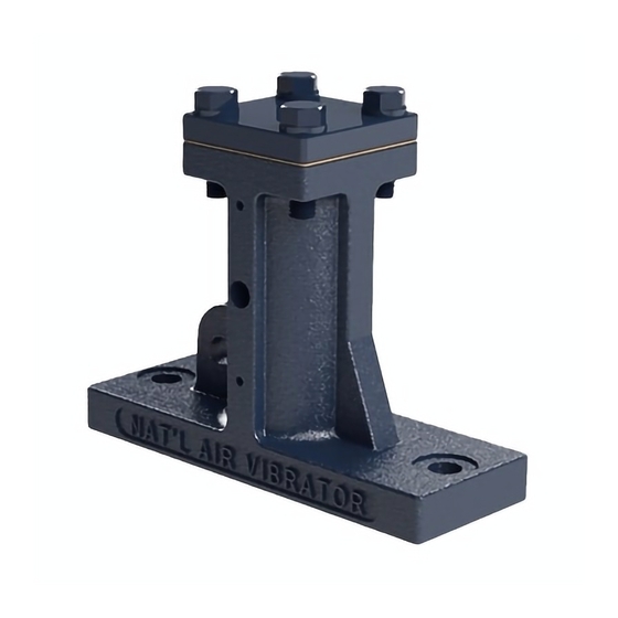
Figure 1 (Air inlet located on top headplate for single impact
BH models)
Maintenance:
1.
Check lubricator and fill with recommended oil type if
level is low (see Lubrication Recommendation Bulletin
4000.503).
2.
Check that air pressure is correctly set for
most efficient operation. Drain filter to remove
contaminants (water, scale, etc).
3.
Check all air connections and tighten if necessary.
4.
Torque all bolts that may have been loosened over a
period of time (maintenance/plant-shutdown).
5.
Be certain vibrator is well lubricated at all times. One
way to check this is to place hand over exhaust while
running. A fine film of oil on the palm of the hand will
confirm that the vibrator is being lubricated properly.
®
V I B R ATO R C O.
Vibration Technology for Processing Bulk Materials
Mounting With Channel Mounting:
Note: Use channel mounting plate (See Figure 2). Safety cable
recommended.
1.
Determine proper mounting location. Assure a
mounting angle greater than 20° unless an internal
spring is installed.
2.
Skip-weld reinforcing bars to hopper. Do not weld
corners.
3.
Skip-weld both channel legs to reinforcing bars. Do not
weld corners.
4.
Install vibrator and mounting bolts.
5.
Install lock washer (if included) and nut. Torque
mounting hardware to recommended specification.
(See Bin Hopper (BH) Vibrator Operation Manual)
6.
Re-torque mounting hardware after 24 hours of
equipment operation.
Figure 2
Mounting With T-Slot Mounting Plate:
Note: Use T-slotted mounting plate (See Figure 3). Safety
cable recommended.
1.
Determine proper mounting location. Assure a
mounting angle greater than 20°, unless internal
spring is installed.
2.
Skip-weld reinforcing plate to hopper. Do not weld
corners.
3.
Skip weld t-slot to reinforcing plate. Do not weld
corners.
4.
Insert bolts in slots and position vibrator onto t-slot.
5.
Install lock washer and nut. Torque mounting
hardware to recommended specification. (See Bin
Hopper (BH) Vibrator Operation Manual)
6.
Re-torque mounting hardware after 24 hours of
equipment operation.
Bulletin: 4000.501
Figure 3
Advertisement

Related Manuals for NAVCO BH Vibrator

Summary of Contents for NAVCO BH Vibrator
- Page 1 Vibration Technology for Processing Bulk Materials Bulletin: 4000.501 NATIONAL AIR V I B R ATO R C O. BH Vibrator Operation, Maintenance, and Troubleshooting Mounting With Channel Mounting: Air Control Connection: Install air control package (Figure 1). Note: Use channel mounting plate (See Figure 2). Safety cable recommended.
- Page 2 For additional information consult the Bin Hopper (BH) Vibrator Operation Manual, available at our website, or contact NAVCO directly. Limited Warranty Seller warrants that the product purchased will be of the kind and quality described in the order or contract and will be free of defects in workmanship or material.
Need help?
Do you have a question about the BH Vibrator and is the answer not in the manual?
Questions and answers