
Summary of Contents for Hiniker DB-7929-1
- Page 1 HINIKER SNOW PLOW HYDRAULIC UNIT POWER UNITS DB-7929-1, DB-7929-2 & DB-7929-3 SERVICE MANUAL DO NOT USE OR OPERATE THIS EQUIPMENT UNTIL THIS MANUAL HAS BEEN READ AND THOROUGHLY UNDERSTOOD PART NUMBER 25012811...
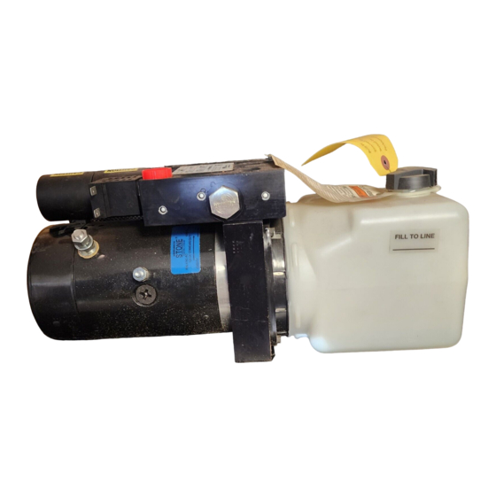
- Page 3 Releasing the Raise switch de-energizes the 12 VDC motor. The raise circuit is protected by a The hydraulic power unit DB-7929-1 consists of pressure relief valve set to relieve system pres- a 12 VDC motor, a hydraulic pump rated at 1.3...
- Page 4 Power Unit - Hydraulic POWER UNIT - STRAIGHT AND SCOOP PLOW DWG. NO. 6586...
- Page 5 Power Unit - Hydraulic Circuit Diagram POWER UNIT - HYDRAULIC CIRCUIT DIAGRAM DWG. NO. 4180A...
- Page 6 Power Unit - Component Location POWER UNIT - COMPONENT LOCATION DWG. NO. 6528 REF. PART REF. PART DESCRIPTION QTY. DESCRIPTION QTY. NUMBER NUMBER 25010734 Pump Assembly DB7929-3 25012673 Ground Stud 25011706 Pump Assembly DB7929-2 952-001-001 Lock Washer 1/4 Inch 25010239 Pump Assembly DB7929-1 951-001-003 Hex Nut 1/4-20...
-
Page 7: Table Of Contents
Table of Contents 1 TABLE OF CONTENTS 2502811 6/10 Manual/25012811 Troubleshooting Procedures ....................2 Plow Will Not Raise ......................3 Plow Will Not Angle Or Angles In One Direction Only ............4 No Plow Functions Except Down ..................5 Plow Angles Slowly ......................6 Plow Lifts Slowly ......................... -
Page 8: Troubleshooting Procedures
Make sure battery is charged and charging system is in good condition. This section is designed to help you troubleshoot the hydraulic system on the Hiniker Snow Plow. Check 10 AMP fuse in relay/junction box Each procedure consists of a detailed problem located on the Underhood Wiring Harness. -
Page 9: Plow Will Not Raise
NC Release Valve Coil. Does pump motor run? Is screwdriver attracted to nut end of coil? Refer to electrical troubleshooting. Call Hiniker Service Does Plow Raise? Remove, inspect and clean Adjustable Re- lief Valve. Repair or replace as necessary. See page 14. -
Page 10: Plow Will Not Angle Or Angles In One Direction Only
Does pump motor run? Does plow angle both ways? Does plow angle both ways? Call Hiniker Service Remove, clean and inspect RV1 & RV2 Re- lief Valves. See page 19. Repair or replace as necessary. Reinstall. Adjust pressure. See page 29-30. -
Page 11: No Plow Functions Except Down
No Plow Functions Except Down 5 NO PLOW FUNCTIONS EXCEPT DOWN Perform all initial inspections and checks listed on page 2 before beginning test procedure. Note: When performing the following test procedures, make sure that you test to the vehicle battery terminals, not to the vehicle ground or DC motor ground. -
Page 12: Plow Angles Slowly
Check for a binding cylinder by manually compressing and extending cyl- inders by hand. Repair or replace as nec- essary. Does plow angle fully left and right from center in approximately 2 seconds? DWG NO. 3066 Call Hiniker Service... -
Page 13: Plow Lifts Slowly
Remove lift cylinder and drain oil. Check for a binding cylinder by manu- ally compressing and extending the cylinder. Repair or replace as necessary. Does plow lift fully up in approximately 2 seconds? DWG NO. 3066 Call Hiniker Service... -
Page 14: Plow Will Not Hold Angle
PLOW WILL NOT HOLD ANGLE. ALL OTHER FUNCTIONS ARE NORMAL. REMOVE, INSPECT AND CLEAN RELIEF VALVES. SEE PAGE 19. ADJUST PRESSURE. SEE PAGE 29-30. DOES PLOW HOLD ANGLE? Remove, inspect and clean Directional Valve. See page 17-18. Does plow hold angle? Call Hiniker Service... -
Page 15: Plow Will Not Stay Up
Off. Verify that there is no voltage at the NC Re- lease Valve, using a voltmeter or test light. Is voltage present? Refer to electrical troubleshooting. Does Plow Stay Up? Call Hiniker Service Call Hiniker Service... -
Page 16: Plow Will Not Lower
Check for plugged fittings, hydraulic hose and external flow control valve. Remove and drain oil from lift cylinder. Check for frozen/binding cylinder by manually com- pressing and extending the cylinders. Repair or replace as necessary. Does plow lower? Call Hiniker Service... -
Page 17: Dc Motor Removal And Replacement
DC Motor Removal and Replacement 11 DC MOTOR REMOVAL AND REPLACEMENT WARNING: Disconnect Vehicle Battery Hold motor together while removing it from the prior to performing this procedure to end head. avoid electrical shock or burns. NOTE: If oil is found in the cavity of the valve passage where the coupling is located, replace- ment of the oil pump shaft seal is necessary be- fore the unit can be put back into service. -
Page 18: Dc Motor Brush Removal And Replacement
12 DC Motor Brush Removal and Replacement DC MOTOR BRUSH REMOVAL AND REPLACEMENT WARNING: Disconnect Vehicle Battery NOTE: If your motor is equipped with two (2) prior to performing this procedure to brushes with bare wires (Ground brushes) and avoid electrical shock or burns. two (2) brushes with insulated wires (POS brush- es), make sure that you note location of the two types and replace them with like type brushes. -
Page 19: Check Valve Removal, Cleaning And Replacement 13
Check Valve Removal, Cleaning and Replacement 13 CHECK VALVE REMOVAL, CLEANING & REPLACEMENT WARNING: Never disconnect any hy- Inspect the ball and ball seat for wear, gouges draulic line or fitting with the unit in or pitting. Replace the assembly as necessary. the raised position. -
Page 20: Adjustable Relief Valve Removal, Cleaning And Replacement
14 Relief Valve Removal, Cleaning & Replacement RELIEF VALVE REMOVAL, CLEANING AND REPLACEMENT WARNING: Never disconnect any hy- draulic line or fitting with the unit in the raised position. Always lower the unit and relieve pressure before removing BALL ADJ. SCREW VALVE CAP any lines or caps. -
Page 21: Normally Closed (Nc) Release Valve Removal, Cleaning And Replacement
Normally Closed (NC) Release Valve Replacement 15 NORMALLY CLOSED (NC) RELEASE VALVE REMOVAL, CLEANING AND REPLACEMENT WARNING: Disconnect Vehicle Bat- Remove the release valve solenoid nut with a tery prior to performing this procedure 3/4” wrench. Remove coil from cartridge. Re- to avoid electrical shock or burns. -
Page 22: Valve Removal And Replacement
16 U- Valve Removal and Replacement VALVE REMOVAL AND REPLACEMENT WARNING: Never disconnect any hy- draulic line or fitting with the unit in the raised position. Always lower the unit and relieve pressure before removing any lines or caps. Allow the system to cool down before draining oil or handling system components. -
Page 23: Directional Solenoid Valve Removal, Cleaning And Replacement
Directional Solenoid Valve Replacement 17 DIRECTIONAL SOLENOID VALVE REMOVAL, CLEANING AND REPLACEMENT WARNING: Disconnect Vehicle Battery Remove coil nut with 3/4” wrench. prior to performing this procedure to avoid electrical shock or burns. Mark or make note of the solenoid coil posi- tion for reinstallation. - Page 24 18 Directional Solenoid Valve Replacement Re-install cartridge valve. Torque cartridge valve to 10-15 ft. lbs. PHOTO NO. 1000296 Install coils, spacer and nut. Torque nut to 5-15 In. Lbs. CAUTION: DO NOT overtighten the coil nut. The coil shaft can be easily damaged requiring replacement.
-
Page 25: Directional Relief Valve Removal, Cleaning And Replacement
Crossover Relief Valve Replacement 19 DIRECTIONAL RELIEF VALVE REMOVAL, CLEANING AND REPLACEMENT WARNING: Never disconnect any hy- draulic line or fitting with the unit in the raised position. Always lower the unit and relieve pressure before removing any lines or caps. Allow the system to cool down before draining oil or handling system components. -
Page 26: Hydraulic Pump Removal, Cleaning And Replacement
20 Hydraulic Pump Replacement HYDRAULIC PUMP REMOVAL, CLEANING AND REPLACEMENT Remove the inlet filter by pulling it straight off WARNING: Never disconnect any hy- the barbed end of the plumbing elbow. The fil- draulic line or fitting with the unit in the raised position. - Page 27 Hydraulic Pump Replacement 21 Remove the coupling attached to the motor by pulling out with a pencil magnet. MOUNTING BOLT Clean and inspect all machined surfaces for contamination, distortion, and wear. Inspect the inlet suction cover and look for cracks and con- tamination.
- Page 28 22 Hydraulic Pump Replacement PHOTO NO. 1000338 Carefully re-install the new filter onto the suction tube. Visually check that the inlet pick up tube and suction screen face down towards the bot- tom of the reservoir. Clean the inside of the reservoir with a suitable solvent.
-
Page 29: Electrical/Hydraulic Troubleshooting
Electrical/Hydraulic Trouble Shooting 23 ELECTRICAL/HYDRAULIC TROUBLE SHOOTING WARNING: Stand clear of the moldboard If voltage is present between points 2 & 3 and other moving parts while perform- when DOWN is activated, but the moldboard ing these tests. does not drop, the problem is with the hydrau- lic unit. -
Page 30: Hydraulic Pump Test
24 Hydraulic Pump Test HYDRAULIC PUMP TEST WARNING: Never disconnect any hy- Turn ignition switch On and hold the joystick in draulic line or fitting with the unit in the Up position. The gauge should be indicat- the raised position. Always lower the ing 2000 PSI + / - 100 PSI, Home Owner and unit and relieve pressure before removing Steel Straight Plows. -
Page 31: Dc Motor Current Draw (Full Load)
DC Motor Current Draw (Full Load) 25 DC MOTOR CURRENT DRAW (FULL LOAD) Equipment: Inductive Pickup Amp Meter Park vehicle in an area with adequate ventilation and with enough room to safely, raise the plow. WARNING: This test is extremely dan- gerous and should not be attempted by anyone that is not familiar with testing electrical components capable of... -
Page 32: Dc Motor Current Draw (No Load)
26 DC Motor Current Draw (No Load) DC MOTOR CURRENT DRAW (NO LOAD) Equipment: Inductive Pickup Amp Meter This test is extremely dangerous and MOTOR AMP METER POWER should not be attempted by anyone BATTERY that is not familiar with testing electri- POSITIVE TERMINAL cal components capable of High Amp Draw! -
Page 33: Normally Closed (Nc) Release Valve Test
Normally Closed (NC) Release Valve Test 27 NORMALLY CLOSED (NC) RELEASE VALVE TEST WARNING: This procedure requires If battery voltage if present, replace the coil. that the plow be raised and/or low- See page 15. ered. Stand clear of plow when it is raised and/or lowered. -
Page 34: Directional Solenoid Valve Test
28 Directional Solenoid Valve Test DIRECTIONAL SOLENOID VALVE TEST WARNING: Never disconnect any hy- If battery voltage is present, replace the coil. draulic line or fitting with the unit in the raised position. Always lower the If no voltage is indicated, check wiring, joystick unit and relieve pressure before removing and grounds, repair or replace as necessary. -
Page 35: Directional Relief Valve Testing And Adjustment
Crossover Relief Valve Testing and Adjustment 29 DIRECTIONAL RELIEF VALVE TESTING AND ADJUSTMENT WARNING: Never disconnect any hy- draulic line or fitting with the unit in the raised position. Always lower the unit and relieve pressure before removing any lines or caps. Allow the system to cool down before draining oil or handling system components. - Page 36 30 Crossover Relief Valve Testing & Adjustment Adjustment: PHOTO NO. 1000296C NOTE: Adjustments should be made in 1/2 turn increments. Remove the Allen cap. To adjust port “A” turn Allen screw or RV2. To adjust Port “B” turn Allen screw on RV1. The Allen screw underneath the cap is for adjusting the relief valve pressure set- ting.
-
Page 37: Adjustable Relief Valve Testing And Adjustment
Adjustable Relief Valve Testing and Adjustment 31 ADJUSTABLE RELIEF VALVE TESTING AND ADJUSTMENT Carefully disconnect the hydraulic fitting from WARNING: Never disconnect any hy- draulic line or fitting with the unit in the valve assembly. the raised position. Always lower the Using the proper fittings, install a 0-3000 PSI unit and relieve pressure before removing any lines or caps. - Page 38 32 Adjustable Relief Valve Testing & Adjustment WARNING: Always lower the plow and relieve pressure before removing any lines or caps. Remove the hex cap located on the rear of the valve assembly. The slotted screw underneath the cap is for ad- justing the relief valve pressure setting.
- Page 39 Notes 33 NOTES:...
Need help?
Do you have a question about the DB-7929-1 and is the answer not in the manual?
Questions and answers