Table of Contents
Advertisement
Quick Links
Thundercomm
Thundercomm TurboX
A high performance embedded platform based on Qualcomm® Snapdragon ™ 845
processor
Description
Thundercomm TurboX
TM
Android or Linux system, based on Qualcomm SDA845 processor. It integrates the advanced 10 nm Fin FET
process, a customized 64-bit ARM v8-compliant Octacore Qualcomm Kryo 385 applications processor.
TurboX D845 SOM supports short-range wireless communication through Wi-Fi 802.11 a/b/g/n/ac and BT5.0.
This SOM supports 3840*2400@60fps display, it can connect 4 x camera modules, and integrating multiple
audio and video input/output interfaces.
interfaces. In addition, it supports two MIPI-DSI, four MIPI-CSI and SOM common standard protocol
interfaces such as USB3.1, PCIE2.1/3.0, I2S and SLIMBUS.
TurboX D845 SOM provides convenient and stable system solution for IOT field, it can be embedded into the
device on VR/AR, Drone, Robot, Smart Camera, AI devices, and any other connecting fields. The size of
module is 37mm x 60mm x 7.1mm, weight 10.3g, with 336PINs.
Features
The following table shows the detailed features and performance on TurboX D845 SOM.
Processors
Applications
Processor
Digital signal
processing
Copyright © 2018 All Rights Reserved , Thundercomm Technology Co., Ltd.
D845 System on Module(SOM) is a high performance intelligent module, integrating
This SOM provides a variety of GPIO, I2C, UART and SPI standard
64-bit applications processor (Kryo 385) with 2 MB L3 cache
Quad high-performance Kryo cores at 2.649 GHz - Kryo Gold cluster with 256 kB L2
cache per core
Quad low-power Kryo cores at 1.766 GHz - Kyro Silver cluster with 128 kB L2 cache
per core
Compute DSP with Qualcomm Hexagon Vector Extensions (dual-HVX512) processor
TurboX D845 System on Module
D845 System on Module
TM
1
Advertisement
Table of Contents

Subscribe to Our Youtube Channel
Summary of Contents for Thundercomm TurboX D845
- Page 1 USB3.1, PCIE2.1/3.0, I2S and SLIMBUS. TurboX D845 SOM provides convenient and stable system solution for IOT field, it can be embedded into the device on VR/AR, Drone, Robot, Smart Camera, AI devices, and any other connecting fields. The size of module is 37mm x 60mm x 7.1mm, weight 10.3g, with 336PINs.
- Page 2 4K60 decode for H.264 High Profile, H265 Main 10 Profile and VP9 Profile 2 Graphics Adreno 630 - 4K 60 fps UI or 2x 2k x 2k 90 fps UI Copyright © 2018 All Rights Reserved , Thundercomm Technology Co., Ltd.
- Page 3 Qualcomm enhance 3D audio solution, Qualcomm stereo audio expansion feature, and Qualcomm intelligent mixing algorithm Wireless connectivity 2.4G/5G, support 802.11 a/b/g/n/ac, 2 X 2 MIMO WLAN Support Bluetooth 5.0 + HS Bluetooth Connectivity Copyright © 2018 All Rights Reserved , Thundercomm Technology Co., Ltd.
- Page 4 Capacitive panels via ext IC (I2C, and interrupts) support Size: 37mm x 60mm x7.1mm Physical size Weight: approx. 10.3g Interface: Connector Operating -20~50℃ temperature RoHS All hardware components are fully compliant with EU RoHS directive Copyright © 2018 All Rights Reserved , Thundercomm Technology Co., Ltd.
- Page 5 Thundercomm TurboX D845 System on Module Applications TurboX D845 SOM is ideal for many applications including (but not limited to): AI, Robotics, Virtual Reality (VR), Augmented Reality (AR),Drones and Medical Devices. Revision History: Version Date Description V1.0 July 31, 2018 Revised Release V1.1...
-
Page 6: Table Of Contents
Audio Interface..........................20 3.2.6 USB & DisplayPort Interface.......................21 3.2.7 PCIe Interface..........................22 3.2.8 SSC Interface..........................23 3.2.9 SDIO Interface..........................24 3.2.10 QUP Interface..........................24 3.2.11 Power on Interface........................25 3.2.12 Reset Interface..........................26 Copyright © 2018 All Rights Reserved , Thundercomm Technology Co., Ltd. - Page 7 Digital GPIO characteristics..................... 38 5.3.2 SD card digital I/O characteristics....................39 MIPI..............................40 USB...............................40 PCIe..............................40 DisplayPort............................41 SLIMbus............................... 41 SDIO..............................41 5.10 I2S.................................41 5.11 I2C................................ 43 5.12 SPI.................................43 5.13 Fuel gauge.............................44 Copyright © 2018 All Rights Reserved , Thundercomm Technology Co., Ltd.
- Page 8 Thundercomm TurboX D845 System on Module 5.14 LED Current Driver..........................44 5.15 ADC..............................45 5.16 Power Consumption..........................46 5.17 Thermal..............................46 Copyright © 2018 All Rights Reserved , Thundercomm Technology Co., Ltd.
-
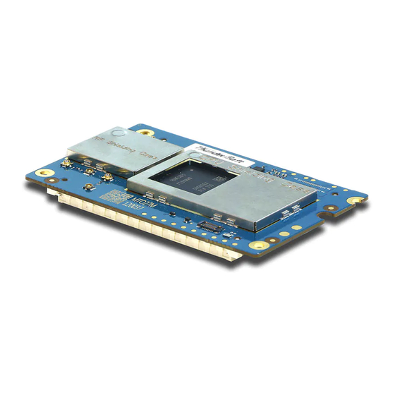
Page 9: Physical Description
TurboX D845 System on Module 1 Physical Description 1.1 Major Components Location TurboX D845 SOM’s major components as below map. Figure 1.1- 1 TurboX D845 SOM Key component Location Copyright © 2018 All Rights Reserved , Thundercomm Technology Co., Ltd. -
Page 10: Connectors Function And Part Number
CON2401,CON2402 FX10A-168P-SV HIROSE Carrier Board. JTAG connector, used for JTAG Debug AXG7160J7 Panasonic J3002,J5701,J5801 RF antenna connector, J3002 is for 818000500 Table 1.2- 1 Connector part number and information Copyright © 2018 All Rights Reserved , Thundercomm Technology Co., Ltd. -
Page 11: Package Drawing And Dimensions
Thundercomm TurboX D845 System on Module 1.3 Package Drawing and Dimensions Figure 1.3- 1 Top View Figure 1.3- 2 Side View Figure 1.3- 3 Bottom View Copyright © 2018 All Rights Reserved , Thundercomm Technology Co., Ltd. -
Page 12: Functional Overview
Native MIPI and Bayer texture format support Enhanced mathematics for machine learning (matrix Mul) Architectural improvements for performance and power Efficient multiview rendering for VR/AR Copyright © 2018 All Rights Reserved , Thundercomm Technology Co., Ltd. -
Page 13: Secure Processing Unit (Spu)
Secure file system for encrypted storage of DRM keys and certificates Provisioning of Keys Secure Debug Prevents JTAG debugger connection in commercial products and reverse engineering Set by e-fuse, with support for secure RMA Copyright © 2018 All Rights Reserved , Thundercomm Technology Co., Ltd. -
Page 14: Isp(Isp280)
Low power island on MSM for lowest Wi-Fi power consumption (up to 61% improvement) BT/BTLE integration within WCN3990 for lowest BT power consumption (up to 87% improvement) Copyright © 2018 All Rights Reserved , Thundercomm Technology Co., Ltd. -
Page 15: Interfaces Description
Contains an internal weak keeper device (keepers cannot drive external buses) MIPI Mobile industry processor interface Contains no internal pull Open drain Contains an internal pull-down device Power input Power output Copyright © 2018 All Rights Reserved , Thundercomm Technology Co., Ltd. -
Page 16: Interfaces Detail Description
Power output for SD card VREG_L19A_3P0 CON2402 Power output for Sensor VREG_LVS1A_1P8 CON2401 Cameras IO power supply For Codec VDD input VREG_BOB CON2402 139,141 1,7,8,13,14,19,20, 25,26,31,32,37,38, 42,43,49,55,60,61, CON2401 66,67,72,73,78,79, 84,90,93,94,98,10 2,106,114,120,126 ,132,155,157,158 Copyright © 2018 All Rights Reserved , Thundercomm Technology Co., Ltd. -
Page 17: Touchscreen Interface
Compliant with MIPI_DSI0_CLK_N CON2402 MIPI Alliance MIPI_DSI0_CLK_P CON2402 Specification for MIPI_DSI0_LANE1_N CON2402 Display Serial MIPI_DSI0_LANE1_P CON2402 Interface MIPI_DSI0_LANE0_N CON2402 MIPI_DSI0_LANE0_P CON2402 MIPI_DSI1_LANE0_N CON2402 MIPI1 Signals for MIPI_DSI1_LANE0_P CON2402 MIPI LCM Copyright © 2018 All Rights Reserved , Thundercomm Technology Co., Ltd. -
Page 18: Camera Interfaces
MIPI_CSI0_LANE3_P CON2401 MIPI_CSI0_LANE3_N CON2401 MIPI_CSI0_LANE2_N CON2401 MIPI Signals of MIPI_CSI0_LANE2_P CON2401 Camera0 MIPI_CSI0_LANE1_N CON2401 Compliant with MIPI Alliance Standard MIPI_CSI0_LANE1_P CON2401 Specification MIPI_CSI0_LANE0_N CON2401 MIPI_CSI0_LANE0_P CON2401 MIPI_CSI0_CLK_P CON2401 Copyright © 2018 All Rights Reserved , Thundercomm Technology Co., Ltd. - Page 19 Camera power down CAM2_PWDN CON2401 signal CAM2_RSTN CON2401 Camera reset signal CAM2_STROBE CON2401 Camera STROBE signal Camera DVDD LDO CAM2_DVDD_EN CON2401 enable signal Camera AVDD LDO CAM2_AVDD_EN CON2401 enable signal Copyright © 2018 All Rights Reserved , Thundercomm Technology Co., Ltd.
-
Page 20: Audio Interface
The SOM provide SLIMBUS and I2S interfaces for audio. SLIMBUS interface is dedicate for external codec IC, which can build system’s audio functions. I2S interface can connect audio devices. Audio Interface Voltage PIN Name Location Type Description Notes Slimbus, connect to CODEC_SLIMBUS_DATA0 CON2402 COEDC Copyright © 2018 All Rights Reserved , Thundercomm Technology Co., Ltd. -
Page 21: Usb & Displayport Interface
Voltage PIN Name Location Type Description Notes USB1_SS_TX0_M CON2402 USB 3.0 Signals Require USB1_SS_TX0_P CON2402 Compliant with USB differential USB1_SS_RX0_M CON2402 3.1 standard impedance specification of 90Ω. USB1_SS_RX0_P CON2402 Copyright © 2018 All Rights Reserved , Thundercomm Technology Co., Ltd. -
Page 22: Pcie Interface
PCIE Interface PIN Name Location Voltage Type Description Notes PCIE0_REFCLK_P CON2401 PCIE0_REFCLK_M CON2401 PCIe Signals PCIE0_RX_P CON2401 Compliant with PCI Express Specification PCIE0_RX_M CON2401 Revision 2.1 PCIE0_TX_M CON2401 PCIE0_TX_P CON2401 Copyright © 2018 All Rights Reserved , Thundercomm Technology Co., Ltd. -
Page 23: Ssc Interface
CON2401 PX12 SSC_SPI1_CLK CON2401 Snapdragon™ Sensor Core SPI signals PX12 SSC_MAG_CS_L CON2401 PX12 SSC_GYRO_CS_L CON2401 PX12 SSC_ACCEL_CS_L CON2401 PX12 SSC_SPI2_CS_L CON2401 Snapdragon™ Sensor Core SPI signals PX12 SSC_SPI2_MOSI CON2401 Copyright © 2018 All Rights Reserved , Thundercomm Technology Co., Ltd. -
Page 24: Sdio Interface
SDC4_CLK CON2401 SDC4_CMD CON2401 Table 3.2- 9 SDIO interface definition 3.2.10 QUP Interface These GPIOs are available as Qualcomm universal peripheral (QUP) interface ports that can be configured for Copyright © 2018 All Rights Reserved , Thundercomm Technology Co., Ltd. -
Page 25: Power On Interface
Power on/off key signal can be connected to ground through CON2402.6; the other power on method is: when using CBL_PWR_N pin connect to ground, insert battery or power supply,SOM Copyright © 2018 All Rights Reserved , Thundercomm Technology Co., Ltd. -
Page 26: Reset Interface
The standalone or combination of reset triggers can also be selected as SBL by directly writing to the appropriate registers Reset Pin Voltage PIN Name Location Type Description Notes Copyright © 2018 All Rights Reserved , Thundercomm Technology Co., Ltd. -
Page 27: Keys Interface
Table 3.2- 14 Sensor interrupt definition 3.2.15 Debug UART Interface This is interface dedicate for debug. Debug UART PINs Voltage PIN Name Location Type Description Notes MSM_UART_RX CON2402 QUP8 UART signals, can Copyright © 2018 All Rights Reserved , Thundercomm Technology Co., Ltd. -
Page 28: Battery Interface
LPGs (6-or 9-bit resolution) for digital dimming. Flash or blinking with register-selectable durations of ON-time from 0 to 1 second, in ≤ 0.05-second steps, Copyright © 2018 All Rights Reserved , Thundercomm Technology Co., Ltd. -
Page 29: Antenna Interface
J5701 Chain0 2.4G/5G &BT Antenna 2 supports WIFI Antenna 2 J5801 Chain1 2.4G/5G Antenna 3 support Antenna 3 J3002 Chain2 dedicated BT antenna Table 3.2- 19 Antenna interface definition Copyright © 2018 All Rights Reserved , Thundercomm Technology Co., Ltd. -
Page 30: Connector Pin Summary
MIPI_CSI0_LANE2_N PCIE0_TX_M MIPI_CSI0_LANE2_P PCIE0_TX_P MIPI_CSI0_LANE1_N PCIE0_REFCLK_P MIPI_CSI0_LANE1_P PCIE0_REFCLK_M MIPI_CSI0_LANE0_N PCIE0_RX_P MIPI_CSI0_LANE0_P PCIE0_RX_M MIPI_CSI0_CLK_P UFS2_L0_RX_M MIPI_CSI0_CLK_N UFS2_L0_RX_P MIPI_CSI1_LANE3_N UFS2_L0_TX_P MIPI_CSI1_LANE3_P UFS2_L0_TX_M MIPI_CSI1_LANE2_P UFS2_REF_CLK MIPI_CSI1_LANE2_N UFS_CARD_DET_N MIPI_CSI1_LANE1_N SDC2_CLK MIPI_CSI1_LANE1_P SDC2_CMD SD_CARD_DET_N Copyright © 2018 All Rights Reserved , Thundercomm Technology Co., Ltd. - Page 31 MIPI_CSI2_LANE2_N MIPI_CSI3_LANE1_N MIPI_CSI2_LANE3_P MIPI_CSI3_LANE1_P MIPI_CSI2_LANE3_N MIPI_CSI3_LANE0_P SDC4_DATA0 MIPI_CSI3_LANE0_N SDC4_DATA1 SDC4_CLK MIPI_CSI3_CLK_N SDC4_DATA2 MIPI_CSI3_CLK_P SDC4_DATA3 SDC4_CMD CAM_MCLK0 CAM1_RSTN CAM_MCLK1 CAM1_AVDD_EN CAM0_RSTN CAM_MCLK2 CAM0_AVDD_EN CAM2_AVDD_EN CAM_MCLK3 CAM2_PWDN CAM3_AVDD_EN PCIE_1_RST_N CAM2_DVDD_EN PCIE_1_CLK_REQ Copyright © 2018 All Rights Reserved , Thundercomm Technology Co., Ltd.
- Page 32 SSC_GYRO_CS_L GYRO_INT SSC_ACCEL_CS_L ACCEL_INT CCI_I2C_SCL0 SSC_SPI2_CS_L CCI_I2C_SDA0 SSC_SPI2_MOSI CCI_I2C_SDA1 SSC_SPI2_CLK CCI_I2C_SCL1 SSC_SPI2_MISO SSC_SPI1_MISO VREG_LVS1A_1P8 SSC_SPI1_MOSI VREG_L21A_2P95 SSC_SPI1_CLK VREG_L21A_2P95 VREG_L21A_2P95 VBAT VBAT VBAT VBAT VBAT VBAT VBAT VBAT VBAT VBAT Copyright © 2018 All Rights Reserved , Thundercomm Technology Co., Ltd.
-
Page 33: Con2402 Btb Connector
MIPI_DSI1_LAN0_N MIPI_DSI0_LANE3_P MIPI_DSI1_LANE0_P MIPI_DSI0_LANE2_N MIPI_DSI_CLK_P MIPI_DSI0_LANE2_P MIPI_DSI_CLK_N MIPI_DSI0_CLK_N MIPI_DSI1_LANE2_P MIPI_DSI0_CLK_P MIPI_DSI1_LANE2_N MIPI_DSI0_LANE1_N MIPI_DSI1_LANE3_N MIPI_DSI0_LANE1_P MIPI_DSI1_LANE3_P MIPI_DSI0_LANE0_N MIPI_DSI1_LANE1_N MIPI_DSI0_LANE0_P MIPI_DSI1_LANE1_P TP_I2C_SCL LN_BB_CLK2_WCD TP_I2C_SDA TP_INT_N CODEC_SLIMBUS_DATA0 TP_RST_N CODEC_SLIMBUS_DATA1 BLSP_SPI2_CLK CODEC_SLIMBUS_CLK BLSP_SPI2_CS_L Copyright © 2018 All Rights Reserved , Thundercomm Technology Co., Ltd. - Page 34 BLSP_SPI0_MOSI MI2S1_MCLK BLSP_SPI0_MISO MI2S1_SCK BLSP_SPI0_CLK MI2S1_DATA1 CC_DIR MI2S1_DATA0 CODEC_RST_N CODEC_SPI_MISO CODEC_SPI_CLK CODEC_INT1_N CODEC_SPI_MOSI CODEC_INT2_N CODEC_SPI_CS_N BLSP_SPI11_MOSI BLSP_SPI11_MISO USB2_SS_RX_M BLSP_SPI11_CLK USB2_SS_RX_P BLSP_SPI11_CS_L USB2_SS_TX_P USB2_HS_DP USB2_SS_TX_M USB2_HS_DM USB1_SS_RX1_P USB1_SS_TX1_M USB1_SS_RX1_M USB1_SS_TX1_P Copyright © 2018 All Rights Reserved , Thundercomm Technology Co., Ltd.
- Page 35 GPIO_129 MSM_UART_RX MSM_UART_TX VREG_BOB USB_CC2 VREG_BOB USB_CC1 PWM_OUTPUT2 BATT_THERM PWM_OUTPUT1 HOME_KEY VREG_LVS2A_1P8 PM845_GPIO10 VREG_L19A_3P0 PM845_GPIO13 R_LED ADC_IN_5V B_LED ADC_IN_1P8V G_LED IBATT_SENSE_P USB_VBUS IBATT_SENSE_M USB_VBUS USB_VBUS VBATT_CONN_VSENSE_P USB_VBUS VBATT_CONN_VSENSE_M USB_VBUS Copyright © 2018 All Rights Reserved , Thundercomm Technology Co., Ltd.
-
Page 36: J2 Btb Connector
Thundercomm TurboX D845 System on Module 4.3 J2 BTB Connector Signal Name Signal Name MSM_JTAG_TMS MSM_JTAG_SRST_N MSM_JTAG_TCK MSM_UART_TX MSM_JTAG_TDO MSM_UART_RX MSM_JTAG_TDI VREG_S4A_1P8 MSM_JTAG_TRST_N MSM_PS_HOLD PHONE_ON_N FORCE_USB_BOOT PM_RESIN_N WDOG_DISABLE MSM_RESOUT_N Copyright © 2018 All Rights Reserved , Thundercomm Technology Co., Ltd. -
Page 37: Electrical Characteristics
The SOM needs to be desinged in the operatin conditons which is shown as below table. Parameters Typical Units Input Power voltage USB_VBUS +3.6 +13.2 VBAT +3.6 +4.8 VBAT VBATT_CONN_VSENSE_P, +3.6 +4.8 VBATT_CONN_VSENSE_M, RSENSE_EXT_M, Copyright © 2018 All Rights Reserved , Thundercomm Technology Co., Ltd. -
Page 38: Digital-Logic Characteristics
VDDPX_3 except the SD card and analog input/output. The I2C, USB,MIPI and UART comply with the standards. 5.3.1 Digital GPIO characteristics The follow-int table shows the digital GPIO characteristics: Copyright © 2018 All Rights Reserved , Thundercomm Technology Co., Ltd. -
Page 39: Sd Card Digital I/O Characteristics
RKEEPER-DOWN Keeper-down resistance 10 K 100K Ω 1.4/0.75 x High-level output voltage -/VDDPX_2 VDDPX_2 0.45/0.125 x Low-level output voltage VDDPX_2 Table 5.4- 2 SD digital IO voltage performance (1.8V/2.96V) Copyright © 2018 All Rights Reserved , Thundercomm Technology Co., Ltd. -
Page 40: Mipi
On-The-Go and Embedded Host Supplement to the USB 3.0 Specification None (May 10, 2012, Revision 1.1 or later) Table 5.6- 1 USB 5.6 PCIe The SOM supports PCIe standards and exceptions Applicable standard Feature exceptions Copyright © 2018 All Rights Reserved , Thundercomm Technology Co., Ltd. -
Page 41: Displayport
It is supports both master and slave mode. Supports 16, 24, or 32-bit resolution audio samples Supports 8, 16, 32, 48, 96 and192 kHz sampling rate in Master mode, and all standard sample rates in Slave Copyright © 2018 All Rights Reserved , Thundercomm Technology Co., Ltd. - Page 42 Table 5.11- 1 I2S Figure 5.11- 1 I2S timing diagram The word-select signal is a 50% duty cycle signal. Data is delayed 1 bit-clock, relative to the word select. Copyright © 2018 All Rights Reserved , Thundercomm Technology Co., Ltd.
-
Page 43: Spi
HS mode, slave mode, multi-master I2C Specification, version 3.0 mode, and 10-bit addressing are not supported. Table 5.12- 1 I2C 5.12 SPI The SOM supports SPI standards as a master only. Copyright © 2018 All Rights Reserved , Thundercomm Technology Co., Ltd. -
Page 44: Fuel Gauge
Red, green, and blue(RGB) drivers, which operate off a dedicated supply voltage, are available. Function Type Units Expected use RGB_LED Current per channel (I out) 18.75 Dimming PWM frequency Dimming Resolution Table 5.15- 1 LED current Driver Copyright © 2018 All Rights Reserved , Thundercomm Technology Co., Ltd. -
Page 45: Adc
1/3 channel end-to-end accuracy Calibrated data result ±10 μV 114.441 ADC resolution (LSB) 1K decimation ratio, μs ADC conversion time 4.8MHz sample clock μA Current consumption VADC active Table 5.16- 1 ADC Copyright © 2018 All Rights Reserved , Thundercomm Technology Co., Ltd. -
Page 46: Power Consumption
The test script of CPU + HDMI Out + WIFI/BT open + Play Game HW Version TurboX-845-SOM-V02,TurboX-845-IO-V02 Test points CPU +LPDDR4x , UFS , PM845 , PMI8998 , PM8005 Ambient temperature 25℃ Table 5.18- 1 Thermal Test Copyright © 2018 All Rights Reserved , Thundercomm Technology Co., Ltd. - Page 47 TurboX D845 System on Module Thermal Test Result △T Test Location Temperature(Max) Environment Temperature 34.6 PM845 38.6 13.6 33.9 PMI8998 35.5 10.5 WIFI 33.8 29.7 Figure 5.18- 1 Thermal Data Heat Sink Design Copyright © 2018 All Rights Reserved , Thundercomm Technology Co., Ltd.
- Page 48 FCC Caution: Any Changes or modifications not expressly approved by the party responsible for compliance could void the user's authority to operate the equipment. This device complies with part 15 of the FCC Rules. Operation is subject to the following two conditions: (1) This device may not cause harmful interference, and (2) this device must accept any interference received, including interference that may cause undesired operation.
- Page 49 Integration instructions for host product manufacturers according to KDB 996369 D03 OEM Manual v01 2.2 List of applicable FCC rules CFR 47 FCC PART 15 SUBPART C/E has been investigated. It is applicable to the modular. 2.3 Specific operational use conditions This module is stand-alone modular.
Need help?
Do you have a question about the TurboX D845 and is the answer not in the manual?
Questions and answers