Table of Contents
Advertisement
Quick Links
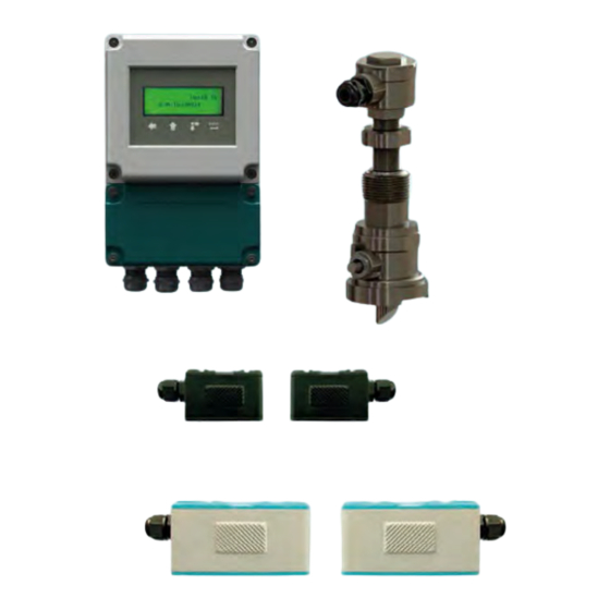
DI MPU01 Transit time ultrasonic lowmeter
Features
• Pipe dimension range:
• Transmitter protection class:
• Transducer protection class:
• Display: backlighted 2x20 alphanumeric digit
• Keypad:
• Housing material:
• Displayed data:
instantaneous flowrate;
• Mounting:
• Analog Output:
Sel. 4÷20mA or 0÷20mA
• Accuracy:
• Repeatability:
• Linearity:
• Basic measurement period:
• Serial port:
• Communication protocol:
• Programmable frequency output:
• Relay output: n.1 for pulse totalizer or alarm
• Medium speed range:
• Unit working temperature:
• Instrument humidity: non condensing 85% RH (40°C)
• Sensors working temperature:
TS-2/TM-1/TL-1 -30 ÷ +90°C
TS-2 HT/TM-1HT -30 ÷ +160°C
TC1/TLC-2 -40 ÷ +160°C
• Sensor cable std. length:
• Power s.: 230Vac or 10÷30Vdc (depending on model)
• Dimensions:
• Weight without sensors:
DN20 ÷ DN4000
IP66
IP68
4 keys
printing aluminium
flow totalizer
wall
±1%
±0,2%
±0,5%
500ms
RS485
MODBUS RTU
or ASCII+ (opt.)
0÷5000Hz
±12m/s
-20÷60°C
5m
200x120x77mm
1Kg
825B122A
Advertisement
Table of Contents

Summary of Contents for DI MPU01
- Page 1 DI MPU01 Transit time ultrasonic lowmeter 825B122A Features • Pipe dimension range: DN20 ÷ DN4000 • Transmitter protection class: IP66 • Transducer protection class: IP68 • Display: backlighted 2x20 alphanumeric digit • Keypad: 4 keys • Housing material: printing aluminium •...
-
Page 2: Working Principle
- Working principle The instrument is composed by a digital converter and two clamp-on or insertion type ultrasonic transducers. The instrument calculates the instantaneous flow rate value by measuring the flight time difference of the ultrasonic pulses. Compact system for conductive and Applicable to various pipes mate- non-conductive fluids, even with the r i a l s ( e g . - Page 3 - Features 2. FEATURES Carbon Steel; Stainless Steel; Cast Iron; Ductile Iron; Copper; PVC; Aluminium; Material Asbestos; FiberGlass-Epoxy; Other 20÷4000mm Pipe Ø range None, No Liner; Tar Epoxy; Rubber; Mortar; Polypropylene; Polystyrol; Polysty- Pipe Inner lining rene; Polyester; Polyethylene; Ebonite; Teflon; Other Upstream pipe straight section of 10÷40D.
- Page 4 - Transducers 3. TRANSDUCERS Transducer Type Caratteristiche Dimensions TS-2 20÷100mm (¾” ÷ 4”) Pipe Ø range -30 ÷ +90°C Temperature >19. Clamp-On TS-2 Menu 23 Dimensions TS-2-HT 20÷100mm (¾” ÷ 4”) Pipe Ø range -30 ÷ +160°C Temperature >19. Clamp-On TS-2 Menu 23 Dimensions TM-1...
- Page 5 - Transducers Transducer Type Caratteristiche Dimensions TL-1 300÷4000mm (3” ÷ 160”) Pipe Ø range -30 ÷ +900°C Temperature >20. Clamp-On TL-1 Menu 23 Dimensions TC-1 (standard) 80÷4000mm (3” ÷ 160”) Pipe Ø range -40 ÷ +400°C Temperature 1.6Mpa (16bar) Max pressure >17.
-
Page 6: Electrical Connections
- Dimensions/Electrical connections Fig. 2 5. ELECTRICAL CONNECTIONS 5.1 Connections 1) Separate the engine control cables or power cables from the DIMPU connection cables. 2) Remove the caps from the cable glands and open the cover by unscrewing the screws. 3) Lead the cables into the transmitter through the cable glands 4) Close the cap and tighten the cable glands Fig. - Page 7 - Electrical connections 5.2 Recommendations for external mounting - or electrical connections, use a cable with a 6÷10mm outer diameter and fully tighten the M18 cable gland - Securely close the cover - position the cable so that it forms a downward curve at the M18 output (Fig.4); in this way the condensation and/or rain water will tend to drop from the curve bottom - place the transparent cover for protection 5.3 POWER CONNECTION...
- Page 8 - Electrical connections 5.3.2 Supply voltage in 10÷30Vdc Fig. 6 5.4 TRANSDUCER CONNECTION Fig. 7 Pag. 8 of 52...
- Page 9 - Electrical connections 5.5 OUTPUT SIGNALS CONNECTION 5.5.1 Analog output Fig. 8 5.5.2 Pulse output Fig. 9 Pag. 9 of 52...
- Page 10 - Electrical connections 5.5.3 Relay output Fig. 10 5.5.3 MODBUS port Fig. 11 Pag. 10 of 52...
- Page 11 - Introduction 6. INTRODUCTION The instruement flow measurement system is composed of a digital converter and two ultrasonic transducers. The instrument uses the fluid transit time, measured inside a pipe of cylindrical section, to calculate the instantaneous flow rate value. The DSP technology, Digital Signal Processing, ensures system low sensitivity to any potential interference factors .
-
Page 12: Installation
- Installation 7. INSTALLATION 7.1 Measuring point Selection The transducers must be mounted on a pipe section which allows to respect the minimum distance between the element of resistance to flow, such as curves or derivations, and the measuring point. See the following table Tab. - Page 13 - Installation In the case of a horizontal pipe, the transducers positioning should be between ± 45 ° relative to the horizontal center line of the pipe. This is to avoid that any air bubbles can interfere with the flow velocity detection, Furthermore, in the case of buried pipe must observe the following measures: with insertion type transducers L>600mm;...
- Page 14 - Installation 7.3 V installing Is the installation method for pipes with diameters in the DN50÷250 range Fig. 20 7.4 Z installing Is the installation method for pipes with diameters in the DN300÷400 range Fig. 21 7.5 W installing Is the installation method for pipes with diameters in the DN20÷50 range Fig.
- Page 15 - Installation 7.6 Insertion transducer installation Steps required for proper installation: 1 - with encased pipe, check that there is the minimum space required for the transducers installation (fig.23) 2 - with encased pipe, check that the free section length of the pipe is the minimum required (fig.24) Fig.
- Page 16 - Installation 1) Weld or fix the valve base on the pipe (2 in figure 27). 2) Screw the ball valve (3 in figure 27) and tighten to ensure the seal. The valve must be opened 3) Insert the drill bit in the ball valve and tighten the seal gland (6 in figure 28) on the male threads (4 in figure 27),so that there is no leakage.
-
Page 17: Installation Check-Up
- Installation 3) the inclined surfaces of the ultrasonic transducer signal emitter (1 in figura 27) should be directed towards each other Fig. 31-a Proceed to the electrical connection Fig. 32 7.7 Installation check-up The signal reception power and quality (Q) can be checked through the installation check-up and it’s possible to make the comparison of the measured flight time by the measuring range depending on the pipe diameter. - Page 18 - Pipe Specifications 7.7.4 - Time ratio between the Measured Total Transit Time and the Calculated Time - M91 The value should be in the range 100±3%. If the value exceeds this range check: (1) That the parameters have been entered correctly (2) That the distance between the two transducers is the same as indicated in the menu M25 (3) That the transducers are installed in the right direction.
- Page 19 - Transducers positioning 9. TRANSDUCERS POSITIONING 9.1 Positioning type Selecting The transducers positioning type selection, Z-Mode, or V-Mode or W-Mode, is a function of measuring pipe DN: - recommended installation: W (small pipe) DN20÷50 DN50÷250 - recommended installation: V DN250÷4000 - recommended installation: Z 9.2 Marking positioning After the pipe parameters and transducers positioning type programming, the conversion unit automatically calculates the mounting axial distance between the two transducers: M25, Transducer Spacing.
- Page 20 - Transducers positioning 2) remove the paper roll and fold in half the portion corresponding to the circumference. Reposition the paper roll, so as previously folded, on the pipe and draw a straight line, called “S”, perpendicular to the “r” circumference line.
- Page 21 - Transducers positioning 9.3.1 - V or W mounting mode For the transducers correct positioning, proceed as follows: 1) as in step 9.3.1 1) 2) as in step 9.3.1 2) 3) now mark the “c” point on the “S” straight line, at a distance from “A” point equals the “Lout” measure previously calculated and displayed by the conversion unit in M25.
-
Page 22: Programming Menu Table
- Configuration 10. CONFIGURATION 10.1 Programming menu table M00 Instantaneous flow rate and total net displaying M53 AL5 analog input displaying M01 Instantaneous flow rate and velocity displaying M54 OCT output pulse width programming M02 Instantaneous flow rate and forward tot. displaying M55 Analog output mode programming M03 Instantaneous flow rate and reverse tot. - Page 23 - configuration 10.2.2 - tab. 6 legend: Available only with 9 option selected in M15 (**) Available only with 11 option selected in M16 (***) Available only with 8 option selected in M20 10.2 Quick Setup Guide 10.2.1 - How to evaluate if the instrument is working properly If in the display upper right, the ‘R’...
- Page 24 - Configuration 10.2.11 - How to use the integrated data logger Use the menu M50 to activate the data logger and to select items. Use the menu M51 to set the start time, interval time and the recordings number. Use the menu M52 for sending data. The default setting is sending data via RS485 10.2.12 - How to use the frequency output The output frequency signal represents the instantaneous flow rate value and is used for connection with other instruments.
- Page 25 - Configuration 10.2.15 - How to use acoustic alarms (Buzzer) The Integrated Buzzer is user settable. Can be used as an alarm. M77 for setting. 10.2.16 - How to use the OCT output (Open Collector) The OCT output is user settable via M78. Make sure that the frequency or pulse output supports the OCT.
-
Page 26: Programming Menu
- Programming menu 11. PROGRAMMING MENU 11.00 M00 - Instantaneous flow rate and total net displaying Displaying only. The display shows the instantaneous flow rate and net totalizer value. The “ R” symbol indicates that the transducers echo signal H” symbol indicates that the transducers echo signal quality is good; The “ quality is insufficient to ensure the correct flow measurement . - Page 27 - Programming menu 11.09 M09 - Daily totalizer displaying Displaying only. The display shows the daily flow totalizer. 11.10 M10 - Pipe outer circumference programming The display shows the previously set value. By entering a new value, the system will automatically calculate the pipe outer diameter new value (M11). 11.11 M11 - Pipe outer diameter programming The display shows the previously set value.
- Page 28 - Programming menu 11.16 M16 - Pipe inner lining material programming The display shows the previous setting. The available materials are: None, No Liner Tar Epoxy Rubber Mortar Polypropylene Polystyrol Polystyrene Polyester Polyethylene Ebonite 10. Teflon 11. Other (the 11 option actives M17 for the sound speed in the lining material) 11.17 M17 - Inner lining material sound velocity progr. (**) The display shows the previously set value.
- Page 29 - Programming menu 11.21 M21 - Fluid sound velocity programming (***) The display shows the previously set value. (***) Available only with 8 option selected in M20 11.22 M22 - Fluid viscosity programming (***) The display shows the previously set value. (***) Available only with 8 option selected in M20 11.23 M23 - Transducers type programming The display shows the previous setting.
- Page 30 - Programming menu 11.26 M26 - Data storage mode programming The display shows the previous setting. Available settings: Use RAM Settings (recommended); all the latest programming changes are automatically stored in the EEPROM SALVA PAR. IMPOSTAZIONI; to store in the EEPROM the latest changes to any menu, must go back to M26 and press 11.27 M27 - Default settings library...
- Page 31 - Programming menu 11.29 M29 - Empty pipe condition threshold programming The display shows the previous setting. This threshold is related to the Q value (see M90). When the Q value will be lower than the threshold value, set here, DIMPU activates the empty pipe condition by zeroing the flow measurement.
- Page 32 - Programming menu 11.34 M34 - Net totalizer activation programming The display shows the previous setting. To activate the net totalizer, between the forward totalizer and reverse totalizer, need to set “ON” Available settings: ON; OFF 11.35 M35 - Forward totalizer activation programming The display shows the previous setting. To activate the forward totalizer need to set “ON”...
- Page 33 - Programming menu 11.39 M39 - Language menu programming The display shows the previous setting. Available settings: English Italy 11.40 M40 - Damping programming The display shows the previous setting. In this menu it’s possible to change the damping value, in seconds. Range: 0÷9990 Sec 11.41 M41 - Low flow cut-off programming The display shows the previous setting.
- Page 34 - Programming menu 11.47 M47 - Protection password programming In this menu it’s possible to set a password to protect the system from tampering or other. To store a new password and protect the system proceed as follows: press Change the digit with and move the cursor to the right with , max.
- Page 35 - Programming menu Energy NEG Totalizer Analog Input 3 Flow Today Fluid Velocity Analog Input 4 Serial Number RTD T1 Analog Input 5 RTD T2 Working Timer 11.51 M51 - Data logger timer programming In this menu it’s possible set the timer data logger timer. To set the timer, proceed as follows : press Set the data logger start time.
- Page 36 - Programming menu 11.55 M55 - Analog output mode programming In this menu it’s possible to set the analog output mode. Default value: 0. 4-20mA Available settings: 4-20mA 0-20mA 0-20mA via RS232 (RS485) 4-20mA vs.Sound 20-4-20mA 0-4-20mA 20-0-20mA 4-20mA vs.Vel. 4-20mA vs.Energy 11.56 M56 - 4mA (or 0mA) output programming In this menu it’s possible to set analog output scale beginning.
- Page 37 - Programming menu 11.62 M62 - Serial port configuration programming In this menu it’s possible to set the serial port configuration. The default settings are: Baudrate 9600 Parity None Data Bits Stop Bits 11.63 M63 - Communication protocol programming In this menu it’s possible to set the communication protocol mode. Default setting: MODBUS RTU Only Available settings: MODBUS RTU Only...
- Page 38 - Programming menu 11.71 M71 - LCD contrast programming In this menu it’s possible to set the LCD contrast. Range: 00÷31 Press to enter, then increase the contrast with the decrease the contrast with Press to store 11.71 M72 - Operation time displaying In this menu it’s possible to display the DIMPUoperation total time, since the last timer reset.To reset the timer, proceed as follows: Press...
- Page 39 - Programming menu 11.78 M78 - OCT output programming In this menu it’s possible to set the function associated to the OCT digital output. Available settings: No Signal 14. Energy NET Pulse Poor Signal 15. MediaVel=>Thresh Not Ready (No *R) 16.
- Page 40 - Programming menu 11.81 M81 - Batch volume programming In this menu it’s possible to preset the batch volume value. To preset the batch volume proceed as follows: press Set the predetermined volume. Change the digit with and move the cursor to the right with Press to store.
- Page 41 - Programming menu 11.84 M84 - Heat meter unit programming The display shows the previous setting. Available settings: 0. Giga Joule (GJ) 1. Kilocalorie (Kc) 2. KWh 3. BTU 11.85 M85 - Temperature sensor input programming In this menu it’s possible to select the supply and return temperatures source. 11.86 M86 - Specific heat programming The display shows the previous setting.
- Page 42 - Programming menu 11.91 M91 - TOM/TOS % displaying In this menu it’s possible to display the ratio between the calculated and the measured transit time. Normally the value should be 100 ±3%. Differences in excess of the above, could mean improper transducers mounting, or incorrect programming values.
- Page 43 - Programming menu 11.98 M+3 - Last measured flow rate displaying In this menu it’s possible to display the last measured instantaneous flow rate value. 11.99 M+4 - DIMPU on/off times number displaying In this menu it’s possible to see how many times the unit DIMPU has been switched on and off .
- Page 44 - Main parameters description 12. MAIN PARAMETERS DESCRIPTION Name Displaying Description Menu Pipe Ø Pipe Outer Diameter Pipe Outer diameter (Pipe cross section) Pipe thickness Pipe Wall Thickness Pipe thickness (Pipe cross section) Carbon Steel; Stainless Steel; Cast Iron; Ductile Iron; Copper; Pipe material Pipe Material PVC (Plastics in general);...
- Page 45 - Main parameters description Name Displaying Description Menu The transducers may be mounted on the pipe in 4 different methods: V; Z; N; W and V. Transducers Transducer The mounting method mounting Mounting choice is in application con- method ditions function. The most frequently used mounting methods are V and Z.
- Page 46 - Main parameters description Name Displaying Description Menu The damping time defines the displayed flow measurement re- fresh rate in relation to the detected flow measurement variation. Range: 0÷9990 seconds Damping time Damping When the measured flow velocity is less than the cutoff value, the display will show the instantaneous flow rate measure at fixed 0.
- Page 47 - Main parameters description Name Displaying Description Menu The system protection password is used to prevent program- System protec- System Lock ming modification, or to not allow resetting totalizers. tion password NB - write down your password Is possible toset the digital pulse width during the counting. Range:0.01÷500ms OCT output pulse OCT Pulse Width...
-
Page 48: Troubleshooting
- Troubleshooting 12. TROUBLESHOOTING 12.1 Error messages and corrective actions The instrument has a self-diagnosis system which detects hardware problems. The instrument will show “*F” in the top left corner of the display and it will be necessary to power on again the DIMPU in order to see the error message and the solution: Error message Cause... -
Page 49: Error Codes And Solutions
- Troubleshooting 12.2 Error codes and solutions When the instrument detects an operating error, a letter will appear on the top left corner of the display. In M00 , M01, M02 , M03 , M90 and M08 can be displayed the error message. Refer to the following table for the solution: Tab. -
Page 50: Communication Protocol
Return flow rate per minute ±d.ddddddE±dd(CR) LF DQS(CR) Return flow rate per second ±d.ddddddE±dd(CR) LF DV(CR) Return flow velocity ±d.ddddddE±dd(CR) LF DI+(CR) Return POS totalizer ±dddddddE±d(CR) LF ** DI-(CR) Return NEG totalizer ±dddddddE±d(CR) LF DIN(CR) Return NET totalizer ±dddddddE±d(CR) LF... - Page 51 CRC check sum, which is the adding sum of the original character string. Take the DI+(CR) command as an example. Assume that DI+(CR) would return +1234567E+0m3(CR)(LF)( the string in hexadecimal is 2BH, 31H, 32H, 33H, 34H, 35H, 36H, 37H, 45H, 2BH, 30H, 6DH, 33H, 20H, 0DH, 0AH) , then PDI(CR) would return +1234567E+0m3!F7(CR)(LF).
- Page 52 Documentation subject to technical change with no prior warning...
Need help?
Do you have a question about the MPU01 and is the answer not in the manual?
Questions and answers