Table of Contents
Advertisement
Quick Links
Advertisement
Table of Contents

Related Manuals for Furukawa electric S124


Summary of Contents for Furukawa electric S124
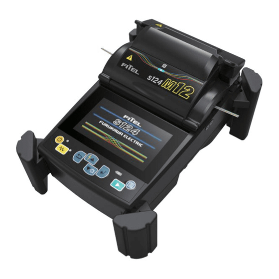
- Page 1 FTS-B557-01 S124 FUSION SPLICER USER MANUAL Issue 1...
-
Page 2: Table Of Contents
Safty information and instructions _________________________________ 4 Safety Information ________________________________________________ 4 Safety Messages___________________________________________________ 4 WARNINGS and CAUTIONS _______________________________________ 5 Power Requirements ______________________________________________ 11 Toxic Hazards ____________________________________________________ 12 1.5.1 Incineration ______________________________________________________ 12 1.5.2 Acidic or caustic compounds _______________________________________ 12 1.5.3 Physical damage _________________________________________________ 12 Getting Started _________________________________________________ 13 Unpacking and Initial Inspection __________________________________ 13 Operating Specifications and Components _________________________ 14... - Page 3 Fusion Splicing __________________________________________________ 33 Arc Check _______________________________________________________ 33 Preparing the Fiber_______________________________________________ 36 6.2.1 Loading the Fiber _________________________________________________ 37 6.2.2 Using the Fiber Reformer __________________________________________ 40 Fusion Splicing __________________________________________________ 41 6.3.1 Splicing Defects __________________________________________________ 44 6.3.2 Removing the Spliced Fiber ________________________________________ 45 6.3.3 Reinforcing the Fusion Splice ______________________________________ 45 Menu ___________________________________________________________ 48...
- Page 4 Installing the Battery ______________________________________________ 99 Backup Battery _________________________________________________ 100 Storing and Shipping ____________________________________________ 100 Claims and Repackaging _________________________________________ 100 Return Shipments to Furukawa Electric Co., LTD. __________________ 101 Optional Components ___________________________________________102 Battery Charger :S980 ___________________________________________ 102 Spare Battery: S947 _____________________________________________ 102...
-
Page 5: Safty Information And Instructions
1.1 Safety Information The following safety instructions must be observed during the operation, service or repair of the S124 fusion splicer. Failure to comply with any of the instructions or warning contained in the User’s Manual is a direct violation of the design, manufacture and intended standard use of the instrument. -
Page 6: Warnings And Cautions
Please contact Furukawa Electric Co., Ltd. or your local representative with any questions relating to any subject described within this manual. In no case will Furukawa Electric Co., Ltd. be liable to the buyer, or to any third parties, for any consequential or indirect damage which is caused by product failure, malfunction, or any other problem. - Page 7 If abnormal sounds or extra high temperatures are observed, turn off the power, disconnect the power cord, remove the battery from the fusion splicer, and contact Furukawa Electric Co., Ltd. or your local representative. Continued operation under these conditions may cause fire or electric shock.
- Page 8 External Impact resistance – IK07 rating external impact proof (exposed to 500g weight dropping from 40cm height) Above tests were performed at Furukawa Electric laboratories and do not guarantee that the machine will not be damaged when subjected to these conditions.
- Page 9 Do not short-circuit the recharging connector or the output terminal of the splicer. Doing so may cause fire. Charge the S947 battery by using the S124. Charging using other equipment that is not suitable for charging the S947 battery, may...
- Page 10 Disposal of used batteries must be carried out according to disposal regulations established by law. For instructions, contact Furukawa Electric Co., Ltd. or your local representative. NOTES This symbol mark is for EU countries only.
- Page 11 This device complies with part 15 of the FCC Rules. Operation is subject to the following two conditions: (1) This device may not cause harmful interference, and (2) this device must accept any interference received, including interference that may cause undesired operation.
-
Page 12: Power Requirements
Cet appareil numérique de la classe B est conforme à la norme NMB-003 du Canada. 1.4 Power Requirements The S124 fusion splicer can also operate from an AC power source with the S979 AC/DC adapter. The S979 adapter can accept an AC power source with voltage between 100~240V at a frequency of 50~60Hz. -
Page 13: Toxic Hazards
1.5 Toxic Hazards The S124 fusion splicer presents no toxic hazards (under normal conditions of use, storage, and handling). However, under the following conditions, certain precautions are necessary. 1.5.1 Incineration Some of the electronic components included in the assembly are constructed with resins and other chemicals that produce toxic fumes during incineration. -
Page 14: Getting Started
4. Inspect the contents to ensure that the shipment is complete. 5. Lift the S124 fusion splicer out of the carrying case, and place the instrument on a flat, smooth surface. 6. Visually inspect the S124 fusion splicer and all accompanying components for structural damage that may have occurred during shipping. -
Page 15: Operating Specifications And Components
3. Operating Specifications and Components 3.1 Specifications The specification of S124 splicer is listed in the following table. Item Specification and Features Applicable fibers* SMF / MMF / DSF / NZDSF Fiber count Single fiber and 2, 4, 6, 8 10, 12-fiber... - Page 16 *3: Tested in a laboratory environment with similar fibers. Not guaranteed results. *4: Wen operating with the battery, the heating time might be longer than typical heating time. The heating time may increase depending on the environmental conditions. *5: The heating time may increase depending on the sleeves used.
-
Page 17: Components
3.2 Components 3.2.1 Standard Components The S124 Fusion Splicer comes with the following items as standard. Confirmation of their presence is advised before operation. The components along with their order reference number are shown below. Components Model Number S124 Main Body... - Page 18 Components Model Number Working Belt WBT-01 Fiber Holder for 250μm S712S-250 1pair Fiber Holder for 500μm S712S-500 1pair Fiber Holder for 900μm S712S-900 1pair Fiber Holder for 2-fiber ribbon S712A-002 1pair Fiber Holder for 4-fiber ribbon S712A-04e 1pair Fiber Holder for 6-fiber ribbon S712A-006 1pair Fiber Holder for 8-fiber ribbon...
-
Page 19: Optional Accessories
S924 40mm Splice length Protection Sleeves for ribbon fiber S927R 40mm Splice length Protection Sleeves for ribbon fiber 3.4 Recommended Consumables Keep a supply of the following items with the S124 fusion splicer at all times. Tweezers ... -
Page 20: External Description
4. External Description 4.1 Main Body Protection Sleeve Heater LCD Monitor Operation Keys Windshield Battery Cover mini-B Port DC Power (For PC) Port Electrode V-Groove Fiber Clamp... -
Page 21: Operation Keys And Status Led
4.2 Operation Keys and Status LED 4.2.1 Operation Keys Indicator Name Main Functions Start Start / Pause / Restart the splicing process Escape Cancel the current action. Enter Select the menu item / Determine the value Move upward / Add additional arc Move downward / LCD Brightness control Down when ready status... -
Page 22: Buzzer
Indicator Name Color Main Functions Lit : During heating Heater LED Blinking : During cooling Lit: During charging Charge LED Orange Blinking: Error 4.2.3 Buzzer A buzzer will ring whenever any key is pressed. In addition, the following buzzer patterns indicate status of operation. ... -
Page 23: Heater
4.3 Heater The S124 has several heater programs that are made for different types of protection sleeves. There is a switch for fast heating, located under the heater lid. It is important to set this switch to the position appropriate for the heater program selected. -
Page 24: Screens
4.4 Screens 4.4.1 Ready Screen Once the S124 fusion splicer is powered up and initialized, the “Ready” screen is displayed. 4.4.2 Screen during Splice Fiber Image X from front camera and Y from back camera. X and Y views can be switched by touching the X/Y icon. -
Page 25: Status Icons
4.4.3 Status Icons Type Icon Content The level of the battery is displayed in a percentage next to the battery icon. Battery status Battery is not installed. Charging battery. Using external power. Connected to the PC. USB storage device is connected. System status Wi-Fi available (Not connected to AP) -
Page 26: Basic Operation
5. Basic Operation 5.1 Preparations for Power Supply 5.1.1 Connecting the power cable to the AC the adapter Connect the AC adapter to the DC Power port of the Splicer, and plug the AC adaptor into an AC outlet. AC Adapter 5.1.2 Charging the Battery After connecting the power cable to the AC adapter and plugging the power cable into the AC outlet, the charging process starts. -
Page 27: Turning The Splicer On And Off
S947 battery is a lithium ion type rechargeable battery; it can be recharged at any time, regardless of its current capacity (empty or still with some residual power). If storing the battery for a long time, the power level will becomes very low due to self-discharging and the battery may degrade. - Page 28 Turning OFF power The LCD screen is turned off. The power supply cuts after all motors have performed the reset operation.
-
Page 29: Load Programs
5.2 Load programs Install appropriate programs before operation. The S124 fusion splicer already has pre-defined programs installed for major fiber types and protection sleeves. Select the program for fusion and heat, or edit and store a new program. 5.2.1 Fusion Program Install an appropriate fusion program for specific fibers to be spliced. - Page 30 Mode Comment Applied fiber AUTO Booked for expansion Booked for expansion Booked for expansion SM12 SINGLE MODE SM12-fiber standard fiber SM10 SINGLE MODE SM10-fiber standard fiber SINGLE MODE SM8-fiber standard fiber SINGLE MODE SM6-fiber standard fiber SINGLE MODE SM4-fiber standard fiber SINGLE MODE SM2-fiber standard fiber SINGLE MODE...
-
Page 31: Heater Program
2. Select the proper program by pressing ▲ ▼ key. 3. Tap the heater program to install the heater program. When the S124 is turned on, the last program used is selected automatically. The curl-remove program can be selected from the heater program menu. -
Page 32: Selecting The Operating Language
S921 DC without pre-heat 5.2.3 Selecting the Operating Language The S124 fusion splicer can be set to provide operating prompts in several languages. The default operating language is English. 1. In the Ready screen, press key to access the menu screen. - Page 33 2. Select “Setting”. 3. Select “Language” by pressing ▲ ▼ key. 4. A pop-up window shows the current language. Select your language by Pressing ▲ ▼key. 5. Press key and the pop-up window will confirm the change. Select “Yes” to confirm the change, or “No” to cancel the operation. 6.
-
Page 34: Fusion Splicing
1. Open the windshield and load the prepared fibers. Ensure that the fibers are properly stripped, cleaned and cleaved. 2. Close the windshield. 3. Select “Arc Check”. 4. The S124 fusion splicer automatically feeds the fibers and discharges the arc. - Page 35 The environment compensation is performed based on the time when arc check is performed and passed. The arc check function inspects how far the fibers melt back and the centered position of the fiber. If the arc check results are good, the message “Result OK”...
- Page 36 either cleaning or replacing. Pressing key after the arc check, displays the detailed arc check data. Ave. Retreat Min., Max. Retreat Min., Max. Retreat spec Current and suggested arc power Current and suggested arc center If the arc check result data output setting is OFF, the above screen will be displayed after the arc check.
-
Page 37: Preparing The Fiber
6.2 Preparing the Fiber Splice loss is directly affected by the quality of the fiber preparation. For the best results, ensure that the V-grooves are clean and that the fiber ends are properly cleaned and cleaved. Prepare a single fiber according to the following procedure. 1. -
Page 38: Loading The Fiber
4. Cleave the fiber so a proper length of bare fiber extends past the fiber coating (depending on the fiber holder type). Refer to the manual of the cleaver for the details. Do not clean the bare fiber after it has been cleaved. ... - Page 39 When performing a dissimilar fiber splice, the orientation of the fibers is of no concern. Either fiber can be placed on the left or right side of the S124. When setting loose tube fiber, aim to clamp the fiber part by the inside clamp of the holder lid and to clamp the tube part by the outside clamp of the holder lid.
- Page 40 V-groove. In such case, it might be better to put the fiber edge in a downward direction (flip fiber with 180 degree). S124 has 12 V-grooves. Fiber into the first V-groove as shown the figure. V-groove number...
-
Page 41: Using The Fiber Reformer
6.2.2 Using the Fiber Reformer Use the Fiber reformer when the fiber has severe curl preventing the fiber from resting correctly in the V-groove. Prepare fiber in fiber holder per normal procedure. Put the fiber reformer on the fiber holder, the guide of reformer makes contact with the fiber coating. -
Page 42: Fusion Splicing
3. The S124 fusion splicer performs the following functions automatically. To pause the S124 fusion splicer during any of these functions, press . The message PAUSE will be displayed on the monitor. To restart the operation, press again. - Page 43 4. While in Pause status, pressing displays options available in the process. To resume the process, press Screen Capture: Capture the fiber image and store it. Fiber Measurement: Performs an auto or manual inspection of the fiber with regards to clad and core offset, relative eccentricity, gap, fiber tilt and relative cleave angle.
- Page 44 fibers after READY is displayed and retry the splice by repeating the entire procedure, starting from the fiber preparation process. To ignore the error and continue the cycle, press “Continue” or press key. After splicing, the splicer inspects the splice state by image processing.
-
Page 45: Splicing Defects
appropriate error message is displayed as below. ▼ key, an error massage will be un-displaying and you will be able to see the state of fiber. Open the windshield, remove the fibers after READY is displayed and retry the splice by repeating the entire procedure, starting from the fiber preparation process. -
Page 46: Removing The Spliced Fiber
Handle the spliced fiber carefully. Do not twist the fiber. CAUTION Do not attempt to load fibers while the S124 fusion splicer is resetting. Load the fibers only after the reset operation is complete and the READY screen is displayed. - Page 47 3. Heater cover closes automatically. 60mm S921 40mm S922 S924 S927B 20mm S928A-20 25mm S928A-25 35mm S928A-35 If protection sleeve is placed in the incorrect position when heating, this may cause a shrinking error. 4. When the fiber is set and the heater cover is shut, the heat LED turns on red and the heating starts automatically.
- Page 48 Type Icon Content Cooling Mode Error Occurring To stop the heating operation (when the HEAT LED is lit), press . The heating will stop immediately. When the ambient temperature is lower than 10°C, the heating time is automatically extended by approximately 5 to 20 seconds. During the heating cycle, do not open the heater clamp or lid.
-
Page 49: Menu
WARNING STOP using the fusion splicer when problems are experienced with the protection sleeve heater. Turn off the power immediately, disconnect the power cord, remove the battery, and contact your local service center. DO NOT touch the heater element during the heater cycle and right after the heating process is completed. - Page 50 The following table is a list of functions available to the operator for customization programming and maintenance. Menu Features Contents Automatically diagnose condition of Self-Check machine. Measure and indicate fiber’s clad Fiber diameter, core diameter, core offset Measurement between fibers, cleaving angles and/or gap between fibers.
- Page 51 Menu Features Contents Previous splice data. Splice History Arc Check Previous arc check data. History Captured Manually captur fiber image. Image Data Failure History Splicing data failure history. Check arc intensity and automatically Perform arc optimize to a proper level. See "Arc check Check, Getting Started".
-
Page 52: Programming Function
6.5 Programming Function To start a program, the user needs to access each function through the program selection screen. Tap the program area on the touchscreen, or select “Fusion Program / Heater Program” in the menu screen. Fusion Program Heater Program... -
Page 53: Program Edit
6.6 Program Edit 1. Select “Fusion Program” or “Heater Program” menu. The following procedures and pictures are for Fusion program editing; however, the same procedure can be applied to the Heat programs. 2. Select a program to be modified by pressing or pressing and to access to pop-up menu. -
Page 54: Edit
6.6.1 Edit 1. Select “Edit” in the pop-up menu. 2. Select the parameter to change with ▲ ▼ key. 3. Edit Parameter or name. Program where the key icon is displayed cannot be edited. 4. Press “OK” button or key. 5. -
Page 55: Copy & Paste
2. A more detailed set of parameters is available. The setting method is the same as "Edit". Press : Move to previous page. Press : Move to next page. 6.6.3 Copy & Paste Follow the procedures shown below to copy the selected program. 1. -
Page 56: Default
1. Select “Delete” in the pop-up menu. 2. Select “Yes” or press key to delete program. Otherwise select “No” or press key to cancel the operation. The factory pre-installed programs cannot be deleted. If the current program is deleted, No.001 program will be selected. -
Page 57: Export
6.6.7 Export Follow the procedures shown below to export a program to external storage. Exported data is able to be import to another S124 splicer. 1. Open the battery cover. 2. Connect the storage device into USB A connector. -
Page 58: Parameter Table
two programs. 1. Select “Compare” in the pop-up menu. 2. Select the program to compare. 3. The parameters of two programs are displayed. Item name is displayed in red if parameter is different. 6.6.9 Parameter Table Parameter Table for Splice Parameter Name Unit Description... - Page 59 Parameter Name Unit Description Pull back distance from the final overlapping Z Pull Length µm position. ON duration of pulse arc discharge in 2 Pulse ON Time discharge. OFF duration of pulse arc discharge in 2 Pulse OFF Time arc discharge. Attenuation Function to allow attenuation splicing.
- Page 60 Time chart of fusion parameters Time flow Collision of Fibers 1st Arc 2nd Arc Arc Power 2nd Arc Start 1st Arc End Power Power 2nd Arc End 1st Arc Start Power Power 1st Arc Duration 2nd Arc Duration Z Distance Feeding Z Push Length Z Pull Length PreArc Duration...
- Page 61 Parameter Table for Heater Program Parameter Unit Description Heat Temp IN °C Temperature of INNER heater for the first half. Heat Temp OUT °C Temperature of OUTER heater for the first half. Heat Duration Operation time of the first half. Heat Temp IN °C Temperature of INNER heater for The latter half.
- Page 62 Time chart of heater parameters Temperature Heat Temp. IN Heat Temp. IN Heat Temp. OUT Heat Temp. OUT Pre Heat Temp. IN Cool Temp. Pre Heat Temp. OUT Heat Time Heat Time Pre Heat Time Time INNER Heater OUTER Heater...
-
Page 63: Tool Menu
1. A pop-up message prompts the user to remove the fiber from the machine. Follow the messages and press “Continue” or key. 2. The S124 automatically checks for dust on the camera and verifies the motor movements. A Pop-up screen then prompts the user to set the fiber in place. -
Page 64: Fiber Measurement
When executing the "Self Check” function, please use fibers that have been stripped, cleaned and cleaved correctly. 6.7.2 Fiber Measurement The S124 performs an auto or manual inspection of the fiber (specifically, the clad and core offset, relative eccentricity, gap, fiber tilt and relative cleave angle). -
Page 65: Manual Splice
6.7.3 Manual Splice Manual splice enables the entire splicing process to be operated manually using the keypad. 1. Select “Manual Splice” in the maintenance menu. 2. Select the preferred operating mode. Load fibers before selecting “Auto Feeding”. Manual: All operations are done manually following the procedures. ... -
Page 66: Shrink Sleeve Adjustment
ALN_X Activate X-axis aligning ALN_Y Activate Y-axis aligning Select high speed motor movement High Speed Select low speed motor movement Drive the motor step by step by pressing Free ▲▼key. Distance Motor moves based on pre-set value. (Value) Selections from: Z: 5/50/500 [µm] FCS: 0.5/5.0/50.0 ALN: 0.1/1.0/20.0... - Page 67 Bubbles in the sleeve center Fiber coating melts Sleeve melts too much Default to the factory setting 3. The heating condition is adjusted so that the shrinking condition for the sleeve becomes better. 4. If the adjustment is insufficient, repeat the above operation.
-
Page 68: Data Management Menu
6.8 Data Management Menu By selecting “Data Management” in the Menu screen, the user can access the detailed splice data, arc check history and archived images. 1. On the Menu screen, select “Data Management”. 2. Select “Splice History”, “Arc Check History”, “Captured Image”... - Page 69 Parameter Table for Splice History Data Title Description Arc Count Arc count when splice was performed. Date Date and time of when the splice was performed. Temperature Temperature when the splice was performed. Pressure Pressure when the splice was performed. Program name Name of fusion program.
-
Page 70: Arc Check History
6.8.2 Arc Check History 1. The list of previous arc checks is shown on the same screen as splice data. 2. Select a time period to display the detail of the data. 3. Press to display the detailed data of each fiber as follows. Parameter Table for Arc Check History Data Title Description... -
Page 71: Captured Image
Data Title Description Value of the centered position that the fibers have Arc Center melted back. The arc check data can be exported to an external storage. After attaching the storage, touch the icon or press key. 6.8.3 Captured Image 1. -
Page 72: Failure Data History
6.8.4 Failure Data History 1. The failure list is shown on the same screen as the splice data. 2. Select a time period to display detail of the failures as shown in the picture. Touching tab or pressing key will display the image before splicing and the image after splicing. -
Page 74: Information Menu
Machine-specific information such as serial numbers and version information is displayed. 6.9.2 Environment Information The S124 allows the user to view environmental conditions. 1. Select “Information” in the menu screen. 2. Touch the thermometer symbol or press key. The chamber temperature and atmospheric pressure are displayed. -
Page 75: Counter Information
6.9.3 Counter Information Touch the counter symbol or press key twice. Arc Count Displays arc count and alarm count of the arc discharge. The cleaning arc discharge is not included. The alarm count is set in the settings menu. This count can be cleared in the settings menu. -
Page 76: Maintenance Menu
6.10 Maintenance Menu This menu provides various kinds of maintenance functions. 6.10.1 Quick Guide The S124 allows the user to obtain procedures and pictures for maintenance. 1. Select “Quick Guide” in the maintenance menu. 2. Select an item from following list. -
Page 77: Update
3. Connect the storage device into USB A connector. 4. Select “Update” and select “Yes”. 5. The file is automatically copied. 6. You must restart the S124 after “Please re-start splicer” when displayed. 7. When the update is completed, remove the USB storage device and close the battery cover. -
Page 78: Regulatory
Delete the entire captured image record. Counter Reset Reset arc count and splice count. Total arc count and total splice count are not cleared. 6.10.5 Regulatory Display regulatory information of FCC and ICES. -
Page 79: Settings Menu
6.11 Settings Menu 1. Select “Settings” in the menu. 2. The parameter list and the current setting are displayed. Press ▲ ▼ keys to scroll through the available settings. 3. Press key after editing the parameter. 4. The pop-up menu will display up and ask to overwrite. ... - Page 80 Setting Item Contents Full auto/ step1/ step 2 Common Arc Power Set common arc power. Clamp up down when Clamp Up Down On/Off operation Clamp down just after close Clamp Buffer On/Off the canopy Set the arc power Arc Power Compensation compensation.
- Page 81 Setting Item Contents Pressure Unit Select the unit pressure. Select the pressure or Barometer / Altimeter altitude. Year Set the date and time. Month Hour Date and Time Minute Second Date Format Select the date format. 24 Hour Format Select the time format. Arc Count Alarm Set the count to alarm Total Arc Count Alarm...
-
Page 82: Language
6.11.2 Language Select the display language. 6.11.3 Auto Start Auto Start for Fusion Auto start function does not work. Semi Auto The fibers move to the center of the screen when the windshield is closed. After the fibers are set and they temporarily stop. -
Page 83: Stepping Action
Item Description GAP (um) The distance between left fiber and right fiber Clad offset before (um) Relative clad offset value between left fiber and right fiber Clad offset after (um) Relative clad offset value between left and right fiber 6.11.5 Stepping Action Select splice operation mode. -
Page 84: Tension Test
The center of the arc discharge is corrected automatically. The S124 has an automatic arc compensation function. However, due to some factors, such as the poor preparation of the spliced fiber, and some environmental factors, it may not always be fully functional. Therefore it is recommended to perform a manual arc check whenever the estimated and actual loss results become unsatisfactory. - Page 85 Time until switching to auto shutdown, can be set from 10 to 30 minutes. Screen Style Select the screen style from the following options: Dual Single X Single Y Reverse Monitor Select the direction of LCD screen.
-
Page 86: Sound
Touchscreen Disable the touchscreen. Camera Sleep The power consumption is reduced by stopping the camera when the windshield is opened 6.11.12 Sound Buzzer Volume Set Buzzer volume from 0 to 3. 0. (With 0 being silent.) Buzzer Tone Select the buzzer tone form High / Middle / Low. -
Page 87: Sensor
6.11.14 Sensor Temperature Unit Select the temperature unit from Celsius and Fahrenheit. Altimeter Select the unit of atmospheric pressure from hPa and mmHg. Pressure / Altimeter Convert the atmospheric pressure to altitude. This altitude is different from the actual altitude because it converts to altitude from atmospheric pressure simply. -
Page 88: Security
6.11.17 Security Password Lock Lock S124 by using a password. If activated you need to enter the password during the start-up process. Password Set password with 6-digit number. -
Page 89: Eco Charge
3. Select SSID to connect. SSID can be inputted manually. 4. Select “Password”. Input the password, and touch the “ENTER” key. 5. Press key twice. The pop-up menu will show up and ask to overwrite. To check the Wi-Fi connection, return to the Wi-Fi setup menu and confirm that the IP address is displayed 6.11.19 Eco Charge... -
Page 90: Error Messages And Maintenance
7. Error Messages and Maintenance 7.1 Error Messages The following is a list of major error messages that can be observed. Refer to the following table for trouble-shooting. Error Code Cause of Error Action Exceeding the inspection criteria for cleave Prepare the fiber again and Cleave Error quality... - Page 91 Spec Out Fiber program. (The fiber is out of Cladding diameter is out of applicable applicable range.) Cannot splice with S124. range. The position of the built-in camera has been Camera Position Error Contact service center. changed by a strong impact.
- Page 92 Error Code Cause of Error Action Check correct Incorrect parameter setting for MFD. parameters. Defect in the image processing system. Contact service center. The optics are dirties See maintenance chapter. HEATER ERROR Check correct Inappropriate heater program is selected. Failed to reach the parameters.
-
Page 93: Maintenance
When the Arc Counter number exceeds 5,000, the S124 automatically displays a message to prompt replacing the electrodes at when powered on (when The Counter Alarm is ON). The S124 asks whether to reset counter. Select “Yes” if replaced and “No” if not. When “Yes” is selected, the arc counter is reset to 0 and the message will not appear at power on. - Page 94 touch the electrode while the power is on. Longer arc durations used in dissimilar fiber splicing require the electrodes to be cleaned and replaced more often. Frequent electrode maintenance is recommended for dissimilar fiber splicing programs. 1. Loosen the screws of the electrode holder. The electrode is raised together with the electrode holder.
-
Page 95: Cleaning The Objective Lens
electrode sharpener and twist the electrode 3~4 times. Attention: Don’t grasp the electrode knob (if possible, grasp the mid-section of the rod). b) In an effort to clean the electrode tip, wipe it softly with BEMCOT covered in alcohol. < Attention > ... -
Page 96: Cleaning The V-Grooves
3. A dirty or damaged lens may prevent the splicer from performing a splice or may produce incorrect splice loss information. Cleaning is best performed once a month. Shorten the cleaning cycle interval if dirt is prominent. 7.2.4 Cleaning the V-grooves Dirt on the V-grooves or fiber clamps will offset the alignment of the fibers or cause stress points on the glass, making the fiber weak. -
Page 97: Cleaning The Tight-Holder And Fiber Holder
CAUTION The V-groove is made of a brittle ceramic material. Clean the V-groove carefully. DO NOT use any abrasive tools such as metal to clean. As Freon gas might contaminate camera lens, DO NOT use a spray including Freon gas or alternatives for cleaning. - Page 98 1. Remove the electrode fixing screw with electrode, electrode holder. 2. Remove the V-groove fixing screw by torque driver. V-groove fixing screw 3. Hold left back and right front corner and remove the V-groove. Left back side Right front side 4.
- Page 99 V-groove holding pin V-groove positioning notch 5. Tighten the V-groove fixing screw with 0.29N・m with torque driver. B 6. Fix the electrode screw with electrode and electrode holder. 7. Arc check again after fix the V-groove.
-
Page 100: Removing The Battery
7.3 Removing the Battery 1. Loosen the screws of the 2. Pull out the battery battery cover, and connector. remove the battery cover. 3. Remove the connector 4. Pull the battery straight in while pressing the latch. the battery slot of fusion splicer. -
Page 101: Backup Battery
Immediately inform Furukawa Electric Co., Ltd. or your local sales representative and, if necessary, the carrier, if the contents of the shipment are incomplete, or if the S124 fusion splicer or any of its components are damaged or defective. Likewise, if the fusion splicer fails during operation. -
Page 102: Return Shipments To Furukawa Electric Co., Ltd
Co., Ltd. customer service personnel. This number must be obtained prior to shipping any material back to Furukawa Electric Co., Ltd. The owner’s name and address, the model number and full serial number of the S124 fusion splicer, the RMA number, and an itemized statement of claimed defects must be included with the return material. -
Page 103: Optional Components
8.1 Battery Charger :S980 S980 battery charger for charging S947 battery. 8.2 Spare Battery: S947 Spare battery for S124. If the number of splices is significantly reduced, replace the battery. 8.3 Cleaning Brush: VGC-01 This brush is used to remove the dust and dirt that stick to the V-groove and fiber clamp. -
Page 104: Fiber Reformer: Frf-01
8.4 Fiber reformer: FRF-01 Fiber reformer is useful when fiber is severely curled and is hard to putt on the V-groove. Fiber reformer 1. Prepare fiber in fiber-holder by normal procedure. 2. Set the fiber reformer on the fiber-holder, the guide of reformer makes contact with the fiber coating. - Page 105 8. Move the reformer to guide the fiber into the proper V-groove. 9. When the fiber is in the proper V-groove, close the windshield leaving the reformer in place, then splice. 10. After splice, remove reformer, then remove fibers by opening the lid of fiber holders.
-
Page 106: Recycling And Disposal
S124 has a backup battery (lithium button cell battery) for backup calendar. How to remove the battery is indicated below. This should only be done at... - Page 107 Removing the built-in battery 1. Loosen the screws, and remove the battery cover. 2. Remove 8 screws, and remove the bottom cover. 3. Remove all wiring connected to the electric board. And remove 2 screws which fix the board. 5. There is a built-in battery in the back of the board. Take off the battery from its holder.
- Page 109 For sales and service information, Contact FURUKAWA ELECTRIC CO., LTD. Or your local representative. Fiber Optic Instrument Department FITEL Products Division Furukawa Electric Co., Ltd. 6, Yawata Kaigandori, Ichikawa, Chiba 290-8555 Japan TEL:+81-436-55-8175 FAX:+81-436-55-8174...
Need help?
Do you have a question about the S124 and is the answer not in the manual?
Questions and answers