Table of Contents
Advertisement
REFRIGERATOR
REFRIGERATOR
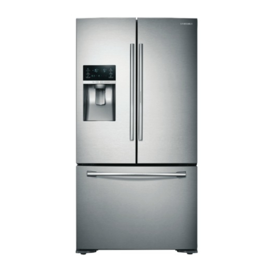
FRENCH DOOR REFRIGERATOR
BASIC : RF23HT*
MODEL NAME : RF23HTEDBSR
MODEL CODE : RF23HTEDBSR/EF
RF23HTEDBSR/EU
RF23HTEDBSR/EO
CONTENTS
1. PRECAUTIONS(SAFETY WARNINGS) ·······5
2. PRODUCT SPECIFICATIONS ······················9
3. DISASSEMBLY AND REASSEMBLY ·········25
4. TROUBLESHOOTING ································60
5. PCB DIAGRAM ········································· 111
6. WIRING DIAGRAM ··································· 116
7. BLOCK DIAGRAM ···································· 117
8. MODEL CODE TABLE ······························ 119
Advertisement
Table of Contents


Need help?
Do you have a question about the RF23HT Series and is the answer not in the manual?
Questions and answers