Table of Contents
Advertisement
Quick Links
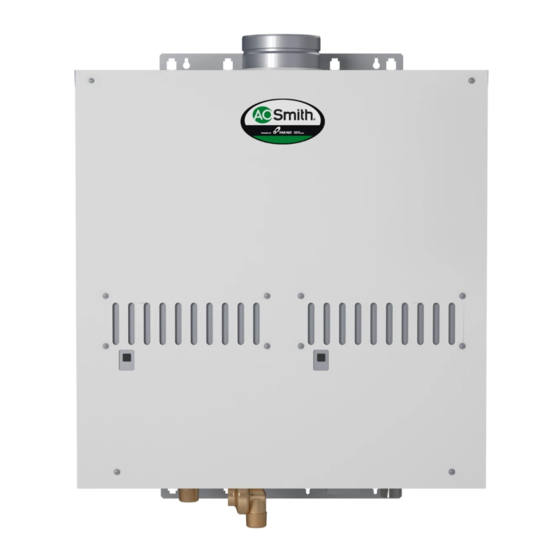
910 / 910 ASME
On-Demand Water Heater
Installation Manual and Owner's Guide
Gas Tankless Water Heater
910 / 910 ASME Models
Suitable for potable water heating and space-heating*
* Please refer to local codes for space-heating compliance.
FEATURING
• ENDLESS HOT WATER
• ON-DEMAND USAGE
• COMPACT, SPACE SAVING
• ENERGY CONSERVATION
• COMPUTERIZED SAFETY
• NO PILOT LIGHT
• EASY-LINK SYSTEM
This product must be installed
and serviced by a licensed
plumber, a licensed gas fitter,
or a professional service tech-
nician. Improper installation
and/or operation, or installation
WARNING
by an unqualified person, will
void the warranty
- Do not store or use gasoline or other flam-
mable vapors and liquids in the vicinity of this
or any other appliance.
- WHAT TO DO IF YOU SMELL GAS
• Do not try to light any appliance.
• Do not touch any electric switch, do not
use any phone in your building.
• Immediately call your gas supplier from a
neighbor's phone. Follow the gas suppli-
er's instructions.
• If you cannot reach your gas supplier, call
the fire department.
- Installation and service must be performed by
a qualified installer, service agency or the gas
supplier.
If the information in these
instructions is not followed
exactly, a fire or explosion may
result causing property dam-
age, personal injury or death.
WARNING
If you have any questions,
please call or write to:
GSW Water Heating
599 Hill Street West
Fergus, ON Canada N1M 2X1
Toll Free: 1-888-479-8324
320579-000
REV. 00 (11-04)
Advertisement
Table of Contents
Troubleshooting

Summary of Contents for Smith Water 910 ASME
- Page 1 If the information in these Gas Tankless Water Heater instructions is not followed exactly, a fire or explosion may 910 / 910 ASME Models result causing property dam- Suitable for potable water heating and space-heating* age, personal injury or death.
-
Page 2: Table Of Contents
Table of Contents SPECIFICATIONS ....... 3 INITIAL OPERATION ......18 INTRODUCTION . -
Page 3: Specifications
*40 psi or above is recommended for maximum flow 2. Flow sensor 3. Gas Valve 4. Temperature sensor NOTE * All references to the 910 also refer to the 910 ASME model Cold Water * Check the rating plate to ensure this product matches Inlet Hot Water... -
Page 4: Combustion Sections Within The 910
Combustion Sections Within The 910 SAFETY GUIDELINES Left combustion Right combustion section section Indicates an imminently hazardous situa- tion which, if not avoided, will result in death or serious injury. DANGER Indicates an imminently hazardous situa- tion which, if not avoided, could result in death or serious injury. -
Page 5: Installation
• The warranty will not cover damage caused by water quality. Water hard- ness that leads to scale formation and/or corrosion may affect/damage the water heater. Hard water scaling and/or cor- rosion must be avoided or controlled by proper water treatment. Rating plate •... -
Page 6: General
General Warning For Installations The manifold gas pressure is preset at the factory. It is FOR YOUR SAFETY, READ computer controlled and should not need adjustment. BEFORE INSTALLATION Maintain proper space for servicing. Install the unit so that it can be connected or removed easily. Refer to pg. Do not install the heater Do not have the vent ter- 6 for proper clearances. -
Page 7: Combustion Air Supply
Combustion Air Supply Direct Intake Vent System The water heater location must provide enough air for proper This 910 water heater may be converted to a direct-vent combustion and ventilation of the surrounding area. See the (sealed combustion) appliance by installing an adapter (Part latest edition of ANSI Standard Z223.1 or any applicable No. -
Page 8: Venting Instructions
5. The maximum length of exhaust vent piping must not exceed 15.24m (50 ft.) deducting 1.5m (5 ft.) for each elbow used in the venting system. Do not use more than Direct-Vent Conversion Kit 5 elbows. Max. No. of Max. Vertical or Diameter Elbow Horizontal run in Length... -
Page 9: Vent Termination
Vent Termination Horizontal Installation Diagram Improper installation can cause nausea or Wall asphyxiation, severe injury or death from carbon monoxide and flue gases poison- ing. Improper installation will void product Vertical warranty. WARNING Condensation Drain (Install according to local codes) •... -
Page 10: Vent Clearances
Vent Clearances R N E E C O I N S I D D E T A Vent terminal Air supply inlet Area where is not permitted R A B F I X E O P E S E D C L O F I X E S E D... -
Page 11: Gas Supply And Gas Pipe Sizing
Gas Supply And Gas Pipe Sizing Open some of the fixtures that use the highest flow rate to turn on the 910. TO TURN OFF GAS Check the inlet gas pressure. When the 910 is on a maximum burn, the manometer should read from 5.0” TO APPLIANCE to 10.5”... -
Page 12: Water Connections
Water Connections Pressure Relief Valve The 910 has a high-temperature shut-off switch built in as a FOR YOUR SAFETY, READ standard safety feature (called a Hi-Limit switch) therefore a “pressure only” relief valve is required. BEFORE OPERATING This unit does not come with an approved pressure relief valve. -
Page 13: Electrical Connections
Electrical Connections Remote Controller Connection Disconnect power supply from the water heater. Follow the electrical code requirements of Take off the water heater’s front cover. the local authority having jurisdiction. In Find the remote control terminal using the picture below the absence of such requirements, follow (located around the lower right-hand side of the water the latest edition of CSA C22.1 Canadian... -
Page 14: Pump Connnection
Pump Connnection Pump Control Mode The 910 can be used to control a recirculation pump. Proper The 910 provides the four types of the pump control pump control helps to preserve the life of the system and modes. The pump control modes are selected by chang- saves energy as well. -
Page 15: D) No. 4 And No. 5 Off: Normal Control (Default Setting)
D) No. 4 and No. 5 OFF: Normal Control (Default General setting) To change the DIPswitch settings for the Easy-Link system, This provides no ON/OFF control for the pump. If a pump locate the lower bank of DIPswitches to the right of the 7- is connected to the pump control terminal and both No. - Page 16 If you connect the “PARENT" connector of Unless you change DIPswitch No. 8 of the the “CHILD-1” unit to the “[1] connector” of “PARENT” unit to “ON”, the system will not the “CHILD-2” unit, the “CHILD-2” unit will work as an Easy-Link system. The units will work as an individual unit, and will not be work as individual units.
-
Page 17: Multi-Unit System For Large Volumes
Multi-Unit System Connection Diagram • The remote controller is not required for Multi-Unit Controller (TM-MC01) and Temperature Remote the Easy-Link system. Controller (TM-RE30) wiring: • If running the Easy-Link system without • The above connection diagram is an example of how to the remote controller, please make sure connect 4 water heaters together in a Multi-Unit System. -
Page 18: Initial Operation
INITIAL OPERATION 1. Once the above checks 2. Fully open the manual have been complet- water control valve on FOR YOUR SAFETY, READ ed, clean filter of any the water supply line. BEFORE OPERATING debris. Refer to pg. 22 for instructions. •... -
Page 19: Normal Operation
NORMAL OPERATION With Remote Controller Installed: TM-RE30 (Optional) • Flow rate to activate the 910: 1. Press the power ON/OFF button. 1.9 l/min (0.5 GPM (US)) When ON, green LED is lit. • Flow rate to keep the 520H running: The temperature and the time will be displayed on the 1.5 l/min (0.4 GPM (US)) -
Page 20: Flow
DO NOT set to 185ºF if you use your 910 water heater in a recirculation system. This will cause damage to the heater and void Lamp is ON to indicate that power is on the warranty. Flow 1. Turn off power to the remote controller by pressing the “ON/OFF"... -
Page 21: Temperature Settings
• The manufacturer also highly recommends the use of a back flow vent damper and/or converting the 910 to a direct-vent unit to minimize the amount of cold air enter- ing through the exhaust venting when the water heater Upper bank of is off. -
Page 22: Maintenance And Service
MAINTENANCE AND SERVICE Unit Draining and Filter Cleaning 1. Close the manual gas shut off valve. 2. Turn off power to the unit, and then turn on again. Turn off the electrical power supply and 3. Wait 30 seconds, and then turn off power to the unit, yet close the manual gas control valve and the again. -
Page 24: General Troubleshooting
GENERAL TROUBLESHOOTING PROBLEM SOLUTIONS It takes long time to • The time it takes to deliver hot water from the water heater to your fixtures depends get hot water at the on the length of piping between the two. The longer the distance or the bigger the fixtures. - Page 25 PROBLEM SOLUTIONS How are the unit num- • For an Easy-Link system, the Parent Button to check bers assigned? unit is always labeled #1 and all other unit numbers subsequence Child units are numbered randomly. • To check which numbers are assigned to which Child units, push the button on the computer board of any Child unit as 7-Seg LED...
-
Page 26: Troubleshooting - Error Codes
Troubleshooting – Error Codes Error Malfunction description • The 910 units are self diagnostic for safety and conve- Code nience when troubleshooting. Dipswitch Setting fault • If there is a problem with the installation or the unit, it will Warning for 991 Error Code display a numerical error code on the remote controller (if installed) or on the 7-Seg LED of the central computer Ignition Failure... -
Page 27: Easy-Link
Easy-Link The 7-Seg LED on the PARENT unit displays a 5-digit num- ber to signify which unit in the Easy-Link system has the error, and what the error code is. The 7-Seg LED displays the number one digit at a time. The remote controller (TM- RE30) (if installed) displays a 3-digit number which also signifies which unit has the error, and what the error code is. -
Page 28: Wiring Diagram
Wiring Diagram A wiring diagram is located on the inside front panel of the appliance. Electrical Rating: 120 VAC, 60 Hz. Note: If any of the original wiring supplied with this appliance must be replaced, it must be replaced with appliance wiring material (180c) or its equivalent. -
Page 29: Operating Safety
OPERATING SAFETY FOR YOUR SAFETY READ BEFORE OPERATING WARNING: If you do not follow these instructions exactly, a fire or explosion may result causing property damage, personal injury or loss of life. A. This water heater does not have a pilot. It is equipped with an ignition device that automatically lights the burner. Do not try to light the burner by hand. - Page 30 DANGER Vapors from flammable liquids will explode and catch fire causing death or severe burns. Do not use or store flammable products such as gasoline, solvents or adhesives in the same room or area near the water heater. Keep flammable products: Vapors: Far away from heater Cannot be seen...
-
Page 31: Applications
APPLICATIONS Space Heating Applications • Toxic chemicals used in boiler treat- ments such as alcohol, glycerol and glycol group must not be introduced into the system when used for open loop potable water and space heat- ing. • The 910 can be used to supply pota- ble water and space heating and shall not be connected to any heating sys- tem or component(s) previously used... -
Page 32: Re-Circulation
Re-circulation: • The recirculation pump is to be controlled by: • Dual-set aquastat (recommended w/timer) • 910 Pump Control set to “Recirculation Mode” • The recirculation pump is to provide no less than 7.8 l/min (2 GPM (US)) and no more than 15 l/min (4 GPM (US)) through each activated unit in the system. Air vent Unions Hot water outlet... -
Page 33: Additional Clearances
Additional clearances For rooftop terminations Follow all local and national codes in regards to proper ter- mination clearances. In the absence of such codes, the fol- lowing clearances can be used as guidelines. Local codes supersede these guidelines. For sidewall terminations 6 1 0 m 6 1 0 m ( 2 f t . -
Page 34: Optional Items
Optional Items 1. Temperature Remote Controller: TM-RE30 The Temperature Remote Controller has two functions. It allows the output temperature from the water heater to be adjusted within the range of 38°C to 85°C (100°F to 185°F), and it also works as a diagnostic tool that will give a concise error code whenever there is a problem with the unit. - Page 35 5. Pipe cover: TM-PC50 The Pipe cover protects the plumbing pipes to the 910 from unexpected adjustments. This pipe cover is fixed to the bottom of the water heater, which hides the plumbing and improves the visual aspects of the whole installation for the water heater.
-
Page 36: Components Diagram
COMPONENTS DIAGRAM Water Way Assembly Case Assembly 429 425 407 406 910ASME 411 419 429 425... -
Page 37: Computer Board Assembly
Computer Board Assembly The 910 and the 910 ASME models share the same components 704 418 703 707 706 113 113 716 704 418 703 707 706 721 714... -
Page 38: Burner Assembly
Burner Assembly The 910 and the 910 ASME models share the same components. -
Page 39: Combustion And Exhaust Assembly
Combustion And Exhaust Assembly Other than Part# 444, Part# 445, Part# 446 and Part# 447, the 910 and the 910 ASME models share the same compo- nents. T-M50 ASME... -
Page 40: Parts List
PARTS LIST Item # Parts # Description Other than the burner assembly (No. 444), supply pipe (No. EW00L Pan screw M4X6 (w/Washer) 445), O-ring P18 FKM (No. 446), connection pipe (No. 447), EM300 Exhaust connecter left cold pipe (No. 448), left hot pipe (No. 449), right hot EM331 Exhaust combining box pipe (No. - Page 41 Connection pipe for 910 ASME EZM18 O-ring P18 FKM EM370 Connecting pipe for 910 ASME EM456 Left cold pipe for 910 ASME EM459 Left hot pipe for 910 ASME EM458 Right hot pipe for 910 ASME EM457 Right cold pipe for 910 ASME...
-
Page 42: Output Temperature Chart
OUTPUT TEMPERATURE CHART Output Temperature vs. GPM (Max. 14.5 GPM) with Various Ground Water Temperature 16.0 (60.6) 14.0 (53.0) 12.0 (45.4) 10.0 (37.8) (30.3) (22.7) (15.2) (7.6) F° 10.1 (40°F) 12.1 11.0 10.1 (50°F) 14.5 13.5 12.1 11.0 10.1 (60°F) 14.5 14.5 14.5... -
Page 43: Limited Warranty
INDIRECT CONSEQUENTIAL DAMAGES INCLUDING PROPERTY DAMAGE, PERSONAL DAMAGES, LOSS OF USE, OR INCONVENIENCE. SOME STATES DO NOT ALLOW THE EXCLUSION OR LIMITATION OF INCIDENTAL OR CONSEQUENTIAL DAMAGES, SO THE ABOVE LIMITATION MAY NOT APPLY TO YOU. 2. Warranty for models: 910, 910 ASME Labor Application... - Page 44 5. THIS WARRANTY WILL NOT COVER THE FOLLOWING: • Any product that is not installed by a licensed plumber, gas installer, or contractor. Damages due to accidents, abuse, misuse, improper installation, misapplication, or incorrect sizing. Damages due to fires, flooding, freezing, electrical surges, or any Acts of God.
- Page 46 If you have any questions, please call or write to: GSW Water Heating 599 Hill Street West Fergus, ON Canada N1M 2X1 Toll Free: 1-888-479-8324...
Need help?
Do you have a question about the 910 ASME and is the answer not in the manual?
Questions and answers