Table of Contents
Advertisement
Quick Links
SERVICE MANUAL
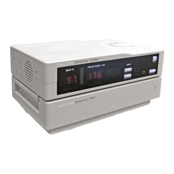
Nellcor Symphony
™
N-3000 Patient Monitor
SpO
and ECG Capabilities
2
To contact Nellcor Puritan Bennett's representative: In the United States, call 1-800-NELLCOR or 510 463-4000;
outside the United States, call your local Nellcor Puritan Bennett representative.
012 3
Caution: Federal law (U.S.) restricts this device to sale by or on the order of a physician.
© 1996 Nellcor Puritan Bennett Incorporated. All rights reserved.
034127A-0396
Advertisement
Table of Contents

Related Manuals for NELLCOR PURITAN BENNETT Symphony N-3000


Summary of Contents for NELLCOR PURITAN BENNETT Symphony N-3000
- Page 1 ™ N-3000 Patient Monitor and ECG Capabilities To contact Nellcor Puritan Bennett’s representative: In the United States, call 1-800-NELLCOR or 510 463-4000; outside the United States, call your local Nellcor Puritan Bennett representative. 012 3 Caution: Federal law (U.S.) restricts this device to sale by or on the order of a physician.
- Page 2 To obtain information about a warranty, if any, for this product, contact Nellcor Puritan Bennett Technical Services or your local Nellcor Puritan Bennett representative. Nellcor Puritan Bennett, Durasensor , Nellcor Symphony , Oxisensor II, and the Nellcor Puritan Bennett knob configuration are trademarks of Nellcor Puritan Bennett Incorporated.
-
Page 3: Table Of Contents
TABLE OF CONTENTS List of Figures List of Tables Section 1: Introduction ................Manual Overview................. Warnings, Cautions, and Notes........... 1.2.1 Warning ............... 1.2.2 Caution ................ 1.2.3 Note ................N-3000 Patient Monitor Description ..........Related Documents ..............Section 2: Routine Maintenance ............... Cleaning .................. - Page 4 Table of Contents Section 4: Configuration Mode, Service Mode, and Alarm Active Function ..................Introduction.................. Configuration Mode ..............4.2.1 Adult/Neonatal Mode Default ........4.2.2 Default SpO Upper Alarm Limit........4.2.3 Default SpO Lower Alarm Limit........4.2.4 Default Heart/Pulse Rate Upper Alarm Limit ....4.2.5 Default Heart/Pulse Rate Lower Alarm Limit ....
- Page 5 Table of Contents 4.3.26 Menu Item 38: SpO A/D-Cal Line Test ...... 4-23 4.3.27 Menu Item 39: SpO Enable Automatic Operation ..4-24 4.3.28 Menu Item 40: Set ECG Lead ........4-24 4.3.29 Menu Item 41: Set ECG Pacer Filter ......4-24 4.3.30 Menu Item 42: Set ECG Low Frequency Filter ....
- Page 6 Table of Contents Section 9: Specifications ................General..................Electrical ..................Physical Characteristics .............. Environmental ................Alarms ..................Factory Default Settings .............. Performance ................Appendix ..................... Error Types.................. User-Correctable Error Codes ............. Failure Error Codes ..............Internally Corrected Error Codes ..........Technical Supplement ................
- Page 7 Table of Contents N-3000 Expanded View ..............Repacking the N-3000 ..............S2-1 Oxyhemoglobin Dissociation Curve ..........S4-1 N-3000 Functional Block Diagram ........... S4-2 Timing Diagram ................S4-3 Internal/External Stackbus Connections.......... S-12 S4-4 Communications Sub module Block Diagram........S-19 S4-5 Display Board Block Diagram ............
-
Page 9: Section 1: Introduction
A note gives information that requires special attention. N-3000 PATIENT MONITOR DESCRIPTION The purpose and function of the Nellcor Symphony N-3000 patient monitor is to noninvasively and continuously monitor functional arterial oxygen saturation, ECG, pulse rate, and heart rate, for adult, pediatric, and neonatal patients in all hospital areas and hospital-type facilities. -
Page 10: Related Documents
Refer to the N-3000 operator’s manual. To understand the various Nellcor Puritan Bennett sensors and ECG leads that work with the monitor, refer to the individual sensor or leads directions for... -
Page 11: Section 2: Routine Maintenance
Inspect the exterior of the N-3000 for damage. Inspect safety labels for legibility. If the labels are not legible, contact Nellcor Puritan Bennett’s Technical Services Department or your local Nellcor Puritan Bennett representative. Verify that the unit performs properly as described in paragraph 3.3. -
Page 13: Section 3: Performance Verification
SECTION 3: PERFORMANCE VERIFICATION Introduction Equipment Needed Performance Tests Safety Tests Tests Piezo Speaker Test INTRODUCTION This section discusses the tests used to verify performance following troubleshooting and repairs. All tests are accomplished through the control panel. EQUIPMENT NEEDED Equipment Description AC power adapter SPS-N1 or SPS-I1... -
Page 14: Battery Operation Test
(This time may decrease if the N-3000 is operating in the stacked configuration with an N-3100 or N-3200.) Connect the Nellcor Puritan Bennett SRC-2 pulse oximeter tester to the monitor. Ensure that the monitor is not connected to AC power. -
Page 15: Power-Up Tests
All indicators light for a few seconds as illustrated in Figure 3-1. Verify that the SpO % (left-most display), HEART/PULSE RATE (middle), and AUXILIARY (right) displays all indicate “8.8.8.”. Symphony N-3000 Figure 3-1: Self-Test Display All displays turn off momentarily. Digital displays individually light in a scanning, or firefly, test pattern while the test is taking place. - Page 16 Section 3: Performance Verification 3.3.3.2 Adult Power-On Defaults and Alarm Limit Ranges Note: This paragraph and paragraph 3.3.3.3 are written using Nellcor Puritan Bennett factory-set defaults. If your institution has preconfigured custom defaults, those values will be displayed. Factory defaults can be reset using the service mode procedure described in paragraph 4.3.11, Menu Item 20, Reset to Factory Defaults, or the configuration mode procedure described in paragraph 4.2.8.6.
- Page 17 Section 3: Performance Verification From the normal mode steady state, press the LOWER ALARM LIMIT button two times rapidly. Rotate the control knob CCW. Verify that the HEART/PULSE RATE display reduces to a minimum of “30”. Press the AUDIBLE ALARM OFF button (located on top of the N-3000) and verify that the monitor emits a low-pitched beep when the button is pressed.
-
Page 18: Operation With A Pulse Oximeter Tester
3.3.4.5 Dynamic Operating Range Note: This section is written using Nellcor Puritan Bennett factory-set defaults. If your institution has preconfigured custom defaults, those values will be displayed. Factory defaults can be reset using the service mode procedure described in paragraph 4.3.11, Menu Item 20, Reset to Factory Defaults, or the configuration mode procedure described in paragraph 4.2.8.6. - Page 19 Section 3: Performance Verification Press and release the ON/STANDBY button to turn the monitor on. After the normal power-up sequence, verify that the SpO % and HEART/PULSE RATE displays initially indicate zeroes. Note: The pulse bar may occasionally indicate a step change as the monitor is in the pulse search mode.
-
Page 20: Pulse Tone Volume Control
Section 3: Performance Verification 3.3.4.3 Alarm Volume Control After completing the procedure in paragraph 3.3.4.2: Press and hold the AUDIBLE ALARM OFF button on the top of the monitor. Verify the following: “OFF” is displayed for approximately 3 seconds. After 3 seconds, a steady tone is heard at the default alarm volume setting, the HEART/PULSE RATE display indicates “VOL”, and the AUXILIARY display indicates the current default setting. - Page 21 Section 3: Performance Verification Move the RATE switch to 112 bpm. After approximately 30 seconds, verify that the HEART/PULSE RATE display has stopped flashing and that the display indications are within the tolerances shown below: Oxygen Saturation Range: 79 to 83% Pulse Rate Range: 110 to 114 bpm Note:...
-
Page 22: Operation With An Ecg Tester
3.3.5.1 Alarms With the monitor off, connect the ECG leads RA, LA, and LL to the appropriate jacks on the ECG tester. Nellcor Puritan Bennett ECG leads are color coded as follows: Right arm (RA) International - North American -... -
Page 23: Heartbeat Tone Volume Control
Section 3: Performance Verification Increase the heart rate setting on the ECG tester to 240 bpm. Verify that the heart rate “beep” increases its frequency and the HEART/PULSE RATE display value increases. Verify that the SpO % and AUXILIARY displays are blank. After at least five heartbeats, verify that the monitor displays a heart rate of 240 ±... - Page 24 Section 3: Performance Verification The monitor displays a heart rate of 60 ± 5 bpm. Select the following settings on the ECG tester: PARAMETER SETTING HEART RATE 240 bpm AMPLITUDE 2 millivolt LEAD SELECT SINUS RHYTHM Normal Verify the following monitor reaction: The heart rate “beep”...
-
Page 25: Normal Operation
3.3.6.1 LED Excitation Test This procedure uses normal system components to test circuit operation. A Nellcor Puritan Bennett Oxisensor II oxygen transducer, model D-25, is used to examine LED intensity control. The red LED is used to verify intensity modulation caused by the LED intensity control circuit. -
Page 26: Ecg Cable Off And Lead Off Tests
Connect ECG electrodes to the patient. Connect a Nellcor Puritan Bennett SCE-10 ECG cable to the N-3000. Connect Nellcor Puritan Bennett ECG leads to the cable. Connect the ECG leads to the electrodes on the patient according to the leads directions for use. - Page 27 Section 3: Performance Verification Connect a Nellcor Puritan Bennett Durasensor oxygen transducer, model DS-100A, to the sensor input cable. Clip the DS-100A to the subject as recommended in the sensor directions for use. Connect ECG electrodes to the patient. Connect a SCE-10 ECG cable to the N-3000. Connect ECG leads to the cable.
-
Page 28: Serial Port Voltages
Section 3: Performance Verification Perform the following procedure to test the serial port voltages. Connect the monitor to an AC power source through the SPS power supply and turn the monitor on. (The serial port is functional only when the N-3000 is operated from an AC power source.) Connect a 6-pin miniature connector adapter to the serial interface port. -
Page 29: Ecg Cable Test
Section 3: Performance Verification 3.3.6.5 ECG Cable Test The following test should be completed after defibrillation has been performed on a patient attached to ECG leads and a Nellcor Puritan Bennett SCE-10 ECG cable. Perform the following procedure to test the ECG cable. -
Page 30: Electrical Leakage
Section 3: Performance Verification 3.4.1 Ground Integrity This test verifies the integrity of the power cord ground wire from the AC plug and connection with the SPS external power supply chassis ground. Configure the electrical safety analyzer as follows: Function: Ground resistance test Range: mΩ... - Page 31 Section 3: Performance Verification 3.4.2.2 Patient Source Current This test is in compliance with AAMI Standard ES1, paragraph 3.3.2. Patient Source Current is measured between any individual patient connection and power (earth) ground. Configure the electrical safety analyzer as follows: Function: Leakage µA...
-
Page 32: Spo 2 Tests
Section 3: Performance Verification TESTS The following tests can be used to verify, analyze, and troubleshoot the SpO circuitry of the N-3000: • RCAL Circuit Test • LED Drive Tests The tests require use of the SRC-2 tester and the service mode, as detailed in paragraph 4.3. -
Page 33: Piezo Speaker Test
Section 3: Performance Verification The SpO IR LED drive value “170” is displayed in the HEART/PULSE RATE display. The IR indicator on the SRC-2 is illuminated. Rotate the knob to adjust the IR LED drive level indicated in the HEART/PULSE RATE display to 255. While watching the IR indicator on the SRC-2, confirm the setting by pressing the UPPER ALARM LIMIT button. - Page 34 Section 3: Performance Verification Caution: Observe ESD (electrostatic discharge) precautions when working within the unit. Ensure that the N-3000 is turned off. Disconnect the monitor from the SPS power supply. Set the N-3000 upside down facing you, as shown in Figure 3-6. Battery cover Squeeze Battery cover...
- Page 35 Section 3: Performance Verification Battery cover Battery Power connector Battery bracket Figure 3-7: Speaker Test Turn the monitor on by pressing the ON/STANDBY button. When the power-on self-test is complete, disconnect the power connector from the battery. Verify that a shrill, beeping alarm is emitted from the speaker.
-
Page 37: Section 4: Configuration Mode, Service Mode, And Alarm Active Function
SECTION 4: CONFIGURATION MODE, SERVICE MODE, AND ALARM ACTIVE FUNCTION Introduction Configuration Mode Service Mode Alarm Active Function INTRODUCTION This section discusses use of the configuration mode to reconfigure power-on default values, the service mode to identify and correct monitor difficulties, and the alarm active function. -
Page 38: Adult/Neonatal Mode Default
Section 4: Configuration Mode, Service Mode, and Alarm Active Function Table 4-1 lists the default settings that can be configured and the respective entry procedures to access the settings. Methods used to change the default settings are detailed in paragraphs 4.2.1 through 4.2.8. Table 4-1: Configuration Mode Menu Power on Default Button Press Procedure from... -
Page 39: Default Spo Lower Alarm Limit
Section 4: Configuration Mode, Service Mode, and Alarm Active Function To change the upper alarm limit value, rotate the knob on top of the monitor (or, if stacked with an N-3200 in the configuration mode, the knob on the N-3200). You cannot decrease the value lower than the current SpO lower alarm limit default setting. -
Page 40: Default Alarm Volume
Section 4: Configuration Mode, Service Mode, and Alarm Active Function 4.2.6 Default Alarm Volume Perform the following steps to adjust the default alarm volume: From the configuration mode steady state, press and hold the AUDIBLE ALARM OFF button. After 3 seconds, a continuous tone at the current volume setting is emitted. -
Page 41: Pulse Tone Volume
Section 4: Configuration Mode, Service Mode, and Alarm Active Function Table 4-2: Configuration Menu Menu Paragraph Number Configurable Setting Described Timeout Pulse tone volume 4.2.8.1 3 seconds UIF software version report 4.2.8.2 10 seconds software version report 4.2.8.3 10 seconds Serial port baud rate 4.2.8.4 3 seconds... - Page 42 Section 4: Configuration Mode, Service Mode, and Alarm Active Function 4.2.8.2 UIF Software Version Report From the configuration menu steady state, rotate the knob until “1” is displayed in the SpO % display. Press the UPPER ALARM LIMIT button. The UIF software version number is the left-most digit in the SpO display.
- Page 43 Section 4: Configuration Mode, Service Mode, and Alarm Active Function Selecting “10” causes patient trend data to be recorded every 10 seconds. Each patient parameter value will be the average of all data samples for each parameter during the sample period. Data is stored for the most recent 24 hours of patient monitoring.
- Page 44 Section 4: Configuration Mode, Service Mode, and Alarm Active Function 4.2.8.8 Pulse Tone Source Menu item number “7” allows you to select the default heart/pulse tone source. Selecting “SPO” causes the pulse rate measured by an SpO sensor to provide the pulse tone. Selecting “ECG” causes the heart rate measured by ECG leads to provide the pulse tone.
-
Page 45: Service Mode
Section 4: Configuration Mode, Service Mode, and Alarm Active Function 4.2.8.11 ECG Low Frequency Filter Status Menu item number “10” allows you to select “ON” or “OFF” as the low frequency filter default. Selecting “ON” enables a .05 Hz, ECG channel, high -pass filter, providing better ST segment resolution. - Page 46 Section 4: Configuration Mode, Service Mode, and Alarm Active Function Note: Failure errors (refer to Troubleshooting section for an explanation of failure errors and error codes) may be encountered by the N-3000 upon entering the service mode. The N-3000 will automatically access the menu item used to correct this situation.
-
Page 47: Service Mode Steady State - Main Menu
Section 4: Configuration Mode, Service Mode, and Alarm Active Function Table 4-3: Service Mode Steady State - Main Menu Menu Paragraph Type of Report/Test Described Software Version Report 4.3.1 Knob and Lamp Test 4.3.2 Button Test 4.3.3 Speaker Test 4.3.4 Internal Configuration Code (ICC) Report 4.3.5 Total Operating Hours Report... -
Page 48: Menu Item 1: Software Version Report
This report identifies the software versions of the UIF and SpO modules. From the service mode steady state, select menu item 1 by rotating the Nellcor Puritan Bennett knob until “1” appears in the SpO % display. Press the UPPER ALARM LIMIT button. A “1.0” appears in the SpO display. -
Page 49: Menu Item 2: Knob And Lamp Test
Section 4: Configuration Mode, Service Mode, and Alarm Active Function 4.3.2 Menu Item 2: Knob and Lamp Test This test verifies that indicators, front-panel lamps, and the control knob are functional. From the service mode steady state, select menu item 2 by rotating the knob until “2”... -
Page 50: Menu Item 4: Speaker Test
Section 4: Configuration Mode, Service Mode, and Alarm Active Function Rotate the knob CW or CCW to return to the service mode steady state. 4.3.4 Menu Item 4: Speaker Test This test verifies that the volume control is functional and determines whether or not there are any discontinuities or saturation conditions in the audible output. -
Page 51: Menu Item 6: Total Operating Hours Report
Section 4: Configuration Mode, Service Mode, and Alarm Active Function 4.3.6 Menu Item 6: Total Operating Hours Report This report displays the total number of operating hours logged by the unit since it was produced. From the service mode steady state, select menu item 6 by rotating the knob until “6”... -
Page 52: Menu Item 18: Power Status
Section 4: Configuration Mode, Service Mode, and Alarm Active Function Verify that this number agrees with the number on the monitor external label. If the number does not agree, the number on the external label should be changed to agree with the displayed number. Press the LOWER ALARM LIMIT button to return to the service mode steady state. -
Page 53: Menu Item 20: Reset To Factory Defaults
Section 4: Configuration Mode, Service Mode, and Alarm Active Function 4.3.11 Menu Item 20: Reset to Factory Defaults This function allows you to reset the monitor to the factory default settings (see the Specifications section of this manual). From the service mode steady state, select menu item 20. As soon as you press the UPPER ALARM LIMIT button, the default settings are reset. -
Page 54: Menu Item 23: Enable/Disable Alarm Silence Reminder
Section 4: Configuration Mode, Service Mode, and Alarm Active Function Press the UPPER ALARM LIMIT button to store the default setting. Press the LOWER ALARM LIMIT button to return to the service mode steady state. 4.3.14 Menu Item 23: Enable/Disable Alarm Silence Reminder This function allows you to disable or enable the alarm silence reminder feature. -
Page 55: Menu Item 28: Enable/Disable Battery Charge Circuit
Section 4: Configuration Mode, Service Mode, and Alarm Active Function Press the LOWER ALARM LIMIT button to return to the service mode steady state. 4.3.16 Menu Item 28: Enable/Disable Battery Charge Circuit This test allows you to turn the battery charging circuit on or off. From the service mode steady state, select menu item 28 by rotating the knob until “28”... -
Page 56: Menu Item 31: Spo Ir And Red Offset Report
Section 4: Configuration Mode, Service Mode, and Alarm Active Function Press the LOWER ALARM LIMIT button to return to the service mode steady state. 4.3.19 Menu Item 31: SpO IR and Red Offset Report This function allows you to validate the operation of the SpO module. -
Page 57: Menu Item 33: Spo Ir Led Drive Test
Section 4: Configuration Mode, Service Mode, and Alarm Active Function 4.3.21 Menu Item 33: SpO IR LED Drive Test This function allows you to validate sensors and/or the operation of the SpO module. Connect the sensor to the N-3000. Verify that the SpO module is set for automatic operation using menu item 39 (paragraph 4.3.27). -
Page 58: Menu Item 35: Spo Dm-Gain Test
Section 4: Configuration Mode, Service Mode, and Alarm Active Function Press the LOWER ALARM LIMIT button to return to the service mode steady state. 4.3.23 Menu Item 35: SpO DM-Gain Test This function allows you to validate sensors and/or the operation of the SpO module. -
Page 59: Menu Item 37: Set Spo Analog Test Mode
Section 4: Configuration Mode, Service Mode, and Alarm Active Function Press and hold the PRINT button to display the SpO corrected IR and red output signals as described in menu item 32. Release the PRINT button. Press the LOWER ALARM LIMIT button to return to the service mode steady state. - Page 60 Section 4: Configuration Mode, Service Mode, and Alarm Active Function Press the LOWER ALARM LIMIT button to return to the service mode steady state. 4.3.27 Menu Item 39: SpO Enable Automatic Operation This function allows you to enable or disable the SpO module automatic operation mode.
- Page 61 Section 4: Configuration Mode, Service Mode, and Alarm Active Function From the service mode steady state, select menu item 40 by rotating the knob until “40” appears in the SpO % display. Press the UPPER ALARM LIMIT button. “ON” or “OFF” is displayed in the HEART/PULSE RATE display. To change the current setting, rotate the knob until the desired setting is displayed.
- Page 62 Section 4: Configuration Mode, Service Mode, and Alarm Active Function 4.3.32 Menu Item 44: ECG POST Test Signal This function allows you to send an internal test signal either singly or repetitively from the ECG module for service mode testing. From the service mode steady state, select menu item 44 by rotating the knob until “44”...
- Page 63 Section 4: Configuration Mode, Service Mode, and Alarm Active Function Press the LOWER ALARM LIMIT button to select the setting and return to the service mode steady state. 4.3.35 Menu Item 47: Display ECG Output Value This function allows you to test the ECG A/D channel. From the service mode steady state, select menu item 47 by rotating the knob until “47”...
- Page 64 Section 4: Configuration Mode, Service Mode, and Alarm Active Function Press the LOWER ALARM LIMIT button to return to the service mode steady state. 4.3.37 Menu Item 60: Set Serial Port Baud Rate This function allows you to set the default serial port baud rate. From the service mode steady state, select menu item 60 by rotating the knob until “60”...
- Page 65 Section 4: Configuration Mode, Service Mode, and Alarm Active Function 4.3.39 Menu Item 62: Serial Port Transmit Test This test verifies that, when the N-3000 is connected to a PC through the N-3000 serial port, the serial port transmit hardware is functional. Note: The N-3000 must be operating from AC power to perform this menu item.
- Page 67 Nellcor Puritan Bennett Technical Services provides technical assistance information and replacement parts. To obtain replacement parts, contact Nellcor Puritan Bennett or your local Nellcor Puritan Bennett representative. Refer to parts by the part names and part numbers listed in Section 7, Spare Parts.
-
Page 68: Problem Categories
Taking the recommended actions discussed in this section will correct the majority of problems you will encounter. However, problems not covered here can be resolved by calling Nellcor Puritan Bennett Technical Services or your local representative. Table 5-1: Problem Categories... -
Page 69: Power Problems
Section 5: Troubleshooting 5.6.1 Power Power problems are related to AC and/or DC. Table 5-2 lists recommended actions to power problems. Table 5-2: Power Problems Condition Recommended Action 1. BATTERY-IN- 1. Ensure that the SPS power supply is plugged into USE/BATTERY an operational AC outlet. - Page 70 If the action requires replacement of a PCB, refer to Section 6, Disassembly Guide . If the recommended action fails to solve the problem, notify Nellcor Puritan Bennett Technical Services or your local representative. Refer to the Appendix for a further explanation of the codes.
-
Page 71: N-3000 Failure Error Codes
Section 5: Troubleshooting Table 5-3: N-3000 Failure Error Codes Error Code Recommended Action 1. Turn the monitor off, then on again. 2. If the error code still appears, power-down the monitor and verify that the UIF PCB ROM (U3) is securely seated in its socket. -
Page 72: N-3000 Failure Error Codes
2. Use the service mode, menu item 29, to verify the compatibility of your software. 3. If the error code still appears, verify compatibility of the ROMs by calling Nellcor Puritan Bennett Technical Services or your local representative. 203, 206, 1. -
Page 73: Buttons/Knob Problems
5.6.3 Buttons/Knob Table 5-4 lists symptoms of problems relating to nonresponsive buttons or the Nellcor Puritan Bennett knob and recommended actions. If the action requires replacement of a PCB, refer to Section 6, Disassembly Guide . Table 5-4: Buttons/Knob Problems... -
Page 74: Display/Alarms Problems
Section 5: Troubleshooting 5.6.4 Display/Alarms Table 5-5 lists symptoms of problems relating to nonfunctioning displays, audible tones or alarms, and recommended actions. If the action requires replacement of a PCB or module, refer to Section 6, Disassembly Guide. Table 5-5: Display/Alarms Problems Condition Recommended Action 1. -
Page 75: Operational Performance Problems
Section 5: Troubleshooting 5.6.5 Operational Performance Table 5-6 lists symptoms of problems relating to operational performance (no error codes displayed) and recommended actions. If the action requires replacement of a PCB or module, refer to Section 6, Disassembly Guide. Table 5-6: Operational Performance Problems Condition Recommended Action 1. -
Page 76: Stack Problems
Section 5: Troubleshooting 5.6.6 Stacked Operation Table 5-7 lists symptoms of problems encountered while in the stacked configuration with the N-3100 and recommended actions. Refer to the N-3100 service manual for more troubleshooting information. For problems encountered while stacked with the N-3200, refer to the N-3200 service manual. - Page 77 Section 5: Troubleshooting Table 5-7: Stack Problems - (Continued) Condition Recommended Action 5. The N-3000 and N-3100 1. The N -3000 battery may be discharged. To do not operate when recharge the battery, keep the N-3000 disconnected from the connected to its external power supply. external power supply.
-
Page 78: Serial Port Problems
Section 5: Troubleshooting 5.6.7 Serial Port Table 5-8 lists symptoms of problems relating to the serial port and recommended actions. If the action requires replacement of a PCB or module, refer to Section 6, Disassembly Guide. Table 5-8: Serial Port Problems Condition Recommended Action 1. - Page 79 SECTION 6: DISASSEMBLY GUIDE Introduction Removing the Battery Battery Replacement Fuse Replacement Monitor Disassembly Removing the Alarm Speaker Removing the SpO PCB and SpO Controller PCB Removing the Communications PCB Removing the ECG PCB and ECG Controller PCB 6.10 Removing the UIF PCB and Display PCB 6.11 Control Knob Assembly Replacement 6.12 Lithium Battery Replacement 6.13 Reassembly...
- Page 80 Section 6: Disassembly Guide REMOVING THE BATTERY Caution: If it is necessary to apply AC power while the battery cover is removed, do not connect the SPS power supply to the monitor while the power supply is plugged into AC power. Instead, first connect the power supply to the monitor, then connect the power supply to AC power.
- Page 81 Section 6: Disassembly Guide Lift the battery out of the battery bracket, as shown in Figure 6-2. It may be necessary to use the edge of a flat tip screwdriver to gently pry the battery loose. Battery cover Battery Power connector Battery bracket Figure 6-2: Removing the Battery...
- Page 82 Section 6: Disassembly Guide FUSE REPLACEMENT Complete the procedure in paragraph 6.2. Replace the fuses as shown in Figure 6-3 with an equivalent replacement. Fuse F2, 2.5 amp Fuse F1, 1 amp 250V, Slo Blow 250V, Slo Blow Battery Figure 6-3: N-3000 Fuses Reinstall the battery and battery cover.
- Page 83 Section 6: Disassembly Guide Pull the carrying handle down to the right. Pull the unit apart, swinging the bottom half to your left, as illustrated in Figure 6-5. SpO2 Connector J13 Docking connector cable Communications Bottom enclosure Figure 6-5: Opening the N-3000 Monitor Caution: The battery fuse (F2) on the Docking Connector PCB must be removed as indicated in paragraph 6.4 before disconnecting the docking connector cable from connector J13.
- Page 84 Section 6: Disassembly Guide If a continuous 3.3 volt signal at pin 6 of the serial port (Figure 3.3) is required (as when using the SOC-3 adapter), change the SW3 settings as follows: SW3 - Position 1 = OFF; Position 2, 3, and 4 = ON If RS-422 settings are required, change SW1 and SW2 as follows: SW1 - Positions 1, 3, 5, and 7 = OFF;...
- Page 85 Section 6: Disassembly Guide Remove the rear panel, rear-panel insulator, and NEW PATIENT/NEONATAL button by lifting up and rotating out of the chassis channel guides as illustrated in Figure 6-7. Rear panel Rear panel insulator Sp02 PCB Sp02 controller PCB Pemm stud ECG PCB Figure 6-7: Rear Panel and SpO...
- Page 86 Section 6: Disassembly Guide Using a 1/4 inch socket or needle-nose pliers, remove the Communications PCB by removing the four 1/4-inch nuts that secure it to the UIF PCB (Figure 6-8). After removing the nuts, lift straight up. Communications PCB 1/4-inch nut Jumper J6 Top enclosure...
- Page 87 Section 6: Disassembly Guide J5 connector UIF PCB Piezo power loss alarm speaker Lithium backup battery Speaker boost lithium battery Control knob ribbon cable J3 connector Display PCB Front panel bezel Figure 6-9: Display PCB and UIF PCB Disassembly Using a Phillips-head screwdriver, remove the six screws securing the UIF PCB to the chassis.
- Page 88 Section 6: Disassembly Guide Replace the Instrument Identification label by attaching it to the enclosure on the bottom of the unit. Confirm the IID number using the service mode menu item 17. 6.11 CONTROL KNOB ASSEMBLY REPLACEMENT Complete the procedure in paragraph 6.10. The top cover appears as illustrated in Figure 6-10.
- Page 89 Slide battery (or batteries) from underneath the spring clips. Do not dispose of lithium batteries by placing them in the regular trash. Dispose of properly or return to Nellcor Puritan Bennett Technical Services for disposal. Replace batteries, observing correct polarity (positive terminal up).
- Page 91 Section 7: Spare Parts SECTION 7: SPARE PARTS Introduction INTRODUCTION Spare parts, along with part numbers, are shown below. Item numbers in parentheses correspond to the callout numbers in Figure 7-1. Item Description Part No. Cover, battery 031763 Battery, lead-acid, 12V-2Ah 640115 Bracket, battery 030487...
- Page 92 Section 7: Spare Parts Item No. Description Part No. not pictured SPS-I1 power supply, International 033876 not pictured SPS-N1 power supply, North American 033877 not pictured NPC-I power cord, International 901862 not pictured NPC-NA power cord, North American 071505 not pictured OXISENSOR II assortment pack ASP3 not pictured...
-
Page 93: N-3000 Expanded View
Section 7: Spare Parts Figure 7-1 shows the N-3000 expanded view with numbered callouts relating to the spare parts list. Rear panel (28) Battery cover (1) New patient/neonatal button (38) Lead acid battery (2) Battery bracket (3) Bottom cover (4) Carrying handle (5) Docking connector PCB (40) Left panel (6) -
Page 95: Repacking The N-3000
GENERAL INSTRUCTIONS Pack the monitor carefully. Failure to follow the instructions in this section may result in loss or damage not covered by the Nellcor Puritan Bennett warranty. If the original shipping carton is not available, use another suitable carton; North American customers may call Nellcor Puritan Bennett Technical Services to obtain a shipping carton. - Page 96 Section 8: Packing for Shipment Label carton with shipping address, return address and RGA number, if applicable. REPACKING IN A DIFFERENT CARTON If the original carton is not available: Place the monitor in a plastic bag. Locate a corrugated cardboard shipping carton with at least 200 pounds per square inch (psi) bursting strength.
- Page 97 SECTION 9: SPECIFICATIONS General Electrical Physical Characteristics Environmental Alarms Factory Default Settings Performance GENERAL Designed to meet safety requirements of: UL 544, UL 2601-1 CSA-C22.2 No. 601-1-M90, IEC 601-1 (type CF), ISO 9919, RFE per VFG 243, EMC per IEC 801 series. ELECTRICAL Protection Class Class I: per I.E.C.
- Page 98 Section 9: Specifications PHYSICAL CHARACTERISTICS 6.8 cm x 23.9 cm x 14.7 cm Dimensions (2.65 in. x 9.41 in. x 5.79 in.) Note: When operating without the docking pedestal (docked), the height is 5.4 cm (2.13 in.) instead of 6.8 cm (2.65 in.) Weight 1.8 kg (3.96 lb.) ENVIRONMENTAL...
- Page 99 Section 9: Specifications PERFORMANCE Range 0–100% Pulse/Heart Rate: 20–250 bpm Alarm Characteristics Alarm Pitch Pulse Width Pulse Repitition Priority (+ 30 Hz) (+ 20 msec) Interval ( + 20 msec) High 932 Hz 255 msec 320 msec Medium 752 Hz 400 msec 700 msec 500 Hz...
- Page 100 Section 9: Specifications ECG-Specific Performance Characteristics Characteristic Value Resolution 1 bpm CMRR (Common Mode Rejection >90 dB at 50 or 60 Hz Ratio) Frequency Response bandwidth of 0.5 to 40 Hz +1 to -1.5 dB at 0.5 Hz +1 to -3 dB at 40 Hz Input Impedance 2.5 megohms at 10 Hz Defibrillator Discharge Recovery...
- Page 101 Section 9: Specifications Pacemaker Pulse Rejection Capability The following pacemaker pulses without over/undershoot will be rejected by the N-3000: Pacemaker Pulse Pacemaker Amplitude Pulse Width + 2 mV 0.1 and 2.0 msec + 700 mV 0.1 and 2.0 msec The following pacemaker pulses with over/undershoot will be rejected by the N-3000.
-
Page 103: Error Types
APPENDIX Error Types User Correctable Error Codes Failure Error Codes Internally Corrected Error Codes ERROR TYPES There are six classes of errors that may occur during the operation of the N-3000, as indicated in Table A-1. Table A-1: Error Types Error Type Description 1. -
Page 104: N-3000 User-Correctable Error Codes
Appendix In all cases, an attempt to store an error in the Error Log may fail due to failure or corruption of the Error Log in EEPROM. This condition alone does not constitute a failure error and operation of the instrument proceeds as if the error has been successfully logged. -
Page 105: N-3000 Internally Corrected Error Codes
Table A-4 lists the internally corrected error codes in numerical order. It is not normally necessary for service personnel to access the Error Log. However, if you find it necessary to contact Nellcor Puritan Bennett Technical Services or your local Nellcor Puritan Bennett representative, they may request information from the Error Log. - Page 106 Appendix Table A-4: N-3000 Internally Corrected Error Codes - (Continued) Error Code Explanation UIF stack overflow. UIF general watchdog reset. UIF memory corruption. UIF unexpected interrupt. UIF RTXC executive function failed. UIF stack communication bus common code failed. UIF state machine illegal transition or unknown state. External Port Service internal error (RS232 handler).
- Page 107 TECHNICAL SUPPLEMENT S1 Introduction S2 Oximetry Overview S3 Stackbus Interconnect S4 Circuit Analysis S5 Schematic Diagrams INTRODUCTION This Technical Supplement provides the reader with a discussion of oximetry principles and a more in-depth discussion of N-3000 circuits. A functional overview and detailed circuit analysis are supported by block and schematic diagrams.
- Page 108 Technical Supplement S2.2 Functional Versus Fractional Saturation This monitor measures functional saturation — oxygenated hemoglobin expressed as a percentage of the hemoglobin that can transport oxygen. It does not detect significant amounts of dysfunctional hemoglobin, such as carboxyhemoglobin or methemoglobin. In contrast, hemoximeters such as the IL482 report fractional saturation —...
- Page 109 Technical Supplement RS-485 drivers and receivers are used for signaling. A proximity sensor in the bottom of the N-3000 or N-3100 detects when the monitor is docked, enabling the stackbus signals. Access to the stackbus is accomplished through token passing. A token designates which station (module or instrument) has control of the stackbus.
- Page 110 Technical Supplement Module Module External Power Supply Communi- Docking cations Connector Module Module Battery Display Module – Visual Annunciators and Controls Figure S4-1: N-3000 Functional Block Diagram S4.2 Circuit Description The following paragraphs discuss the operation of each of the printed circuit boards within the N-3000 oximeter.
- Page 111 Technical Supplement The transformer flyback pulse is rectified by CR7 and filtered by C12, C57, and R5 to create VCCI. The other two transformer windings have three times as many turns than the VCCI winding. These windings are rectified by CR5 and CR6 to achieve ±15 volts during the flyback cycle.
- Page 112 Technical Supplement Components R30 and C24 filter any high-frequency noise on VCCI that is beyond the bandwidth of U32. Finally, Q13, R104, and R105 turn the LEDs off between pulses. Differential Input Amplifier Input op amp U23 converts the differential current to a voltage. One side of the output is coupled through capacitor C48 while the other output is used as a reference that is switched by U24 onto R78 only during one channel on/off cycle.
- Page 113 Technical Supplement S4.2.2 ECG Module The following paragraphs describe the functional areas of the ECG PCB. There are circuits on the board that are also shown on the schematic diagrams related to respiration monitoring. These circuits are not used in this model N-3000 and are not described.
- Page 114 Technical Supplement output of which is the RAW_ECG signal which is applied to the ECG lead I/II/III display and the pacemaker detection and suppression circuits. ECG Lead I/II/III Display Circuit The RAW_ECG signal from the servo amp circuit is connected to an amplifier in U19.
-
Page 115: Battery Charge
Technical Supplement Power switching and battery charging are controlled by U20, a BQ2001 power monitor IC. The BQ2001 power monitor IC has three sources of power input: CHARGEBUS from the SPS-N or SPS-I power supply, the N-3000 lead-acid battery, or lithium battery BT1. The ON/STANDBY button is connected to BQ2001, which controls the gate of power transistor Q10. - Page 116 Technical Supplement The battery charging circuitry is a constant voltage charger. When the battery is discharged, its output voltage is low (about 10V) and the maximum charge rate (approximately 350mA) is applied to it. As the battery charges, its output voltage rises, reducing the amount of current delivered to it by CHARGEBUS.
- Page 117 Technical Supplement Display Controllers — These controllers are used by the processor to display data on the display board. Processor Code PROM (U10) — The PROM contains the program that the processor uses to perform the user interface and gateway functions for the N-3000.
- Page 118 Technical Supplement The resultant amplitude controlled square wave is then sent to audio amplifier U4 to drive the 8-ohm speaker. The chip select for U5 is processor pin /CS5. Analog to Digital Converter — ADC U27 is an 8-bit analog to digital converter used by the processor to measure three different analog voltages.
- Page 119 Technical Supplement Watchdog Timer — Timer U21 ensures that processor U3 does not operate and switches the backup battery power from U20 to the RAMPWR supply when the +5 volt supply is below its lower regulation limit. This chip holds U3 in reset until the power supply is above its lower regulation limit.
- Page 120 Technical Supplement Table S4-2: J8 Connector - (Continued) Pin No. Pin Description Input/Output/Power NURSECALL Not Used Ground Power Interrupt from second COM20020 Analog power Power Ground Power Ground Power Reset DSL (data strobe low) SDCK (used for sub module detection) Chip select Read/Write Strobe J12, J22 —...
-
Page 121: J3 Knob Connector
Technical Supplement J5 — Connector J5 connects to the display board, which allows the UIF module to control the monitor display. Signals at this connector include power, serial clock and data lines, button signal, and charging battery indicator current. Table S4-4: J5 Display Connector Pin No. - Page 122 Technical Supplement CPU Reset Voltage monitor U2, shown in the upper left-hand corner of the schematic diagram, generates the reset for U1. Reset is held low until Vcc raises above 4.6 volts. After Vcc is above 4.6 volts, reset is tri-stated and pulled high by R10.
- Page 123 Technical Supplement Programmable Clock The clock frequency on the SpO controller board is programmed via software. The clock signal is labeled CTRL_CLK. The clock circuitry consists of U7 and U10. One half of U7 takes a 20 MHz input and produces three output frequencies: 10 MHz, 2.5 MHz, and 1.25 MHz.
- Page 124 Technical Supplement Resistor R22 pulls the U4 OE signal state to low during normal operation. If this signal state is high, the U4 output is disabled. RAM Memory RAM chips U5 and U8 provide the ECG Controller board with 256K bytes of memory.
- Page 125 Technical Supplement Connector J5 contains the signals for communicating with the UIF board (J8), as detailed in Table S4-2. Auxiliary connector J2 on the communications PCB is for future expansion. Serial Communications Serial communications are available only when the SPS power supply is connected to the N-3000 docking connector and plugged into an AC outlet.
- Page 126 Technical Supplement Selecting RS422 serial signaling is accomplished by moving switches S2,S4,S6,S8 on SW1 and SW2 to the on position and switches S1,S3,S5,S7 to the OFF position. This enables U10 and disables U9. With RS422 selected, J1 has the following pinout: TXD- RXD- Nurse Call/3.3V...
- Page 127 Technical Supplement The display driver ICs consist of U1, U2, and U3, which use a three-wire serial interface connect to the CPU (U3) on the UIF module. The three drivers used on this module are cascaded together and require that the host processor write 48 bits (16 x 3) to the board per each display update.