
Summary of Contents for Schweitzer Engineering Laboratories SEL-351A
- Page 1 SEL-351A, -1 Relay Distribution Protection System Instruction Manual 20080213 *PM351A-01-NB* Courtesy of NationalSwitchgear.com...
- Page 2 SEL products appearing in this document may be covered by US and Foreign patents. Schweitzer Engineering Laboratories, Inc. reserves all rights and benefits afforded under federal and international copyright and patent laws in its products, including without limitation software, firmware, and documentation.
-
Page 3: Table Of Contents
Directional Control for Neutral-Ground and Residual-Ground Overcurrent Elements (Not in SEL-351A-1) ....................4.9 Directional Control for Negative-Sequence and Phase Overcurrent Elements (Not in SEL-351A-1)..4.30 Directional Control Settings (Not in SEL-351A-1)..................4.38 Directional Control Provided by Torque Control Settings (Not in SEL-351A-1)......... 4.57 Section 5: Trip and Target Logic Trip Logic ................................ - Page 4 Rotating Default Display (Only on Models With LCD)................7.34 Section 8: Breaker Monitor and Metering Overview................................8.1 Breaker Monitor...............................8.2 Station DC Battery Monitor (Not in SEL-351A-1) ..................8.15 Demand Metering ............................8.20 Energy Metering ............................8.28 Maximum/Minimum Metering ........................8.29 Small Signal Cutoff for Metering ........................8.31 Synchrophasor Metering..........................8.32...
- Page 5 Data Map ..............................H.14 Point Remapping ............................H.20 DNP Settings Sheets SET: Appendix I: Using the SEL-251 and SEL-267 Relay Settings in the SEL-351A Relay Overview ................................I.1 Main Differences Between Settings for the SEL-251, SEL-267, and SEL-351A Relays........I.2 Other Differences Between the SEL-351A and the SEL-251-3 and SEL-267-5 Relays .........I.5...
- Page 6 Table of Contents Appendix J: SEL-351A Fast SER Protocol Overview................................J.1 Make Sequential Events Recorder (SER) Settings With Care................. J.2 Recommended Message Usage ........................J.3 Functions and Function Codes......................... J.4 Appendix K: QuickSet SEL-5030 Software ERATOR Overview.................................K.1 QuickSet System Requirements ....................K.2 ERATOR Installation ..............................K.3...
-
Page 7: List Of Tables
SEL-351A-1 Models ......................1.2 Table 1.3 Major Differences—SEL-351, SEL-351A, and SEL-351A-1 ..........1.3 Table 2.1 Communications Cables to Connect the SEL-351A to Other Devices ........ 2.19 Table 2.2 Output Contact Jumpers and Corresponding Output Contacts ..........2.36 Table 2.3 “Extra Alarm” Output Contacts and Corresponding Controlling Jumpers ......2.36 Table 2.4... - Page 8 Serial Communications Port Pin/Terminal Function Definitions .........10.4 Table 10.5 Serial Port Automatic Messages...................10.9 Table 10.6 Serial Port Command Summary ..................10.12 Table 10.7 SEL-351A Word and Its Correspondence to TAR Command ..........10.31 Table 10.8 SEL-351A Control Subcommands ..................10.37 Table 10.9 Valid Password Characters ....................10.38 Table 12.1 Event Types...........................12.5...
- Page 9 Permissible Message Periods Requested by Enable Message ..........L.7 Table L.5 SEL-351A Global Settings for Synchrophasors..............L.8 Table L.6 SEL-351A Serial Port Settings for Synchrophasors ..............L.8 Table L.7 Time Synchronization Relay Word Bits................L.11 Table L.8 SEL Fast Message Voltage and Current Selections Based on PHDATAV and PHDATAI...L.14...
- Page 10 This page intentionally left blank Courtesy of NationalSwitchgear.com...
-
Page 11: List Of Figures
SEL-351A Provides Underfrequency Load Shedding, Overcurrent Protection, and Reclosing for a Utility Distribution Feeder (Single Voltage Connection) ....2.33 Figure 2.26 Jumper, Connector, and Major Component Locations on the SEL-351A Main Board ..2.35 Figure 3.1 Levels 1 Through 4 Phase Instantaneous Overcurrent Elements ........... 3.2 Figure 3.2... - Page 12 (With Directional Control and Definite-Time Elements in SEL-351A) ......3.15 Figure 3.13 Levels 5 Through 6 Negative-Sequence Instantaneous Overcurrent Elements ....3.15 Figure 3.14 Phase Time-Overcurrent Element 51PT (With Directional Control Option in SEL-351A).3.17 Figure 3.15 A-Phase Time-Overcurrent Element 51AT (With Directional Control Option in SEL-351A) .............3.21 Figure 3.16...
- Page 13 Figure 6.7 Reclose Blocking for Islanded Generator ................6.24 Figure 6.8 Sequence Coordination Between the SEL-351A and a Line Recloser ........ 6.27 Figure 6.9 Operation of SEL-351A Shot Counter for Sequence Coordination With Line Recloser (Additional Settings Example 1) ............6.27 Figure 6.10...
- Page 14 Rotating Default Display Replaces Traditional Panel Light Installations ......7.35 Figure 8.1 Plotted Breaker Maintenance Points for a 25 kV Circuit Breaker..........8.3 Figure 8.2 SEL-351A Breaker Maintenance Curve for a 25 kV Circuit Breaker ........8.5 Figure 8.3 Operation of SEL Control Equation Breaker Monitor Initiation Setting......8.6 OGIC Figure 8.4...
- Page 15 Figure L.1 Phase Reference ........................L.3 Figure L.2 Waveform at Relay Terminals May Have Phase Shift ............L.4 Figure L.3 Correction of Measured Phase Angle..................L.4 Figure L.4 Sample MET PM Command Response................L.13 Instruction Manual SEL-351A Relay Date Code 20080213 Courtesy of NationalSwitchgear.com...
- Page 16 This page intentionally left blank Courtesy of NationalSwitchgear.com...
-
Page 17: Preface
The SEL-351A-1 model is a non-directional three-voltage version of the SEL-351A. Throughout the manual, notes indicate where features are not available in the SEL-351A-1. An overview of each manual section and topics follows: Preface. - Page 18 SHO Command (Show/View Settings) on page 10.25 for a list of the factory default settings the SEL-351A ships within a standard relay shipment. SEL-351A Command Summary. Briefly describes the serial port commands...
- Page 19 Examples This instruction manual uses several example illustrations and instructions to explain how to effectively operate the SEL-351A. These examples are for demonstration purposes only; the firmware identification information or settings values included in these examples may not necessarily match those in the current version of your SEL-351A.
- Page 20 Indicates a potentially hazardous situation that, if not avoided, could result in death or serious injury. DANGER Indicates an imminently hazardous situation that, if not avoided, will result in death or serious injury. SEL-351A Relay Instruction Manual Date Code 20080213 Courtesy of NationalSwitchgear.com...
- Page 21 Section 1 Introduction and Specifications Overview This section includes the following overviews of the SEL-351A Relay: ➤ SEL-351A Models on page 1.2 ➤ Applications on page 1.6 ➤ Hardware Connection Features on page 1.7 ➤ Communications Connections on page 1.9 ➤...
-
Page 22: Sel-351A Models
Table 1.2 are only the first part of an actual ordering number—enough to distinguish one model type from another. These numbers should not be used to order an SEL-351A. To order an SEL-351A, refer to the actual ordering information sheets. NOTE: IN current input options 0.2 A... -
Page 23: Table 1.3 Major Differences-Sel-351, Sel-351A, And Sel-351A-1
LCD. What’s the Difference The SEL-351A is based on the SEL-351 “family.” It has been created to offer a lower-cost product and includes some specific features that provide an easy... - Page 24 The bottom set of labels consists of a number only. These are consistent with the SEL-251 and SEL-267 relays. These two choices allow the SEL-351A to be wired into existing designs that use SEL-251 or SEL-267 terminal numbers. See Appendix I: Using the SEL-...
- Page 25 The VS channel is not Also in firmware revisions numbered R105 or higher, the auxiliary voltage supported in the SEL-351A-1. channel “VS” can be configured via global setting VSCONN = VS to accept a synchronism check or general-purpose voltage input or via VSCONN = 3V0 to accept a broken-delta residual voltage connection to be used in the zero- sequence voltage polarized ground directional elements.
-
Page 26: Applications
Recloser Line Recloser SEL-351R Installations The SEL-351R Recloser Control is a similar product to the SEL-351A. The SEL-351R is powered by 120 Vac and is ideally suited for applications outside the substation. q See Figure 2.14 Figure 2.15; w see Figure 2.16... -
Page 27: Hardware Connection Features
The relay rear-panel markings and the NOTE: The VS channel is not internal connections of terminals Z13 and Z14 are not changed. See Potential supported in the SEL-351A-1. Transformer Inputs for details on the broken-delta connection. Instruction Manual SEL-351A Relay Date Code 20080213 Courtesy of NationalSwitchgear.com... -
Page 28: Figure 1.2 Sel-351A Inputs, Outputs, And Communications Ports
Terminals 35 and 36 are not used on the SEL-251 Relay; w Terminals 41 and 42 are not used on either the SEL-251 or SEL-267 relays; not connected on SEL-351A-1 relay; e OUT107 can operate as an extra alarm. -
Page 29: Communications Connections
SEL-351 Relay (#2) OR . . . Front Panel #C234A Connect to the SEL-351 Port F Port F relays individually via the front-panel serial port Figure 1.3 SEL-351A Communications Connections Examples Instruction Manual SEL-351A Relay Date Code 20080213 Courtesy of NationalSwitchgear.com... -
Page 30: Specifications
0.20 A L/R = 40 ms Burden: 0.13 VA at 1 A, 1.31 VA at 3 A Cyclic Capacity (2.5 cycles/second): Additional Neutral Channel IN Options (Not in SEL-351A-1) 24 V 0.75 A L/R = 40 ms Nominal: 0.2 A 48 V 0.50 A... - Page 31 Four times per power system cycle. supply, optoisolated inputs, and Relay Element Setting Ranges and Accuracies output contacts. Impulse: IEC 60255-5:1977, 0.5 J, 5000 V Synchronism Check Elements (25) (Not in SEL-351A-1) Vibration: IEC 60255-21-1:1988 Slip Frequency [EN 60255-21-1:1995], Class 1 Pickup Range: 0.005–0.500 Hz, 0.001 Hz steps...
- Page 32 Pickup/Dropout 0.05 A IN Model: ±0.001 A, ±5% Accuracy: ±0.25 cycle, ±0.1% Transient Overreach: ±5% of pickup Substation Battery Voltage Monitor (Not in SEL-351A-1) Time Delay: 0.00–16,000.00 cycles, Pickup Ranges: 20–300 Vdc, 1 Vdc steps 0.25–cycle steps Measuring Accuracy: ±2%, ±2 Vdc Timer Accuracy: ±0.25 cycle, ±0.1%...
- Page 33 ±2.0° over the full temperature range Currents (1.25–7.50 A; 45–65 Hz) (5 A nominal) (0.25–2.50 A; 45–65 Hz) (1 A nominal) Magnitudes: ±2% Angles: ±1.0° at 25°C ±1.5° over the full temperature range Instruction Manual SEL-351A Relay Date Code 20080213 Courtesy of NationalSwitchgear.com...
- Page 34 This page intentionally left blank Courtesy of NationalSwitchgear.com...
-
Page 35: Section 2: Installation
Options include rack or panel mounting and terminal block or ® plug-in connector (Connectorized ) wiring. This section also includes information on configuring the relay for your application. Instruction Manual SEL-351A Relay Date Code 20080213 Courtesy of NationalSwitchgear.com... -
Page 36: Relay Mounting
Installation Relay Mounting Relay Mounting Rack Mount We offer the SEL-351A Relay in a rack-mount version that bolts easily into a standard 19-inch rack. See Figure 2.1. From the front of the relay, insert four rack screws (two on each side) through the holes on the relay mounting flanges. -
Page 37: Figure 2.1 Sel-351A Dimensions For Rack-Mount And Panel-Mount Models
Installation Relay Mounting Figure 2.1 SEL-351A Dimensions for Rack-Mount and Panel-Mount Models Instruction Manual SEL-351A Relay Date Code 20080213 Courtesy of NationalSwitchgear.com... -
Page 38: Front-Panel And Rear-Panel Connection Diagrams
All units can be ordered with either conventional terminal blocks or plug-in connectors. For model options, view the SEL-351A Model Option Tables on our website or contact your local SEL sales representative. Figure 2.3–Figure 2.5 show the various front-panel configurations available for the SEL-351A. -
Page 39: Figure 2.2 Sel-351A Rear-Panel Diagram-Conventional Terminal Blocks, Horizontal Example
Installation Front-Panel and Rear-Panel Connection Diagrams Model 0351A00H, or 0351A003, or 0351A005 Model 0351A10H, or 0351A103, or 0351A105 Figure 2.2 SEL-351A Rear-Panel Diagram—Conventional Terminal Blocks, Horizontal Example Instruction Manual SEL-351A Relay Date Code 20080213 Courtesy of NationalSwitchgear.com... -
Page 40: Figure 2.3 Sel-351A Front-Panel Drawings (Rack Mount Relays)
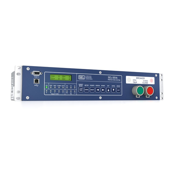
Installation Front-Panel and Rear-Panel Connection Diagrams Model 0351A0xH1, without LCD Model 0351AxxH2, with LCD Figure 2.3 SEL-351A Front-Panel Drawings (Rack Mount Relays) SEL-351A Relay Instruction Manual Date Code 20080213 Courtesy of NationalSwitchgear.com... -
Page 41: Figure 2.4 Sel-351A Front-Panel Drawings (Panel-Mount Relays)
Installation Front-Panel and Rear-Panel Connection Diagrams Models with LCD: 0351Axx32 & 0351Axx52 Models without LCD: 0351A0x31 & 0351A0x51 Figure 2.4 SEL-351A Front-Panel Drawings (Panel-Mount Relays) Instruction Manual SEL-351A Relay Date Code 20080213 Courtesy of NationalSwitchgear.com... -
Page 42: Figure 2.5 Sel-351A Front-Panel Drawing (Vertical Panel-Mount Relay, Model 0351A0X41) And Rear-Panel Drawing (Vertical Relay, Conventional Terminal Blocks, Model 0351A0041)
Installation Front-Panel and Rear-Panel Connection Diagrams Figure 2.5 SEL-351A Front-Panel Drawing (Vertical Panel-Mount Relay, Model 0351A0x41) and Rear-Panel Drawing (Vertical Relay, Conventional Terminal Blocks, Model 0351A0041) SEL-351A Relay Instruction Manual Date Code 20080213 Courtesy of NationalSwitchgear.com... -
Page 43: Figure 2.6 Sel-351A Rear-Panel Drawings-Connectorized Models 0351A0Wh, 0351A0W3, Or 0351A0W5 (Horizontal) And 0351A0W4 (Vertical)
Installation Front-Panel and Rear-Panel Connection Diagrams Vertical Model Top Figure 2.6 SEL-351A Rear-Panel Drawings—Connectorized Models 0351A0WH, 0351A0W3, or 0351A0W5 (Horizontal) and 0351A0W4 (Vertical) Instruction Manual SEL-351A Relay Date Code 20080213 Courtesy of NationalSwitchgear.com... -
Page 44: Making Rear-Panel Connections
(1) connector for POWER inputs (+ and – ➤ (1) spade connector for ground (GND) connection (chassis ground). These prewired connectors (and the serial port connector) are unique and may only be installed in one orientation. SEL-351A Relay Instruction Manual Date Code 20080213 Courtesy of NationalSwitchgear.com... -
Page 45: Figure 2.7 Sel-351A Plug-In Connector Coding (Top View; Model 0351A0W)
OUT105–ALARM Circuit Board-Mounted Connectors (male) IN101–IN103 IN104–IN106 Figure 2.7 SEL-351A Plug-In Connector Coding (Top View; Model 0351A0W) Models 0351Ax0 (Screw-Terminal Blocks) Tools: Phillips or slotted-tip screwdriver Parts: All screws are size #6-32. Locking screws can be requested from the factory. - Page 46 The standard output contacts are not polarity dependent. Optoisolated Inputs The optoisolated inputs in any of the SEL-351A models (e.g., IN102) are not polarity dependent. With nominal control voltage applied, each optoisolated input draws approximately 4 mA of current. Refer to Optoisolated Inputs on page 1.10...
- Page 47 Note the signal labels (VA, VB, VC, N, VS, NS) on terminals Z09–Z14. Figure 1.2 shows the internal connection for terminals VA, VB, VC, and N. Note also that VS/NS is a separate single-phase voltage input. Instruction Manual SEL-351A Relay Date Code 20080213 Courtesy of NationalSwitchgear.com...
- Page 48 3.49. Delta-Connected Voltages (Global setting PTCONN = DELTA) SEL-351A relays with firmware revision R105 (or higher) can be configured via Global setting PTCONN = DELTA to accept an open-delta PT connection. Phase-to-phase voltage up to 300 V continuous can be connected to the relay when it is connected as shown in Figure 2.23...
- Page 49 Elements (Not in SEL-351A-1) on page 3.36. SEL-351A relays with firmware revisions R104 and earlier do not have a VSCONN setting. In these relays, voltage input VS-NS operates in its traditional role of voltage input for synchronism check (as if setting VSCONN = VS).
-
Page 50: Figure 2.8 Broken-Delta Secondary Connection To Voltage Input Vs, Wye-Connected Pts
V , with respect to the wye- connected power system voltages connected to the voltage inputs VA-VB-VC-N (ABC rotation used in this example). For this scenario of the SEL-351A Relay Instruction Manual Date Code 20080213 Courtesy of NationalSwitchgear.com... -
Page 51: Figure 2.10 Broken-Delta Secondary Connection To Voltage Input Vs, Open-Delta Connected Pts
Open-Delta Setting PTCONN = DELTA Open Circuit SEL-351 Relay for Test Broken-Delta Step-Down Transformer Setting VSCONN = 3V0 Figure 2.10 Broken-Delta Secondary Connection to Voltage Input VS, Open-Delta Connected PTs Instruction Manual SEL-351A Relay Date Code 20080213 Courtesy of NationalSwitchgear.com... -
Page 52: Figure 2.9 Resultant Voltage V S
SEL-351A models. All ports are independent—you can communicate to any combination simultaneously. Serial PORT 1 on all the SEL-351A models is an EIA-485 port (4-wire). The serial PORT 1 plug-in connector accepts wire size AWG 24 to 12. Strip the wires 0.31 inches (8 mm) and install with a small slotted-tip screwdriver. -
Page 53: Table 2.1 Communications Cables To Connect The Sel-351A To Other Devices
C245A A corresponding main board jumper must be installed to power the Telenetics Modem with +5 Vdc (0.5 A limit) from the SEL-351A. See Figure 2.26 and Table 2.7. IRIG B Time-Code The SEL-351A accepts a demodulated IRIG-B time signal to synchronize the relay internal clock with some external source. -
Page 54: Sel-351A Ac/Dc Connection Diagrams For Various Applications
The voltage inputs do not need to be connected. Voltage is needed for voltage elements, synchronism check elements, frequency elements, voltage-polarized directional elements, fault location, metering (i.e., voltage, MW, MVAR), and frequency tracking. Voltage Channel VS (SEL-351A only) is shown connected for use in voltage and synchronism check elements and voltage metering. See Synchronism Check VS Connection (Global setting VSCONN = VS) on page 2.15... -
Page 55: Figure 2.13 Sel-351A Provides Overcurrent Protection For A Distribution Bus (Includes Fast Bus Trip Scheme) (Wye-Connected Pts)
The voltage inputs do not need to be connected. Voltage is needed for voltage elements, synchronism check elements, frequency elements, voltage-polarized directional elements, fault location, metering (i.e., voltage, MW, MVAR), and frequency tracking. Voltage Channel VS (SEL-351A only) is shown connected for use in voltage and synchronism check elements and voltage metering. See Synchronism Check VS Connection (Global setting VSCONN = VS) on page 2.15... -
Page 56: Figure 2.14 Sel-351A Provides Directional Overcurrent Protection And Reclosing For A Transmission Line (Wye-Connected Pts)
Scheme IN102 LINE Voltage Channel VS (in SEL-351A) does not need to be connected. Here, it is shown connected for use in voltage and synchronism check elements and voltage metering. See Synchronism Check VS Connection (Global setting VSCONN = VS) on page 2.15 Broken-Delta VS Connection (Global setting VSCONN = 3V0) on page 2.15. - Page 57 Scheme IN102 LINE Voltage Channel VS (in SEL-351A) does not need to be connected. Here, it is shown connected for use in voltage and synchronism check elements and voltage metering. See Synchronism Check VS Connection (Global setting VSCONN = VS) on page 2.15 Broken-Delta VS Connection (Global setting VSCONN = 3V0) on page 2.15.
-
Page 58: Figure 2.16 Sel-351A Provides Overcurrent Protection For A Delta-Wye Transformer Bank (Wye-Connected Pts)
(serial port communications, optoisolated input assertion, etc.), with desired supervision (e.g., hot bus check). For sensitive earth fault (SEF) applications, the SEL-351A should be ordered with channel IN rated at 0.2 A or 0.05 A nominal. See AC Current Input on page 1.10. -
Page 59: Figure 2.17 Sel-351A Provides Overcurrent Protection For A Transformer Bank With A Tertiary Winding (Wye-Connected Pts)
Although automatic reclosing is probably not needed in this example, output contact OUT102 can close the circuit breaker via initiation from various means (serial port communications, optoisolated input assertion, etc.), with desired supervision (e.g., hot bus check). Figure 2.17 SEL-351A Provides Overcurrent Protection for a Transformer Bank With a Tertiary Winding (Wye- Connected PTs) Instruction Manual... -
Page 60: Figure 2.18 Sel-351A Provides Overcurrent Protection For An Industrial Distribution Feeder (Core-Balance Current Transformer Connected To Channel In)
(serial port communications, optoisolated input assertion, etc.), with desired supervision. For sensitive earth fault (SEF) applications, the SEL-351A should be ordered with channel IN rated at 0.2 A or 0.05 A nominal. See AC Current Input on page 1.10. -
Page 61: Figure 2.19 Sel-351A Provides Dedicated Breaker Failure Protection
I = 3I ). But in this residual connection example, the neutral-ground and residual- ground overcurrent elements operate the same because I Figure 2.19 SEL-351A Provides Dedicated Breaker Failure Protection Instruction Manual SEL-351A Relay Date Code 20080213 Courtesy of NationalSwitchgear.com... -
Page 62: Figure 2.20 Sel-351A Provides Overcurrent Protection For A High-Impedance Or Low-Impedance Grounded System (Wye-Connected Pts)
Table 4.1–Table 4.3). Nondirectional sensitive earth fault (SEF) protection is also available. Note: The SEL-351A-1 is not equipped for this application. Figure 2.20 SEL-351A Provides Overcurrent Protection for a High-Impedance or Low-Impedance Grounded System (Wye-Connected PTs) SEL-351A Relay Instruction Manual Date Code 20080213 Courtesy of NationalSwitchgear.com... -
Page 63: Figure 2.21 Sel-351A Provides Overcurrent Protection For A Petersen Coil Grounded System (Wye-Connected Pts)
4.1– Table 4.3). Nondirectional sensitive earth fault (SEF) protection is also available. Note: The SEL-351A-1 is not equipped for this application. Figure 2.21 SEL-351A Provides Overcurrent Protection for a Petersen Coil Grounded System (Wye-Connected PTs) Instruction Manual SEL-351A Relay Date Code 20080213... -
Page 64: Figure 2.22 Sel-351A Provides Overcurrent Protection For An Ungrounded System (Wye-Connected Pts)
Table 4.1–Table 4.3). Nondirectional sensitive earth fault (SEF) protection is also available. Note: The SEL-351A-1 is not equipped for this application. Figure 2.22 SEL-351A Provides Overcurrent Protection for an Ungrounded System (Wye-Connected PTs) SEL-351A Relay Instruction Manual Date Code 20080213... -
Page 65: Figure 2.23 Sel-351A Provides Overcurrent Protection For An Ungrounded System (Open-Delta Connected Pts, Broken-Delta 3V0 Connection)
Check for VSCONN = 3V0 on page 2.16 for a suggested procedure. Note: The SEL-351A-1 is not equipped for this application. Figure 2.23 SEL-351A Provides Overcurrent Protection for an Ungrounded System (Open-Delta Connected PTs, Broken-Delta 3V0 Connection) Instruction Manual SEL-351A Relay Date Code 20080213 Courtesy of NationalSwitchgear.com... -
Page 66: Figure 2.24 Sel-351A Provides Overcurrent Protection And Reclosing For A Utility Distribution Feeder (Open-Delta Connected Pts And Line-To-Ground Synchronism-Check Connection)
VB (terminal Z10) must be externally tied to N (terminal Z12), as shown. (For Connectorized relays, this connection must be made at the remote end of the wiring harness). Voltage channel VS-NS (SEL-351A only) is shown connected for use in voltage and synchronism check elements and voltage metering. See Synchronism Check VS Connection (Global setting VSCONN = VS) on page 2.15. -
Page 67: Figure 2.25 Sel-351A Provides Underfrequency Load Shedding, Overcurrent Protection, And Reclosing For A Utility Distribution Feeder (Single Voltage Connection)
In the configuration shown, only nondirectional overcurrent protection is possible. The fault locator logic and the load encroachment element are also disabled. Voltage Channel VS (in SEL-351A) does not need to be connected. Here, it is shown connected for use in voltage and synchronism check elements and voltage metering. See Synchronism Check VS Connection (Global setting VSCONN = VS) on page 2.15... -
Page 68: Circuit Board Connections
Step 11. Replace any cables previously connected to serial ports. Step 12. Replace any rear-panel connectors removed in Step Step 13. Reenergize the relay. On Connectorized versions, replace the power connector at rear-panel terminals Z25 and Z26. SEL-351A Relay Instruction Manual Date Code 20080213 Courtesy of NationalSwitchgear.com... -
Page 69: Figure 2.26 Jumper, Connector, And Major Component Locations On The Sel-351A Main Board
ALARM JMP2 JMP1 Figure 2.26 Jumper, Connector, and Major Component Locations on the SEL-351A Main Board Output Contact Table 2.2 shows the correspondence between output contact jumpers and the output contacts they control. The referenced figures show the exact location Jumpers and correspondence. -
Page 70: Table 2.2 Output Contact Jumpers And Corresponding Output Contacts
An extra Jumper alarm output contact can be added for the SEL-351A model without the addition of any external hardware. The output contact next to the dedicated ALARM output contact can be converted to operate as an “extra alarm”... -
Page 71: Table 2.5 Password And Breaker Jumper Positions For Standard Relay Shipments
To meet product safety compliance for end-use applications in North America, use an external fuse rated 3 A or less in-line with the +5 Vdc source on pin 1. SEL fiber-optic transceivers include a fuse that meets this requirement. Instruction Manual SEL-351A Relay Date Code 20080213 Courtesy of NationalSwitchgear.com... - Page 72 Boards. Set the relay date and time via serial communications port or front panel (see Section 10: Serial Port Communications and Commands Section 11: Front-Panel Interface (Only on Models With LCD), respectively). SEL-351A Relay Instruction Manual Date Code 20080213 Courtesy of NationalSwitchgear.com...
- Page 73 3.2, and Figure 3.3. NOTE: The definite-time elements are not supported in the SEL-351A-1. The SEL-351A-1 supports six levels of phase instantaneous elements. Settings Ranges Setting range for pickup settings 50P1P–50P6P: 0.25–100.00 A secondary (5 A nominal phase current inputs, IA, IB, IC) 0.05–20.00 A secondary (1 A nominal phase current inputs, IA, IB, IC)
-
Page 74: Figure 3.1 Levels 1 Through 4 Phase Instantaneous Overcurrent Elements
Levels Bits 50P5P Level 5 5OP5 (Setting E5OP ≥ 5) 50P6P Level 6 5OP6 (Setting E5OP = 6) (Max. Phase) Figure 3.2 Levels 5 Through 6 Phase Instantaneous Overcurrent Elements SEL-351A Relay Instruction Manual Date Code 20080213 Courtesy of NationalSwitchgear.com... - Page 75 3.2). Ideally, set 50P1P > 50P2P > 50P3P > 50P4P so that instantaneous overcurrent elements 50P1–50P4 will display in an organized fashion in event reports (see Figure 3.3 Table 12.3). Instruction Manual SEL-351A Relay Date Code 20080213 Courtesy of NationalSwitchgear.com...
-
Page 76: Figure 3.3 Levels 1 Through 4 Phase Instantaneous/Definite-Time Overcurrent Elements (With Directional Control Option) (Not In Sel-351A-1)
From Figure 3.1; w from Figure 4.24. Figure 3.3 Levels 1 Through 4 Phase Instantaneous/Definite-Time Overcurrent Elements (With Directional Control Option) (Not in SEL-351A-1) Directional Control Option (Not in SEL-351A-1) The phase instantaneous overcurrent element Relay Word bit outputs in Figure 3.1... - Page 77 67P1TC has to be considered in the control of the phase instantaneous/definite-time overcurrent elements 67P1/67P1T. control equation torque control settings are discussed next. OGIC Torque Control (Not in SEL-351A-1) Levels 1 through 4 in Figure 3.3 have corresponding SEL...
-
Page 78: Section 3: Overcurrent, Voltage, Synchronism Check, And Frequency Elements Instantaneous/Definite-Time Overcurrent Elements
Figure 3.6 show pickup and reset time curves applicable to all nondirectional instantaneous overcurrent elements in the SEL-351A Relay (60 Hz or 50 Hz relays). These times do not include output contact operating time and, thus, are accurate for determining element operation time for use in internal SEL control equations. -
Page 79: Figure 3.5 Sel-351A Nondirectional Instantaneous Overcurrent Element Pickup Time Curve
Overcurrent, Voltage, Synchronism Check, and Frequency Elements Instantaneous/Definite-Time Overcurrent Elements Maximum Minimum Applied Current (Multiples of Pickup Setting) Figure 3.5 SEL-351A Nondirectional Instantaneous Overcurrent Element Pickup Time Curve Maximum Minimum Applied Current (Multiples of Pickup Setting) Figure 3.6 SEL-351A Nondirectional Instantaneous Overcurrent Element... - Page 80 3.9. Overcurrent Elements NOTE: The definite-time elements To understand the operation of Figure 3.8 Figure 3.9, follow the are not supported in the SEL-351A-1. explanation given for Figure 3.1, Figure 3.2, and Figure 3.3 Phase Instantaneous/Definite-Time Overcurrent Elements on page 3.1,...
-
Page 81: Figure 3.7 Levels 1 Through 4 Phase-To-Phase Instantaneous Overcurrent Elements
⏐I — I ⏐ Level 4 (Setting 50BC4 ⏐I — I ⏐ E5OP ≥ 4) 50CA4 ⏐I — I ⏐ Figure 3.7 Levels 1 Through 4 Phase-to-Phase Instantaneous Overcurrent Elements Instruction Manual SEL-351A Relay Date Code 20080213 Courtesy of NationalSwitchgear.com... -
Page 82: Figure 3.8 Levels 1 Through 4 Neutral-Ground Instantaneous Overcurrent Elements (With Directional Control And Definite-Time Elements In Sel-351A)
OGIC OGIC Setting Torque Control 67N4TC q From Figure 4.18 w Not present in SEL-351A-1. Figure 3.8 Levels 1 Through 4 Neutral-Ground Instantaneous Overcurrent Elements (With Directional Control and Definite-Time Elements in SEL-351A) Relay Enabled Word Settings Levels Bits 50N5P... - Page 83 (Levels 5 and 6) are also available. The different levels Definite-Time are enabled with the E50G enable setting, as shown in Figure 3.10 Figure 3.11. Overcurrent Elements NOTE: The definite-time elements are not supported in the SEL-351A-1. Instruction Manual SEL-351A Relay Date Code 20080213 Courtesy of NationalSwitchgear.com...
-
Page 84: Figure 3.10 Levels 1 Through 4 Residual-Ground Instantaneous Overcurrent Elements (With Directional Control And Definite-Time Elements In Sel-351A)
OGIC OGIC Setting Torque Control 67G4TC q From Figure 4.17. w Not present in SEL-351A-1. Figure 3.10 Levels 1 Through 4 Residual-Ground Instantaneous Overcurrent Elements (With Directional Control and Definite-Time Elements in SEL-351A) Relay Enabled Word Settings Levels Bits 50G5P... - Page 85 Two additional levels of negative-sequence instantaneous overcurrent elements (Levels 5 and 6) are also available. The NOTE: The definite-time elements different levels are enabled with the E50Q enable setting, as shown in are not supported in the SEL-351A-1. Figure 3.12 Figure 3.13. Instruction Manual...
- Page 86 (1 A nominal phase current inputs, IA, IB, IC) Timer: ±0.25 cycles and ±0.1% of setting Transient Overreach: ±5% of setting Pickup and Reset Time Curves Figure 3.5 Figure 3.6. SEL-351A Relay Instruction Manual Date Code 20080213 Courtesy of NationalSwitchgear.com...
-
Page 87: Figure 3.12 Levels 1 Through 4 Negative-Sequence Instantaneous Overcurrent Elements (With Directional Control And Definite-Time Elements In Sel-351A)
E32 = N) OGIC OGIC Setting Torque Control 67Q4TC q From Figure 4.23. w Not present in SEL-351A-1. Figure 3.12 Levels 1 Through 4 Negative-Sequence Instantaneous Overcurrent Elements (With Directional Control and Definite-Time Elements in SEL-351A) Relay Enabled Word... -
Page 88: Time-Overcurrent Elements
1 (=1) control setting SELogic control equation torque control settings (e.g., 51PTC) cannot be set directly to logical 0. Section 9: Setting the Relay for additional time-overcurrent element setting information. SEL-351A Relay Instruction Manual Date Code 20080213 Courtesy of NationalSwitchgear.com... -
Page 89: Table 3.3 Phase Time-Overcurrent Element (Maximum Phase) Logic Outputs
Electromechanical Logical 0 Open 1 Cycle q From Figure 4.24. Directional Control logic input is constantly asserted to logical 1 in SEL-351A-1. Figure 3.14 Phase Time-Overcurrent Element 51PT (With Directional Control Option in SEL-351A) Accuracy Pickup: ±0.05 A secondary and ±3% of setting (5 A nominal phase current inputs, IA, IB, IC) ±0.01 A secondary and ±3% of setting... - Page 90 Figure 3.14. The Torque Control Switch is controlled by logic point TCP. Logic point TCP is controlled by directional control (not available in SEL-351A-1) and control equation torque control setting 51PTC. OGIC If logic point TCP = logical 1, the Torque Control Switch is closed and...
- Page 91 , cannot get through to the pickup comparator and the curve timing/reset timing functions. The maximum phase current, I effectively appears as a magnitude of zero (0) to the pickup comparator and the curve timing/reset timing function. Directional Control Option (Not in SEL-351A-1) Refer to Figure 3.14.
- Page 92 Time-Overcurrent Elements Sometimes SEL control equation torque control settings are set to OGIC provide directional control. See Directional Control Provided by Torque Control Settings (Not in SEL-351A-1) on page 4.57. Reset Timing Details (51PT Element Example) Refer to Figure 3.14.
-
Page 93: Figure 3.15 A-Phase Time-Overcurrent Element 51At (With Directional Control Option In Sel-351A)
Logical 1 Closed Electromechanical Logical 0 Open 1 Cycle q From Figure 4.24. Directional Control logic input is constantly asserted to logical 1 in SEL-351A-1. Figure 3.15 A-Phase Time-Overcurrent Element 51AT (With Directional Control Option in SEL-351A) Relay Word Bits Pickup... -
Page 94: Figure 3.17 C-Phase Time-Overcurrent Element 51Ct (With Directional Control Option In Sel-351A)
1 Cycle q From Figure 4.18. Directional Control logic input is constantly asserted to logical 1 in SEL-351A-1. Figure 3.18 Neutral-Ground Time-Overcurrent Element 51NT (With Directional Control Option in SEL-351A) SEL-351A Relay Instruction Manual Date Code 20080213 Courtesy of NationalSwitchgear.com... -
Page 95: Table 3.4 Neutral-Ground Time-Overcurrent Element Settings
2 and 30 multiples of pickup for 0.05 A nominal channel IN current input Residual-Ground One or two residual-ground time-overcurrent elements are available. The element(s) are enabled with the E51G enable setting as shown in Table 3.5. Time-Overcurrent Element(s) Instruction Manual SEL-351A Relay Date Code 20080213 Courtesy of NationalSwitchgear.com... -
Page 96: Table 3.5 Available Residual-Ground Time-Overcurrent Elements
From Figure 4.17. Directional Control logic input is constantly asserted to logical 1 in SEL-351A-1. Figure 3.19 Residual-Ground Time-Overcurrent Element 51GT (With Directional Control Option in SEL-351A) Settings Ranges Table 3.6 Residual-Ground Time-Overcurrent Element 51GT Settings (Sheet 1 of 2) -
Page 97: Table 3.7 Residual-Ground Time-Overcurrent Element 51G2T Settings
1 (= 1) control setting control equation torque control setting (e.g., 51G2TC) cannot be set directly to OGIC logical 0. Section 9: Setting the Relay for additional time-overcurrent element setting information. Instruction Manual SEL-351A Relay Date Code 20080213 Courtesy of NationalSwitchgear.com... -
Page 98: Figure 3.21 Negative-Sequence Time-Overcurrent Element 51Qt (With Directional Control Option In Sel-351A)
1 Cycle q From Figure 4.23. Directional Control logic input is constantly asserted to logical 1 in SEL-351A-1 Figure 3.21 Negative-Sequence Time-Overcurrent Element 51QT (With Directional Control Option in SEL-351A) IMPORTANT: See Appendix F: Setting Negative-Sequence Overcurrent Elements for information on setting negative-sequence overcurrent elements. -
Page 99: Table 3.8 Negative-Sequence Time-Overcurrent Element Settings
±0.01 A secondary and ±3% of setting (1 A nominal phase current inputs, IA, IB, IC) Curve Timing: ±1.50 cycles and ±4% of curve time for currents between (and including) 2 and 30 multiples of pickup Instruction Manual SEL-351A Relay Date Code 20080213 Courtesy of NationalSwitchgear.com... -
Page 100: Voltage Elements
Voltage VS can be used in the synchronism check elements when global setting VSCONN = VS (see Synchronism Check Elements (Not in SEL-351A-1) on page 3.36). Voltage VS can be connected to a zero-sequence voltage source (typically a broken-delta connection) when global setting VSCONN = 3V0 (see Broken-Delta VS Connection (Global setting VSCONN = 3V0) on page 2.15). -
Page 101: Table 3.11 Voltage Elements Settings And Settings Ranges (Vs Channel)
0.00–200.00 V secondary 59V1 59V1P 0.00–300.00 V secondary NOTE: Table 3.11 Voltage Elements Settings and Settings Ranges (VS Channel) The VS channel is not supported in the SEL-351A-1. Voltage Element (Relay Operating Pickup Setting/Range See Figure Word Bits) Voltage 27SP Figure 3.26... - Page 102 3P59 = 59AB * 59BC * 59CA 59AB2 59PP2P 0.00–300.00 V secondary 59BC2 59CA2 59QP Figure 3.25 0.00–120.00 V secondary 59Q2 59Q2P 0.00–120.00 V secondary 59V1 59V1P 0.00–170.00 V secondary SEL-351A Relay Instruction Manual Date Code 20080213 Courtesy of NationalSwitchgear.com...
-
Page 103: Figure 3.22 Single-Phase And Three-Phase Voltage Elements (Wye-Connected Pts)
Voltages Bits 27P1P 27A1 27B1 27C1 3P27 27P2P 27A2 27B2 27C2 59A1 59B1 59C1 59P1P 3P59 59A2 59B2 59C2 59P2P Figure 3.22 Single-Phase and Three-Phase Voltage Elements (Wye- Connected PTs) Instruction Manual SEL-351A Relay Date Code 20080213 Courtesy of NationalSwitchgear.com... -
Page 104: Figure 3.23 Phase-To-Phase And Sequence Voltage Elements (Wye-Connected Pts)
Relay Settings/ Word Voltages Bits 27PP 27AB 27BC 27CA 59AB 59BC 59CA 59PP 59N1 59N1P 59N2 59N2P 59QP 59V1 59V1P Figure 3.23 Phase-to-Phase and Sequence Voltage Elements (Wye- Connected PTs) SEL-351A Relay Instruction Manual Date Code 20080213 Courtesy of NationalSwitchgear.com... -
Page 105: Figure 3.24 Phase-To-Phase Voltage Elements (Delta-Connected Pts)
59PP 3P59 59AB2 59BC2 59CA2 59PP2P Figure 3.24 Phase-to-Phase Voltage Elements (Delta-Connected PTs) Relay Settings/ Word Voltages Bits 59QP 59Q2 59Q2P 59V1 59V1P Figure 3.25 Sequence Voltage Elements (Delta-Connected PTs) Instruction Manual SEL-351A Relay Date Code 20080213 Courtesy of NationalSwitchgear.com... -
Page 106: Figure 3.26 Channel Vs Voltage Elements (Wye- Or Delta-Connected Pts)
27C1 are asserted (27A1 = 1, 27B1 = 1, and 27C1 = 1) = 0 (logical 0), if at least one of the Relay Word bits 27A1, 27B1, or 27C1 is deasserted (e.g., 27A1 = 0) SEL-351A Relay Instruction Manual Date Code 20080213... - Page 107 59C1 are asserted (59A1 = 1, 59B1 = 1, and 59C1 = 1) = 0 (logical 0), if at least one of the Relay Word bits 59A1, 59B1, or 59C1 is deasserted (e.g., 59A1 = 0) Instruction Manual SEL-351A Relay Date Code 20080213 Courtesy of NationalSwitchgear.com...
-
Page 108: Synchronism Check Elements (Not In Sel-351A-1)
3.36 Overcurrent, Voltage, Synchronism Check, and Frequency Elements Synchronism Check Elements (Not in SEL-351A-1) Synchronism Check Elements (Not in SEL-351A-1) NOTE: If global setting VSCONN = Enable the two single-phase synchronism check elements by making the 3V0, the synchronism check elements... - Page 109 Overcurrent, Voltage, Synchronism Check, and Frequency Elements 3.37 Synchronism Check Elements (Not in SEL-351A-1) Table 3.13 Synchronism Check Elements Settings and Settings Ranges (Sheet 2 of 2) Setting Definition Range SYNCP synchronizing phase VA, VB, or VC (wye- connected voltages)
-
Page 110: Figure 3.27 Synchronism Check Voltage Window And Slip Frequency Elements
3.38 Overcurrent, Voltage, Synchronism Check, and Frequency Elements Synchronism Check Elements (Not in SEL-351A-1) Accuracy Voltage Pickup: ±2 V and ±2% of setting Voltage Transient Overreach: ±5% of setting Slip Pickup: 0.003 Hz Angle Pickup: ±4° Setting Relay 25VHI High Threshold... -
Page 111: Figure 3.28 Synchronism Check Elements
Overcurrent, Voltage, Synchronism Check, and Frequency Elements 3.39 Synchronism Check Elements (Not in SEL-351A-1) Relay Word Bits Slip Frequency Element Enable Wye-Connected: Select V , or V with setting SYNCP; if SYNCP = 0—330˚, then V Angle Angle Delta-Connected: Difference... - Page 112 V for delta-connected voltages), designated by setting SYNCP (e.g., if SYNCP = VB, then V Synchronism check voltage, from SEL-351A rear-panel voltage input is designated as phase input voltage VB (setting SYNCP = For example, if V...
- Page 113 Overcurrent, Voltage, Synchronism Check, and Frequency Elements 3.41 Synchronism Check Elements (Not in SEL-351A-1) System Rotation Can Affect Setting SYNCP The solution in the preceding paragraph: ➤ Voltage input VA connected to Phase A ➤ Voltage input VS connected to Phase B ➤...
- Page 114 3.42 Overcurrent, Voltage, Synchronism Check, and Frequency Elements Synchronism Check Elements (Not in SEL-351A-1) deasserted (= logical 0). Setting BSYNCH is most commonly set to block synchronism check operation when the circuit breaker is closed (synchronism check is only needed when the circuit breaker is open):...
- Page 115 Overcurrent, Voltage, Synchronism Check, and Frequency Elements 3.43 Synchronism Check Elements (Not in SEL-351A-1) An application idea for SSLOW and SFAST is a small generator installation: is from the generator side and V is from the system side (other side of the open circuit breaker).
- Page 116 3.44 Overcurrent, Voltage, Synchronism Check, and Frequency Elements Synchronism Check Elements (Not in SEL-351A-1) Angle Difference ⎛ ⎞ ⎛ ⎞ 1 second 360° ∠ ∠ --------------------- - --------------------- - – – • TCLOSD • • ⎝ ⎠ ⎝ ⎠ 60 cycles slip cycle Equation 3.3...
-
Page 117: Figure 3.29 Angle Difference Between V
Overcurrent, Voltage, Synchronism Check, and Frequency Elements 3.45 Synchronism Check Elements (Not in SEL-351A-1) Setting Setting 25ANG1 25ANG1 (or 25ANG2) (or 25ANG2) Angle Difference Angle Compensation for Breaker Close Time TCLOSD Angle Difference Decreasing (V * Approaching V Angle Difference... - Page 118 3.46 Overcurrent, Voltage, Synchronism Check, and Frequency Elements Synchronism Check Elements (Not in SEL-351A-1) * has already moved past V . In order to initiate circuit breaker closing when V * is in phase with V (Angle Difference = 0 degrees), V...
- Page 119 Overcurrent, Voltage, Synchronism Check, and Frequency Elements 3.47 Synchronism Check Elements (Not in SEL-351A-1) 3. Refer to Reclose Supervision Logic on page 6.5. Refer to the bottom of Figure 6.2. If timer 79CLSD is set greater than zero (e.g., 79CLSD = 60.00 cycles) and it times...
- Page 120 3.48 Overcurrent, Voltage, Synchronism Check, and Frequency Elements Synchronism Check Elements (Not in SEL-351A-1) In this example, the angular difference across the circuit breaker can be greater for a manual close (25 degrees) than for an automatic reclose (15 degrees).
-
Page 121: Frequency Elements
Overcurrent, Voltage, Synchronism Check, and Frequency Elements 3.49 Frequency Elements Frequency Elements Three or six frequency elements are available, depending on SEL-351A model. Enable the desired number of frequency elements with the E81 enable setting: N (none), 1 through 6 (SEL-351A) -
Page 122: Figure 3.32 Levels 1 Through 6 Frequency Elements
81D6T 81D6P ≥ NFREQ 81D6P < NFREQ Underfrequency q From Figure 3.30 or Figure 3.31; w 81D1–81D6 are for testing purposes only. Figure 3.32 Levels 1 Through 6 Frequency Elements SEL-351A Relay Instruction Manual Date Code 20080213 Courtesy of NationalSwitchgear.com... -
Page 123: Table 3.14 Frequency Elements Settings And Settings Ranges
Overfrequency Element For example, make settings: NFREQ = 60 Hz (nominal system frequency is 60 Hz) E81 ≥ 1 (enable frequency element 1) 81D1P = 61.25 Hz (frequency element 1 pickup) Instruction Manual SEL-351A Relay Date Code 20080213 Courtesy of NationalSwitchgear.com... - Page 124 Relay Word bit 81D2T asserts to logical 1 only after time delay 81D2D. If system frequency is greater than 59.65 Hz (81D2P = 59.65 Hz), frequency element 2 outputs: 81D2 = logical 0 (instantaneous element) 81D2T = logical 0 (time delayed element) SEL-351A Relay Instruction Manual Date Code 20080213 Courtesy of NationalSwitchgear.com...
- Page 125 (Relay Word bits 81D1T–81D6T) do not have to be used. Frequency Element The instantaneous frequency elements (81D1–81D6) are used in testing only. Uses The time-delayed frequency elements (81D1T–81D6T) are used for underfrequency load shedding, frequency restoration, and other schemes. Instruction Manual SEL-351A Relay Date Code 20080213 Courtesy of NationalSwitchgear.com...
- Page 126 This page intentionally left blank Courtesy of NationalSwitchgear.com...
-
Page 127: Figure 4.1 Loss-Of-Potential Logic
Section 4 Loss-of-Potential, Load Encroachment, and Directional Element Logic Loss-of-Potential Logic (Not in the SEL-351A-1) The loss-of-potential (LOP) logic operates as shown in Figure 4.1. Relay Relay Word Word Bits Loss-of-Potential Logic Wye-Connected PTs Delta-Connected PTs Settings VNOM ELOP = Y or Y1... -
Page 128: Section 4: Loss-Of-Potential, Load Encroachment, And Directional Element Logic Loss-Of-Potential Logic (Not In The Sel-351A-1)
Loss-of-Potential, Load Encroachment, and Directional Element Logic Loss-of-Potential Logic (Not in the SEL-351A-1) The circuit breaker has to be closed (Relay Word bit 3PO = logical 0) for the LOP logic to operate. Loss-of-potential is declared (Relay Word bit LOP = logical 1) when a... - Page 129 Loss-of-Potential, Load Encroachment, and Directional Element Logic Loss-of-Potential Logic (Not in the SEL-351A-1) Setting ELOP = Y Additionally, if setting ELOP = Y and a loss-of-potential condition occurs (Relay Word bit LOP asserts to logical 1), overcurrent elements set direction...
-
Page 130: Load-Encroachment Logic (Not In Sel-351A-1)
Loss-of-Potential, Load Encroachment, and Directional Element Logic Load-Encroachment Logic (Not in SEL-351A-1) Load-Encroachment Logic (Not in SEL-351A-1) The load-encroachment logic (see Figure 4.2) and settings are enabled/ disabled with setting ELOAD (= Y or N). (If group setting VNOM = OFF, then ELOAD can only be set to “N.”... - Page 131 Loss-of-Potential, Load Encroachment, and Directional Element Logic Load-Encroachment Logic (Not in SEL-351A-1) Note that a positive-sequence impedance calculation (Z ) is made in the load- encroachment logic in Figure 4.2. Load is largely a balanced condition, so apparent positive-sequence impedance is a good load measure. The load-...
- Page 132 Loss-of-Potential, Load Encroachment, and Directional Element Logic Load-Encroachment Logic (Not in SEL-351A-1) ⎛ ⎞ ------ - 230 kV • 132.8 kV line-to-neutral ⎝ ⎠ Equation 4.2 ⎛ ⎞ ⎛ ⎞ 1000 kV --------------------- - -------------------- 267 MVA • • 2010 A primary ⎝...
-
Page 133: Figure 4.3 Migration Of Apparent Positive-Sequence Impedance For A Fault Condition
Loss-of-Potential, Load Encroachment, and Directional Element Logic Load-Encroachment Logic (Not in SEL-351A-1) Again, to provide a margin for setting ZLR: 21.1 Ω secondary • 19.00 Ω secondary Equation 4.12 Convert Power Factors to Equivalent Load Angles The power factor (forward load) can vary from 0.90 lag to 0.95 lead. - Page 134 4.21) have overcurrent fault detectors (50QF/50QR and 50P23P, respectively). Use SEL-321 Relay The load-encroachment logic and settings in the SEL-351A are the same as those in the SEL-321 Relay. Refer to Application Guide 93-10 (SEL-321 Application Guide for Relay Load-Encroachment Function Setting Guidelines) for applying the the SEL-351A load-encroachment logic in the SEL-351A.
-
Page 135: Directional Control For Neutral-Ground And Residual-Ground Overcurrent Elements (Not In Sel-351A-1)
Loss-of-Potential, Load Encroachment, and Directional Element Logic Directional Control for Neutral-Ground and Residual-Ground Overcurrent Elements (Not in SEL-351A-1) Directional Control for Neutral-Ground and Residual-Ground Overcurrent Elements (Not in SEL-351A-1) The directional control for overcurrent elements is enabled by making directional control enable setting E32. Setting E32 and other directional... -
Page 136: Figure 4.4 General Logic Flow Of Directional Control For Neutral-Ground And Residual-Ground Overcurrent Elements (Excluding Ungrounded/High-Impedance Grounded Systems)
4.10 Loss-of-Potential, Load Encroachment, and Directional Element Logic Directional Control for Neutral-Ground and Residual-Ground Overcurrent Elements (Not in SEL-351A-1) Figure 4.6; w Figure 4.7; Figure 4.8; r Table 4.1 Table 4.2; t Figure 4.9; y Figure 4.10; u Figure 4.11;... -
Page 137: Table 4.1 Available Ground Directional Elements
Loss-of-Potential, Load Encroachment, and Directional Element Logic 4.11 Directional Control for Neutral-Ground and Residual-Ground Overcurrent Elements (Not in SEL-351A-1) Enable Directional Relay Word Relay Word Directional Relay Word Direction Elements with Element Forward/ Directional Internal Directional Setting ORDER Outputs Outputs... -
Page 138: Table 4.2 Best Choice Ground Directional Element™ Logic
4.12 Loss-of-Potential, Load Encroachment, and Directional Element Logic Directional Control for Neutral-Ground and Residual-Ground Overcurrent Elements (Not in SEL-351A-1) Table 4.2 Best Choice Ground Directional Element™ Logic Resultant ground directional element preference (indicated below with ORDER Setting ORDER Setting corresponding internal enables; run element that corresponds to... -
Page 139: Table 4.3 Ground Directional Element Availability By Voltage Connection Settings
Loss-of-Potential, Load Encroachment, and Directional Element Logic 4.13 Directional Control for Neutral-Ground and Residual-Ground Overcurrent Elements (Not in SEL-351A-1) Table 4.3 Ground Directional Element Availability by Voltage Connection Settings Element Availability when Availability when Availability when Availability when designation VNOM ≠ OFF VNOM ≠... - Page 140 4.14 Loss-of-Potential, Load Encroachment, and Directional Element Logic Directional Control for Neutral-Ground and Residual-Ground Overcurrent Elements (Not in SEL-351A-1) Internal Enables Refer to Figure 4.4, Figure 4.5, Figure 4.6, Figure 4.7, and Figure 4.8. Table 4.1 lists the internal enables and their correspondence to the ground directional elements.
- Page 141 Loss-of-Potential, Load Encroachment, and Directional Element Logic 4.15 Directional Control for Neutral-Ground and Residual-Ground Overcurrent Elements (Not in SEL-351A-1) CTR/CTRN ≤ (5 A/0.05 A) = 100 (5 A nominal) CTR/CTRN ≤ (5 A/0.01 A) = 500 (1 A nominal) There is no effective overlap if: CTR/CTRN >...
- Page 142 4.16 Loss-of-Potential, Load Encroachment, and Directional Element Logic Directional Control for Neutral-Ground and Residual-Ground Overcurrent Elements (Not in SEL-351A-1) WYE). If the relay is connected to open-delta PTs (global setting PTCONN = DELTA), 3V cannot be calculated from the VA, VB, and VC terminals, and the directional elements that require zero-sequence voltage are unavailable.
- Page 143 Loss-of-Potential, Load Encroachment, and Directional Element Logic 4.17 Directional Control for Neutral-Ground and Residual-Ground Overcurrent Elements (Not in SEL-351A-1) Directional Element Refer to Figure 4.4, Figure 4.5, Figure 4.15, and Figure 4.16. Routing The directional element outputs are routed to the forward (Relay Word bits...
-
Page 144: Figure 4.6 Internal Enables (32Qe And 32Qge) Logic For Negative-Sequence Voltage-Polarized Directional Elements
4.18 Loss-of-Potential, Load Encroachment, and Directional Element Logic Directional Control for Neutral-Ground and Residual-Ground Overcurrent Elements (Not in SEL-351A-1) In most communications-assisted trip schemes, the levels are set as follows: ➤ Level 1 overcurrent elements set direction forward (DIR1 = F) ➤... -
Page 145: Figure 4.7 Internal Enables (32Ve And 32Ie) Logic For Zero-Sequence Voltage-Polarized And Channel In Current-Polarized Directional Elements
Loss-of-Potential, Load Encroachment, and Directional Element Logic 4.19 Directional Control for Neutral-Ground and Residual-Ground Overcurrent Elements (Not in SEL-351A-1) Relay (Residual) Word Bits Settings 50GF 50GFP 50GR 50GRP NOTE: In the SEL-351A-1, Relay Word bits 50GF and 50GR are set internally... -
Page 146: Figure 4.8 Internal Enable (32Ne) Logic For Zero-Sequence Voltage-Polarized Directional Elements (Low-Impedance Grounded, Petersen Coil Grounded, And Ungrounded/High-Impedance Grounded Systems)
4.20 Loss-of-Potential, Load Encroachment, and Directional Element Logic Directional Control for Neutral-Ground and Residual-Ground Overcurrent Elements (Not in SEL-351A-1) Relay Word Bits Settings 50NF 50NFP 50NR 50NRP a0N • |I Setting Settings Ungrounded/ ORDER = U High-Impedance Grounded Low-Impedance Grounded "S"... -
Page 147: Figure 4.9 Negative-Sequence Voltage-Polarized Directional Element For Neutral-Ground And Residual-Ground Overcurrent Elements
Loss-of-Potential, Load Encroachment, and Directional Element Logic 4.21 Directional Control for Neutral-Ground and Residual-Ground Overcurrent Elements (Not in SEL-351A-1) Relay Word Relay 50QF Word Bits Forward F32QG Threshold (Forward) Relay Word 32QGE Best Choice 32QGE is highest Ground Directional choice that is asserted... -
Page 148: Figure 4.10 Zero-Sequence Voltage-Polarized Directional Element
4.22 Loss-of-Potential, Load Encroachment, and Directional Element Logic Directional Control for Neutral-Ground and Residual-Ground Overcurrent Elements (Not in SEL-351A-1) Relay Word Relay 50GF Word Bits Forward F32V Threshold (Forward) Relay Word 32VE Best Choice 32VE is highest Ground Directional choice that is asserted... -
Page 149: Figure 4.11 Channel In Current-Polarized Directional Element
Loss-of-Potential, Load Encroachment, and Directional Element Logic 4.23 Directional Control for Neutral-Ground and Residual-Ground Overcurrent Elements (Not in SEL-351A-1) Relay Word Relay 50GF Word Bits Forward F32I Threshold (Forward) Relay Word 32IE Best Choice 32IE is highest Ground Directional choice that is asserted... -
Page 150: Figure 4.12 Zero-Sequence Voltage-Polarized Directional Element (Low-Impedance Grounded Systems)
4.24 Loss-of-Potential, Load Encroachment, and Directional Element Logic Directional Control for Neutral-Ground and Residual-Ground Overcurrent Elements (Not in SEL-351A-1) Relay Word 50NF Relay Word Forward Forward Bits Threshold F32N Relay Word "Forward" Outputs 32NE "S" listed in setting ORDER Enable Re[3V •(I... -
Page 151: Figure 4.13 Wattmetric And Incremental Conductance Directional Elements (Petersen Coil Grounded Systems)
Loss-of-Potential, Load Encroachment, and Directional Element Logic 4.25 Directional Control for Neutral-Ground and Residual-Ground Overcurrent Elements (Not in SEL-351A-1) q From 4.14; w to Figure 4.12 Figure Figure 4.15 Figure 4.16. Figure 4.13 Wattmetric and Incremental Conductance Directional Elements (Petersen Coil Grounded Systems) -
Page 152: Figure 4.14 Zero-Sequence Voltage-Polarized Directional Element (Ungrounded/High-Impedance Grounded Systems)
4.26 Loss-of-Potential, Load Encroachment, and Directional Element Logic Directional Control for Neutral-Ground and Residual-Ground Overcurrent Elements (Not in SEL-351A-1) Relay Word 50NF Relay Word Forward Forward Bits Threshold F32N Relay Word "Forward" Outputs 32NE ORDER = U Enable •1 ∠ 90˚)*] Re[3V •(I... -
Page 153: Figure 4.15 Routing Of Directional Elements To Residual-Ground Overcurrent Elements
Loss-of-Potential, Load Encroachment, and Directional Element Logic 4.27 Directional Control for Neutral-Ground and Residual-Ground Overcurrent Elements (Not in SEL-351A-1) Relay Word Bits q 32VE w 32NE Setting ELOP = Y Relay Word Bits Loss-of-Potential 32IE Relay Word Bits F32QG R32QG... -
Page 154: Figure 4.17 Direction Forward/Reverse Logic For Residual-Ground Overcurrent Elements
4.28 Loss-of-Potential, Load Encroachment, and Directional Element Logic Directional Control for Neutral-Ground and Residual-Ground Overcurrent Elements (Not in SEL-351A-1) Level Direction Settings Relay Word DIR1 = F Bits Forward Directional Forward Control 32GF to Residual Ground Setting Level 1 DIR1 = N... -
Page 155: Figure 4.18 Direction Forward/Reverse Logic For Neutral-Ground Overcurrent Elements
Loss-of-Potential, Load Encroachment, and Directional Element Logic 4.29 Directional Control for Neutral-Ground and Residual-Ground Overcurrent Elements (Not in SEL-351A-1) Level Direction Settings Relay Word DIR1 = F Bits Forward Directional Forward Control 32NF to Neutral Ground Setting Level 1 DIR1 = N... -
Page 156: Directional Control For Negative-Sequence And Phase Overcurrent Elements (Not In Sel-351A-1)
4.30 Loss-of-Potential, Load Encroachment, and Directional Element Logic Directional Control for Negative-Sequence and Phase Overcurrent Elements (Not in SEL-351A-1) Directional Control for Negative-Sequence and Phase Overcurrent Elements (Not in SEL-351A-1) The directional control for overcurrent elements is enabled by making directional control enable setting E32. - Page 157 Loss-of-Potential, Load Encroachment, and Directional Element Logic 4.31 Directional Control for Negative-Sequence and Phase Overcurrent Elements (Not in SEL-351A-1) Note that Figure 4.6 has extra internal enable 32QGE, which is used in the directional element logic that controls the neutral-ground and residual-ground...
- Page 158 4.32 Loss-of-Potential, Load Encroachment, and Directional Element Logic Directional Control for Negative-Sequence and Phase Overcurrent Elements (Not in SEL-351A-1) Refer to Figure 4.1 and accompanying text for more information on loss-of- potential. Direction Forward/ Refer to Figure 4.19, Figure 4.23, and Figure 4.24.
-
Page 159: Figure 4.20 Negative-Sequence Voltage-Polarized Directional Element For Negative-Sequence And Phase Overcurrent Elements
Loss-of-Potential, Load Encroachment, and Directional Element Logic 4.33 Directional Control for Negative-Sequence and Phase Overcurrent Elements (Not in SEL-351A-1) Relay Word Relay 50QF Word Bits Forward Threshold F32Q (Forward) Relay Word Bits 32QE Enable Re[V •(I •1∠Z1L)*] Z2 = R32Q... -
Page 160: Figure 4.21 Positive-Sequence Voltage-Polarized Directional Element For Phase Overcurrent Elements
4.34 Loss-of-Potential, Load Encroachment, and Directional Element Logic Directional Control for Negative-Sequence and Phase Overcurrent Elements (Not in SEL-351A-1) (90˚) Forward Z1ANG (0˚) (180˚) Reverse (270˚) Relay Word Bits F32P (Forward) [90˚ + Z1ANG] > ∠Z > [—90˚ + Z1ANG]... -
Page 161: Figure 4.22 Routing Of Directional Elements To Negative-Sequence And Phase Overcurrent Elements
Loss-of-Potential, Load Encroachment, and Directional Element Logic 4.35 Directional Control for Negative-Sequence and Phase Overcurrent Elements (Not in SEL-351A-1) Setting ELOP = Y Relay Word Loss-of- Bits Potential 32QF (Forward) F32Q 32QR R32Q (Reverse) 32PF (Forward) F32P 32PR (Reverse) R32P... -
Page 162: Figure 4.23 Direction Forward/Reverse Logic For Negative-Sequence Overcurrent Elements
4.36 Loss-of-Potential, Load Encroachment, and Directional Element Logic Directional Control for Negative-Sequence and Phase Overcurrent Elements (Not in SEL-351A-1) Level Direction Relay Settings Word DIR1 = F Forward Directional Forward 32QF Control to Negative- Sequence Level 1 DIR1 = N... -
Page 163: Figure 4.24 Direction Forward/Reverse Logic For Phase Overcurrent Elements
Loss-of-Potential, Load Encroachment, and Directional Element Logic 4.37 Directional Control for Negative-Sequence and Phase Overcurrent Elements (Not in SEL-351A-1) Level Direction Relay Settings Word DIR1 = F Forward Directional Forward 32PF Control to Phase Level 1 Time-0vercurrent DIR1 = N... -
Page 164: Directional Control Settings (Not In Sel-351A-1)
4.38 Loss-of-Potential, Load Encroachment, and Directional Element Logic Directional Control Settings (Not in SEL-351A-1) Directional Control Settings (Not in SEL-351A-1) The directional control for overcurrent elements is enabled by making directional control enable setting E32. Setting E32 has setting choices: ➤... -
Page 165: Table 4.4 Overcurrent Elements Controlled By Level Direction Settings Dir1-Dir4 (Corresponding Overcurrent Element Figure Numbers In Parentheses)
Loss-of-Potential, Load Encroachment, and Directional Element Logic 4.39 Directional Control Settings (Not in SEL-351A-1) Not all these directional control settings (set automatically or by the user) are used in every application. The following are particular directional control settings that are hidden/not made for particular conditions:... - Page 166 In some applications, level direction settings DIR1–DIR4 are not flexible enough in assigning the desired direction for certain overcurrent elements. Directional Control Provided by Torque Control Settings (Not in SEL-351A-1) on page 4.57 describes how to avoid this limitation for special cases.
- Page 167 Loss-of-Potential, Load Encroachment, and Directional Element Logic 4.41 Directional Control Settings (Not in SEL-351A-1) elements at all times (assuming it has sufficient operating quantity). If there is not sufficient operating quantity during an event (i.e., internal enable 32VE is not asserted; see Figure 4.7), then no directional control is available.
- Page 168 4.42 Loss-of-Potential, Load Encroachment, and Directional Element Logic Directional Control Settings (Not in SEL-351A-1) Z2F—Forward Directional Z2 Threshold Z2R—Reverse Directional Z2 Threshold Setting Range: –128.00 to 128.00 Ω secondary (5 A nominal phase current inputs, IA, IB, IC) –640.00 to 640.00 Ω secondary...
- Page 169 Loss-of-Potential, Load Encroachment, and Directional Element Logic 4.43 Directional Control Settings (Not in SEL-351A-1) The 50QRP setting (3I current value) is the pickup for the reverse fault detector 50QR of the negative-sequence voltage-polarized directional elements (see Figure 4.6). Ideally, the setting is above normal load unbalance and below the lowest expected negative-sequence current magnitude for unbalanced reverse faults.
- Page 170 4.44 Loss-of-Potential, Load Encroachment, and Directional Element Logic Directional Control Settings (Not in SEL-351A-1) > • Equation 4.13 This check assures that the relay uses the most robust analog quantities in making directional decisions for the neutral-ground and residual-ground overcurrent elements.
- Page 171 Loss-of-Potential, Load Encroachment, and Directional Element Logic 4.45 Directional Control Settings (Not in SEL-351A-1) The 50GRP setting (3I current value) is the pickup for the reverse fault detector 50GR of the zero-sequence voltage-polarized and channel IN current- polarized directional elements (see Figure 4.7).
- Page 172 4.30. Deriving Z0F and Z0R Settings Figure 4.25 shows the voltage and current polarity for an SEL-351A in a zero- sequence impedance network (the same approach can be instructive for negative-sequence impedance analysis, too). For a forward fault, the SEL-351A effectively sees the sequence impedance behind it as: /(–I...
-
Page 173: Figure 4.25 Zero-Sequence Impedance Network And Relay Polarity
Loss-of-Potential, Load Encroachment, and Directional Element Logic 4.47 Directional Control Settings (Not in SEL-351A-1) If the system in Figure 4.25 is a solidly-grounded system (mostly inductive; presume uniform system angle) and load connected line-to-neutral. The impedance plot (in the R + jX plane) would appear as in Figure 4.26a, with... - Page 174 4.48 Loss-of-Potential, Load Encroachment, and Directional Element Logic Directional Control Settings (Not in SEL-351A-1) 50NFP—Forward Directional Neutral-Ground Current Pickup 50NRP—Reverse Directional Neutral-Ground Current Pickup Setting Range: 0.005–5.00 A secondary (0.2 A nominal neutral channel input, IN) If preceding setting ORDER does not contain S or U (zero-sequence voltage-...
- Page 175 Loss-of-Potential, Load Encroachment, and Directional Element Logic 4.49 Directional Control Settings (Not in SEL-351A-1) From a primary system study or metering values, derive a0N as follows: · ·· ⎛ ⎞ ⎛ ⎞ ⎜ ⎟ -------------- - ---------------- - • ⎝...
- Page 176 4.50 Loss-of-Potential, Load Encroachment, and Directional Element Logic Directional Control Settings (Not in SEL-351A-1) Quantities needed to make the 32WFP and 32WRP wattmetric pickups calculations are: zero-sequence voltage in secondary (from inputs, VA, VB, VC; or input VS when VSCONN = 3V0) current in secondary (from 0.2 A nominal neutral channel input, IN)
-
Page 177: Figure 4.27 Zero-Sequence Impedance Network For Ground Fault On Feeder
Loss-of-Potential, Load Encroachment, and Directional Element Logic 4.51 Directional Control Settings (Not in SEL-351A-1) Zero-Sequence Reference Bus Petersen Coil Feeder 2 Feeder n Transformer Bank 0(2) Relay 2 Relay 1 0(1) Feeder 1 = 0 (Tuned System) Figure 4.27 Zero-Sequence Impedance Network for Ground Fault on Feeder Figure 4.28... -
Page 178: Figure 4.28 Wattmetric Element Operation For Ground Fault On Feeder
4.52 Loss-of-Potential, Load Encroachment, and Directional Element Logic Directional Control Settings (Not in SEL-351A-1) Relay 1 / Faulted Feeder 1 Relay 2 / Unfaulted Feeder 2 Net inductive behind 0(1) 0(2) Relay 1 (tuned or over- compensated system) Capacitive in front of Relay 2 Calculated "negative"... - Page 179 Loss-of-Potential, Load Encroachment, and Directional Element Logic 4.53 Directional Control Settings (Not in SEL-351A-1) If the desired zero-sequence voltage pickup for the Wattmetric element in primary 3V is 400 V primary, obtain the proper setting for 59RES by dividing the primary voltage by the PT ratio for voltage inputs VA, VB, and VC:...
- Page 180 4.54 Loss-of-Potential, Load Encroachment, and Directional Element Logic Directional Control Settings (Not in SEL-351A-1) W primary 32WRP ---------------------------------- - • CTRN 10000 W primary ------------------------------------------ - 16.667 W secondary • Equation 4.24 However, if the desired voltage pickup for the Wattmetric element is known in terms of VS channel volts (secondary), then the setting value must be scaled by PTRS/PTR prior to entry.
-
Page 181: Table 4.5 Affect Of Global Settings Vsconn And Ptconn On Petersen Coil Directional Elements
E32IV should be OGIC deasserted to logical 0. In this example, connect a circuit breaker auxiliary contact from the isolating circuit breaker to the SEL-351A: E32IV = IN106 (52a connected to optoisolated input IN106) Almost any desired control can be set in SEL... - Page 182 4.56 Loss-of-Potential, Load Encroachment, and Directional Element Logic Directional Control Settings (Not in SEL-351A-1) Ungrounded/High-Impedance Grounded System Considerations for Setting E32IV On ungrounded/high-impedance grounded systems (when setting ORDER = U), phase-to-phase or unbalanced three-phase faults can cause the ungrounded/high-impedance grounded element to operate on false quantities.
-
Page 183: Directional Control Provided By Torque Control Settings (Not In Sel-351A-1)
Loss-of-Potential, Load Encroachment, and Directional Element Logic 4.57 Directional Control Provided by Torque Control Settings (Not in SEL-351A-1) Directional Control Provided by Torque Control Settings (Not in SEL-351A-1) For most applications, the level direction settings DIR1–DIR4 are used to set overcurrent elements direction forward, reverse, or nondirectional. - Page 184 This page intentionally left blank Courtesy of NationalSwitchgear.com...
- Page 185 For example, in a Direct Transfer Trip (DTT) scheme, DTT is set with the DTT initiating input, TRSOTF is set with nondirectional overcurrent elements, and TR is set with directional time overcurrent elements. Instruction Manual SEL-351A Relay Date Code 20080213 Courtesy of NationalSwitchgear.com...
-
Page 186: Section 5: Trip And Target Logic Trip Logic
OR-1 gate remains at logical 1, regardless of other trip logic conditions. The Minimum Trip Duration Timer can be set no less than 4 cycles. SEL-351A Relay Instruction Manual Date Code 20080213 Courtesy of NationalSwitchgear.com... -
Page 187: Figure 5.2 Minimum Trip Duration Timer Operation (See Bottom Of Figure 5.1)
1, ➢ The front-panel {TARGET RESET} pushbutton is pressed, ➢ Or the TAR R (Target Reset) command (or the equivalent Fast Operate Reset command) is executed via the serial port. Instruction Manual SEL-351A Relay Date Code 20080213 Courtesy of NationalSwitchgear.com... - Page 188 0 to 1, SH0 = logical 0, and element 50P1 cannot generate a trip. See Section 6: Close and Reclose Logic for more information on reclosing relay operation. SEL-351A Relay Instruction Manual Date Code 20080213 Courtesy of NationalSwitchgear.com...
- Page 189 ULTR = Input IN101 must be energized (52b circuit breaker auxiliary contact has to be closed) before the trip logic unlatches and the TRIP Relay Word bit deasserts to logical 0. Instruction Manual SEL-351A Relay Date Code 20080213 Courtesy of NationalSwitchgear.com...
- Page 190 Tripping more than one breaker ➤ Keying an external breaker failure relay ➤ Keying communications equipment in a Direct Transfer Trip scheme Output Contacts on page 7.31 for more information on programming output contacts. SEL-351A Relay Instruction Manual Date Code 20080213 Courtesy of NationalSwitchgear.com...
-
Page 191: Switch-Onto-Fault (Sotf) Trip Logic
CLOEND = OFF to Trip Logic w SOTFD OGIC Setting Monitor DC Close Bus CLMON Rising-Edge Detect Figure 4.1; w Figure 5.1. Figure 5.3 Three-Pole Open Logic (Top) and Switch-Onto-Fault Logic (Bottom) Instruction Manual SEL-351A Relay Date Code 20080213 Courtesy of NationalSwitchgear.com... - Page 192 3PO = logical 0 (circuit breaker closed) Determining Three-Pole Open Condition Without Circuit Breaker Auxiliary Contact If a circuit breaker auxiliary contact is not connected to the SEL-351A, control equation setting 52A is set: OGIC 0 (numeral 0)
- Page 193 Circuit breaker closure is detected by monitoring the dc close bus. This is accomplished by wiring an optoisolated input on the SEL-351A (e.g., IN105) to the dc close bus. When a manual close or automatic reclosure occurs, optoisolated input IN105 is energized.
-
Page 194: Front-Panel Target Leds
5.10 Trip and Target Logic Front-Panel Target LEDS Front-Panel Target LEDS Table 5.1 SEL-351A Front-Panel Target LED Definitions LED Number LED Label Definition Relay Enabled—see subsection Relay Self-Tests on page 13.9. TRIP Indication that a trip occurred, by overcurrent element, frequency element, or otherwise... - Page 195 51 Target LED The 51 target LED illuminates at the rising edge of trip if a time-overcurrent element (51PT, 51AT, 51BT, 51CT, 51NT, 51GT, 51G2T, or 51QT) causes the trip. Instruction Manual SEL-351A Relay Date Code 20080213 Courtesy of NationalSwitchgear.com...
- Page 196 All latched target LEDs (target LEDs numbered 2 through 13 in Table 5.1) are extinguished (unlatched), unless a trip condition is present in which case the latched target LEDs reappear in their previous state. SEL-351A Relay Instruction Manual Date Code 20080213 Courtesy of NationalSwitchgear.com...
-
Page 197: Figure 5.4 Seal-In Of Breaker Failure Occurrence For Message Display
Demand Metering—FAULT is used to suspend demand metering peak recording. See Demand Metering on page 8.20. ➤ Maximum/Minimum Metering—FAULT is used to block Maximum/Minimum metering updating. See Maximum/ Minimum Metering on page 8.29. Instruction Manual SEL-351A Relay Date Code 20080213 Courtesy of NationalSwitchgear.com... - Page 198 This page intentionally left blank Courtesy of NationalSwitchgear.com...
-
Page 199: Section 6: Close And Reclose Logic
(e.g., manual close initiation via serial port or optoisolated inputs). If the SEL-351A Relay is to close the circuit breaker for other close conditions, such as manual close initiation via serial port or optoisolated inputs, but not for automatic reclosing, then this subsection is the only part of OGIC ®... -
Page 200: Close Logic
A reclosing relay open interval times out (qualified by control equation setting 79CLS—see Figure 6.2). OGIC ➤ Or SEL control equation setting CL goes from logical 0 to OGIC logical 1 (rising-edge transition). SEL-351A Relay Instruction Manual Date Code 20080213 Courtesy of NationalSwitchgear.com... - Page 201 ➤ Relay Word bit CC asserts for execution of the CLOSE command. See CLO Command (Close Breaker) on page 10.34 for more information on the CLOSE command. Instruction Manual SEL-351A Relay Date Code 20080213 Courtesy of NationalSwitchgear.com...
- Page 202 OUT102 with the following SEL control equation: OGIC Contact for Closing CLOSE OUT102 = Output Contacts on page 7.31 for more information on programming output contacts. SEL-351A Relay Instruction Manual Date Code 20080213 Courtesy of NationalSwitchgear.com...
-
Page 203: Reclose Supervision Logic
Reclose Supervision Reclose Supervision condition, Limit Timer times out. Reclose Initiate 79RI 79CLS, to assert to logical 1) q To Figure 6.1. Figure 6.2 Reclose Supervision Logic (Following Open Interval Time-Out) Instruction Manual SEL-351A Relay Date Code 20080213 Courtesy of NationalSwitchgear.com... -
Page 204: Figure 6.3 Reclose Supervision Limit Timer Operation (Refer To Bottom Of Figure 6.2)
Section 9: Setting the Relay for settings ranges. For Most Applications (Top of Figure 6.2) For most applications, the Reclose Supervision Limit Time setting should be set to zero cycles: 0.00 79CLSD = SEL-351A Relay Instruction Manual Date Code 20080213 Courtesy of NationalSwitchgear.com... - Page 205 This operation emulates a rotating drum timer style reclosing relay—going onto the next open interval time and reclose opportunity if supervising conditions for the present reclose opportunity are not true. If the reclosing relay Instruction Manual SEL-351A Relay Date Code 20080213 Courtesy of NationalSwitchgear.com...
- Page 206 79CLS OGIC indicates successful propagation of a reclosing relay open interval time-out condition on to the close logic in Figure 6.1. Additional Settings Example 2 on page 6.10. SEL-351A Relay Instruction Manual Date Code 20080213 Courtesy of NationalSwitchgear.com...
-
Page 207: Figure 6.4 Sel-351A Relays Installed At Both Ends Of A Transmission Line In A High-Speed Reclose Scheme
6.4. Example 1 SEL-351A relays are installed at both ends of a transmission line in a high- speed reclose scheme. After both circuit breakers open for a transmission line fault, the SEL-351A(1) Relay recloses circuit breaker 52/1 first, followed by the SEL-351A(2) Relay reclosing circuit breaker 52/2, after a synchronism check across circuit breaker 52/2. - Page 208 0 (numeral 0) The SEL-351A(2) Relay starts open interval timing after circuit breaker 52/1 at the remote end has reenergized the line. The SEL-351A(2) Relay has to see Bus 2 hot, transmission line hot, and in synchronism across open circuit breaker 52/2 for open interval timing to begin.
- Page 209 If the reclosing relay increments to the last shot value (no more open intervals left; see Figure 6.6 Table 6.3), the reclosing relay is then driven to the Lockout State. Instruction Manual SEL-351A Relay Date Code 20080213 Courtesy of NationalSwitchgear.com...
-
Page 210: Reclosing Relay
6.3), the reclosing relay is then driven to the Lockout State. Reclosing Relay Figure 6.5 explains in general the different states of the reclosing relay and its operation. States and General Operation SEL-351A Relay Instruction Manual Date Code 20080213 Courtesy of NationalSwitchgear.com... -
Page 211: Table 6.1 Relay Word Bit And Front-Panel Correspondence To Reclosing Relay States
6.13 Reclosing Relay Reset State The circuit breaker has been closed for a qualifying reset time. The SEL-351A is ready to go through an automatic reclosing sequence in the reclose cycle state if the circuit breaker trips open and reclose initiation is successful. - Page 212 TRIP (reclose initiate) 79DTL = … + OC (drive-to-lockout) This is how the SEL-351A is set at the factory. Reclosing Relay If individual settings are changed for the active setting group or the active setting group is changed, all of the following occur: States and Settings/ ➤...
-
Page 213: Table 6.2 Reclosing Relay Timer Settings And Setting Ranges
The operation of these timers is affected by SEL control equation settings OGIC discussed later in this section. Also, see the Settings Sheets at the end of Section 9: Setting the Relay. Instruction Manual SEL-351A Relay Date Code 20080213 Courtesy of NationalSwitchgear.com... -
Page 214: Figure 6.6 Reclosing Sequence From Reset To Lockout With Example Settings
In the above example settings, two set open interval times precede open interval 3 time, which is set to zero (79OI3 = 0.00): 79OI1 = 30.00 SEL-351A Relay Instruction Manual Date Code 20080213 Courtesy of NationalSwitchgear.com... - Page 215 79BRS (block reset timing) can be set to control reset timing [see Block Reset Timing Setting (79BRS) on page 6.25]. Monitoring Open Interval and Reset Timing Open interval and reset timing can be monitored with the following Relay Word bits: Instruction Manual SEL-351A Relay Date Code 20080213 Courtesy of NationalSwitchgear.com...
-
Page 216: Table 6.3 Shot Counter Correspondence To Relay Word Bits And Open Interval Times
Equation Setting Equation Settings 79RI TRIP Reclose Initiate Overview 79RIS 52A + 79CY Reclose Initiate Supervision 79DTL OC + !IN102 + LB3 Drive-to-Lockout 79DLS 79LO Drive-to-Last Shot 79SKP Skip Shot SEL-351A Relay Instruction Manual Date Code 20080213 Courtesy of NationalSwitchgear.com... -
Page 217: Table 6.4 Reclosing Relay Sel Ogic Control Equation Settings
SEL-351A to successfully initiate reclosing and start timing on the first open interval. The SEL-351A is not yet in the reclose cycle state (79CY = logical 0) at the instant of the first trip. - Page 218 (unless prevented by other means). 3. If the following setting is made: 0 (numeral 0) 79RI = reclosing will never take place (reclosing is never initiated). The reclosing relay is effectively inoperative. SEL-351A Relay Instruction Manual Date Code 20080213 Courtesy of NationalSwitchgear.com...
- Page 219 6.19). Then the drive-to-lockout condition overlaps reclose initiation and the SEL-351A stays in lockout after the breaker trips open. When 79DLS = logical 1, the reclosing relay goes to the last shot, if the shot counter is not at a shot value greater than or equal to the calculated last shot...
- Page 220 Lockout State (and to last shot) if an entire automatic reclose sequence is unsuccessful. Overall, settings 79DTL or 79DLS are needed to take the relay to the Lockout State (or to last shot) for immediate circumstances. SEL-351A Relay Instruction Manual Date Code 20080213 Courtesy of NationalSwitchgear.com...
- Page 221 = 0 to shot = 1. Then, open interval 1 time (setting 79OI1) is skipped, and the relay times on the open interval 2 time (setting 79OI2) instead. Instruction Manual SEL-351A Relay Date Code 20080213 Courtesy of NationalSwitchgear.com...
-
Page 222: Table 6.5 Example Open Interval Time Settings
79SKP = logical 0, regardless of Relay Word bit 50P2. Additional Settings Example 2 If the SEL-351A is used on a feeder with a line-side independent power producer (cogenerator), the utility should not reclose into a line still energized by an islanded generator. - Page 223 1. Thus, the factory 79BRS setting can function to block reset timing if time-overcurrent pickup 51P or 51G is picked up while the relay is in the Reclose Cycle State. This helps prevent repetitive “trip-reclose” cycling. Instruction Manual SEL-351A Relay Date Code 20080213 Courtesy of NationalSwitchgear.com...
- Page 224 This assertion/deassertion indicates that a downstream device (e.g., line recloser—see Figure 6.8) has operated to clear a fault. Incrementing the shot counter keeps the SEL-351A “in step” with the downstream device, as is shown in the following Additional Settings Example 1...
-
Page 225: Figure 6.8 Sequence Coordination Between The Sel-351A And A Line Recloser
Fault occurs beyond line recloser; w fault cleared by line recloser fast curve; e line recloser recloses into fault; r fault cleared by line recloser slow curve. Figure 6.9 Operation of SEL-351A Shot Counter for Sequence Coordination With Line Recloser (Additional... - Page 226 6.28 Close and Reclose Logic Reclosing Relay If the SEL-351A is in the Reset State (79RS = logical 1) and then a permanent fault beyond the line recloser occurs (fault current IF in Figure 6.8), the line recloser fast curve operates to clear the fault. The SEL-351A also sees the fault.
- Page 227 Figure 6.10. If the SEL-351A is in the Reset State (79RS = logical 0) with the shot counter reset (shot = 0; SH0 = logical 1) and then a permanent fault beyond the line recloser occurs (fault current IF in Figure 6.8), the line recloser fast curve...
- Page 228 This page intentionally left blank Courtesy of NationalSwitchgear.com...
-
Page 229: Overview
See Section 10: OGIC Serial Port Communications and Commands for more information on viewing and making SEL control equation settings (commands SHO L and OGIC SET L). Instruction Manual SEL-351A Relay Date Code 20080213 Courtesy of NationalSwitchgear.com... -
Page 230: Optoisolated Inputs
1/2 cycle (e.g., IN104 = 0.50). See SHO Command (Show/View Settings) on page 10.25 for a list of the factory default settings. SEL-351A Relay Instruction Manual Date Code 20080213 Courtesy of NationalSwitchgear.com... -
Page 231: Figure 7.2 Circuit Breaker Auxiliary Contact And Reclose Enable Switch Connected To Optoisolated Inputs In101 And In102
Close Logic on page 6.2 for more information on SEL control OGIC equation setting 52A. The pickup/dropout timer for input IN101 (IN101D) is set at: 0.50 cycles IN101D = to provide input energization/de-energization debounce. Instruction Manual SEL-351A Relay Date Code 20080213 Courtesy of NationalSwitchgear.com... - Page 232 Section 6: Close and Reclose Logic for more information on SEL OGIC control equation setting 79DTL. The pickup/dropout timer for input IN102 (IN102D) is set at: 0.50 cycles IN102D = to provide input energization/de-energization debounce. SEL-351A Relay Instruction Manual Date Code 20080213 Courtesy of NationalSwitchgear.com...
-
Page 233: Local Control Switches (Only On Models With Lcd)
MOMENTARY Position (Logical 1 for One Processing Interval) NOTE: On SEL-351A Relays without The switch representation in this figure is derived from the standard: Graphics an LCD, the Relay Word bits LB1–LB16 Symbols for Electrical and Electronics Diagrams IEEE Std 315-1975, CSA Z99-1975, are always = logical 0. -
Page 234: Table 7.2 Correspondence Between Local Control Switch Types And Required Label Settings
Disable local control switches by “nulling out” all the label settings for that switch (see Section 9: Setting the Relay). The local bit associated with this disabled local control switch is then fixed at logical 0. SEL-351A Relay Instruction Manual Date Code 20080213 Courtesy of NationalSwitchgear.com... -
Page 235: Figure 7.7 Configured Manual Trip Switch Drives Local Bit Lb3
Local bit LB4 is set to close the circuit breaker in the following SEL OGIC control equation setting: CL = control equation setting CL is for close conditions, other than OGIC automatic reclosing or serial port CLOSE command (see Figure 6.1). Instruction Manual SEL-351A Relay Date Code 20080213 Courtesy of NationalSwitchgear.com... - Page 236 If a local control switch is made newly operable because of a settings change (i.e., the corresponding label settings are set), the corresponding local bit starts out at logical 0. SEL-351A Relay Instruction Manual Date Code 20080213 Courtesy of NationalSwitchgear.com...
-
Page 237: Remote Control Switches
0) after the change. If settings are changed for a setting group other than the active setting group, there is no interruption of the remote bits (the relay is not momentarily disabled). Instruction Manual SEL-351A Relay Date Code 20080213 Courtesy of NationalSwitchgear.com... - Page 238 CON Command (Control Remote Bit) on page 10.36. Appendix G: Setting SEL Control Equations for more details on OGIC using the rising- and falling-edge operators in SEL control equations. OGIC SEL-351A Relay Instruction Manual Date Code 20080213 Courtesy of NationalSwitchgear.com...
-
Page 239: Latch Control Switches
The latch control switch feature of this relay replaces latching relays. Traditional latching relays maintain their output contact state when set. The SEL-351A latch bit retains memory even when control power is lost. If the latch bit is set to a programmable output contact and control power is lost, the state of the latch bit is stored in nonvolatile memory but the output contact will go to its de-energized state. -
Page 240: Figure 7.12 Scada Contact Pulses Input In104 To Enable/Disable Reclosing Relay
SEL-351A. Reclosing Relay Use a latch control switch to enable/disable the reclosing relay in the SEL-351A. In this example, a SCADA contact is connected to optoisolated Enable/Disable input IN104. Each pulse of the SCADA contact changes the state of the Setting Example reclosing relay. - Page 241 /IN104 is now at logical 0, so setting RST1 does not assert, even though input IN104 remains asserted for at least a few cycles by the SCADA contact. Instruction Manual SEL-351A Relay Date Code 20080213 Courtesy of NationalSwitchgear.com...
-
Page 242: Figure 7.14 Latch Control Switch Operation Time Line
SEL-351A Relay Instruction Manual Date Code 20080213 Courtesy of NationalSwitchgear.com... -
Page 243: Figure 7.15 Time Line For Reset Of Latch Bit Lt2 After Active Setting Group Change
The latch bit states are stored in nonvolatile memory so they can be retained during power loss, settings change, or active setting group change. The Control Switch nonvolatile memory is rated for a finite number of “writes” for all cumulative Settings With Care Instruction Manual SEL-351A Relay Date Code 20080213 Courtesy of NationalSwitchgear.com... -
Page 244: Figure 7.16 Latch Control Switch (With Time Delay Feedback) Controlled By A Single Input To Enable/Disable Reclosing
SV6T SET1 SV6D0 (Set) Rising-Edge Detect OGIC Relay Setting Word RST1 (Reset) IN104 Figure 7.16 Latch Control Switch (With Time Delay Feedback) Controlled by a Single Input to Enable/Disable Reclosing SEL-351A Relay Instruction Manual Date Code 20080213 Courtesy of NationalSwitchgear.com... -
Page 245: Figure 7.17 Latch Control Switch (With Time Delay Feedback) Operation Time Line
SV6PU SV6T SET1 = /IN104 * !SV6T No Effect Processing Interval RST1 = /IN104 * SV6T No Effect Figure 7.17 Latch Control Switch (With Time Delay Feedback) Operation Time Line Instruction Manual SEL-351A Relay Date Code 20080213 Courtesy of NationalSwitchgear.com... -
Page 246: Multiple Setting Groups
(or remain in) setting Group 3 go to (or remain in) setting Group 4 go to (or remain in) setting Group 5 go to (or remain in) setting Group 6 SEL-351A Relay Instruction Manual Date Code 20080213 Courtesy of NationalSwitchgear.com... - Page 247 Active Setting Group Use a single optoisolated input to switch between two setting groups in the SEL-351A. In this example, optoisolated input IN105 on the relay is connected Switching Example 1 to a SCADA contact in Figure 7.18.
-
Page 248: Table 7.5 Sel Ogic Control Equation Settings For Switching Active Setting Group Between Setting Groups 1 And
Setting Group 1 Activated Setting Group 4 Activated SV8 = SG1 SV8 = SG4 SV8T SV8PU SV8PU SV8T Figure 7.19 SEL Control Equation Variable Timer SV8T Used in Setting OGIC Group Switching SEL-351A Relay Instruction Manual Date Code 20080213 Courtesy of NationalSwitchgear.com... - Page 249 Group 1 after qualifying time setting TGR (perhaps set at a cycle or so to qualify the assertion of setting SS1). Optoisolated input IN105 also has its own built-in debounce timer (IN105D) available (see Figure 7.1). Instruction Manual SEL-351A Relay Date Code 20080213 Courtesy of NationalSwitchgear.com...
-
Page 250: Table 7.6 Active Setting Group Switching Input Logic
Group 6 The SEL-351A can be programmed to operate similarly. Use three optoisolated inputs to switch between the six setting groups in the SEL-351A. In this example, optoisolated inputs IN101, IN102, and IN103 on the relay are connected to a rotating selector switch in Figure 7.21. -
Page 251: Figure 7.21 Rotating Selector Switch Connected To Inputs In101, In102, And In103 For Active Setting Group Switching
4. The switch is only briefly in position 4: IN103 * !IN102 * !IN101 = IN103 * NOT(IN102) * NOT(IN101) SS4 = = logical 1 * NOT(logical 0) * NOT(logical 0) = logical 1 Instruction Manual SEL-351A Relay Date Code 20080213 Courtesy of NationalSwitchgear.com... - Page 252 With settings SS1–SS6 all at logical 0, the serial port GROUP command or the front-panel {GROUP} pushbutton can be used to switch the active setting group from Group 5, in this example, to another desired setting group. SEL-351A Relay Instruction Manual Date Code 20080213...
-
Page 253: Figure 7.22 Active Setting Group Switching (With Rotating Selector Switch) Time Line
If the individual settings change causes a change in one or more SEL OGIC control equation settings SS1–SS6, the active setting group can be changed, subject to the newly enabled SS1–SS6 settings. Instruction Manual SEL-351A Relay Date Code 20080213 Courtesy of NationalSwitchgear.com... - Page 254 SS6 before changing the active setting group. If optoisolated inputs IN101– IN106 are used in settings SS1–SS6, the inputs have their own built-in debounce timer that can help in providing the necessary time qualification (see Figure 7.1). SEL-351A Relay Instruction Manual Date Code 20080213 Courtesy of NationalSwitchgear.com...
-
Page 255: Sel Ogic Control Equation Variables/Timers
Bits Settings Bits SV1PU SV4PU SV1T SV4T SV1D0 SV4D0 SV2PU SV5PU SV2T SV5T SV2D0 SV5D0 SV3PU SV6PU SV3T SV6T SV3D0 SV6D0 Figure 7.23 SEL Control Equation Variables/Timers SV1/SV1T–SV6/ OGIC SV6T Instruction Manual SEL-351A Relay Date Code 20080213 Courtesy of NationalSwitchgear.com... - Page 256 Another application idea is dedicated breaker failure protection (see Figure 7.25): Example 1 IN101 (breaker failure initiate) SV6 = SV7 = (SV7 + IN101) * (50P1 + 50N1) SV6T (retrip) OUT101 = OUT102 = SV7T (breaker failure trip) SEL-351A Relay Instruction Manual Date Code 20080213 Courtesy of NationalSwitchgear.com...
-
Page 257: Figure 7.25 Dedicated Breaker Failure Scheme Created With Sel Control Equation Variables/Timers
Setting Group Is of Relay Word bit SV7 (SEL control equation variable SV7) in SEL OGIC OGIC Changed control equation SV7: Instruction Manual SEL-351A Relay Date Code 20080213 Courtesy of NationalSwitchgear.com... - Page 258 Relay Word bit SV7 being reset to logical 0 (assuming input IN101 is not asserted). Relay Word bit SV7T is also reset to logical 0, and timer settings SV7PU and SV7DO load up again. SEL-351A Relay Instruction Manual Date Code 20080213...
-
Page 259: Output Contacts
A b-type output contact is closed when the output contact coil is de-energized and open when the output contact coil is energized. Instruction Manual SEL-351A Relay Date Code 20080213 Courtesy of NationalSwitchgear.com... - Page 260 ALARM output contact coil states (energized or de-energized) and output contact types (a or b) are demonstrated. See Output Contact Jumpers on page 2.35 for output contact type options. SEL-351A Relay Instruction Manual Date Code 20080213 Courtesy of NationalSwitchgear.com...
-
Page 261: Figure 7.26 Logic Flow For Example Output Contact Operation
2-3), an extra Alarm output contact (JMP23 in position 1-2). See Table 2.3 Table 2.4 for more information on jumper JMP23. Figure 7.26 Logic Flow for Example Output Contact Operation Instruction Manual SEL-351A Relay Date Code 20080213 Courtesy of NationalSwitchgear.com... -
Page 262: Rotating Default Display (Only On Models With Lcd)
Traditional Indicating Figure 7.27 shows traditional indicating panel lights wired in parallel with SEL-351A optoisolated inputs. Input IN101 provides circuit breaker status to Panel Lights the relay, and input IN102 enables/disables reclosing in the relay via the following SEL... -
Page 263: Figure 7.28 Rotating Default Display Replaces Traditional Panel Light Installations
(—) Figure 7.28 Rotating Default Display Replaces Traditional Panel Light Installations There are sixteen (16) of these default displays available in the SEL-351A. Each default display has two complementary screens (e.g., BREAKER CLOSED and BREAKER OPEN) available. General Operation of control equation display point setting DPn (n = 1–16) controls the... - Page 264 52A = IN101 = logical 1 52A = logical 1 DP2 = This results in the display of corresponding text setting DP2_1 on the front- panel display: BREAKER CLOSED SEL-351A Relay Instruction Manual Date Code 20080213 Courtesy of NationalSwitchgear.com...
- Page 265 52A = IN101 = logical 0 52A = logical 0 DP2 = Corresponding text setting DP2_0 is not set (it is “blank”), so no message is displayed on the front-panel display. Instruction Manual SEL-351A Relay Date Code 20080213 Courtesy of NationalSwitchgear.com...
- Page 266 OGIC equation display point setting directly to 0 (logical 0) or 1 (logical 1) and the corresponding text setting. For example, if an SEL-351A is protecting a 12 kV distribution feeder, labeled “Feeder 1204,” the feeder name can be continually...
- Page 267 Additional Rotating Figure 5.4 and accompanying text in Section 5: Trip and Target Logic an example of resetting a rotating default display with the {TARGET RESET} Default Display pushbutton. Example Instruction Manual SEL-351A Relay Date Code 20080213 Courtesy of NationalSwitchgear.com...
- Page 268 DPn_0 value to permanently rotate in the display. With the DPn_0 setting problems just discussed, the relay displays the setting text string as it was actually entered, without substituting the intended display value from Table 7.8: SEL-351A Relay Instruction Manual Date Code 20080213 Courtesy of NationalSwitchgear.com...
-
Page 269: Table 7.8 Mnemonic Settings For Metering On The Rotating Default Display
º VC input voltage x x x k V y y y º VS input voltage (not in SEL-351A-1) = x x x x x A y y y º IG = IA + IB + IC (residual current) - Page 270 C-phase peak demand megawatts in MW3DI D E M = x x x x three-phase demand megawatts in MW3PI x x x three-phase peak demand megawatts in SEL-351A Relay Instruction Manual Date Code 20080213 Courtesy of NationalSwitchgear.com...
- Page 271 O = x x x x x B-phase megavar-hours out MVRHCI I = x x x x x C-phase megavar-hours in MVRHCO O = x x x x x C-phase megavar-hours out Instruction Manual SEL-351A Relay Date Code 20080213 Courtesy of NationalSwitchgear.com...
-
Page 272: Section 8: Breaker Monitor And Metering
DP1_0 = ::EXTTR DP1 = 0 DP2_0 = ::INTTR DP2 = 0 DP3_0 = ::INTIA DP3 = 0 DP4_0 = ::EXTIA DP4 = 0 DP5_0 = ::WEARA DP5 = 0 SEL-351A Relay Instruction Manual Date Code 20080213 Courtesy of NationalSwitchgear.com... -
Page 273: Table 7.9 Mnemonic Settings For Breaker Wear Monitor Values On The Rotating Default Display
To program a display point to show the pickup setting of a time-overcurrent element, first enter the two-character sequence (double colon) followed by the name of the desired time-overcurrent element pickup setting (e.g., 51PP, 51AP, 51BP, 51CP, 51NP, 51GP, 51G2P, or 51QP). Instruction Manual SEL-351A Relay Date Code 20080213 Courtesy of NationalSwitchgear.com... - Page 274 DP2, DP4, DP6, … the description set on the odd display points , each screen the DP1, DP3, … relay scrolls through will have a description with the value below it. SEL-351A Relay Instruction Manual Date Code 20080213 Courtesy of NationalSwitchgear.com...
-
Page 275: Table 7.10 Mnemonic Settings For Time-Overcurrent (Toc) Element Pickups On The Rotating Default Display
TOC element 51QT 51NP pickup for neutral-ground TOC element 51NT Not in SEL-351A-1. Additional Format for To set the description and the control string of time-overcurrent element on one display point, use the following SET T format: Displaying Time- XXX;;[;]ABCDE;YYY... - Page 276 51GP xxxxxxx ;;;005 51QP xxxxxxx ;;;006 51NP xxxxxxx ;;;007 51G2P xxxxxxx Not in SEL-351A-1. Examples With ;;xxxx; Control Strings: SET L IN101 DP1 = SET L DP2 = IN101 SET T DP1_1 = PTO=;;51PP;Ap The pre- and post-label characters for DP1_1, are P, T, O, =, A, p, a total of six characters.
- Page 277 DP2_0 = When IN101 = 0, the following will display on the front-panel display (assuming 51AP = 720 A primary, and 51BP = 600 A primary): 51THXYZ= 720A 51ABCD= 600AP Instruction Manual SEL-351A Relay Date Code 20080213 Courtesy of NationalSwitchgear.com...
- Page 278 This page intentionally left blank Courtesy of NationalSwitchgear.com...
-
Page 279: Overview
Overview The SEL-351A Relay monitoring functions include: ➤ Breaker Monitor on page 8.2 ➤ Station DC Battery Monitor (Not in SEL-351A-1) on page 8.15 In addition to instantaneous metering, the SEL-351A metering functions include: ➤ Demand Metering on page 8.20 ➤... -
Page 280: Breaker Monitor
Breaker Monitor and Metering Breaker Monitor Breaker Monitor The breaker monitor in the SEL-351A helps in scheduling circuit breaker maintenance. The breaker monitor is enabled with the enable setting: EBMON = The breaker monitor settings in Table 8.2 are available via the SET G and SET L commands (see Table 9.1... -
Page 281: Figure 8.1 Plotted Breaker Maintenance Points For A 25 Kv Circuit Breaker
Breaker Monitor and Metering Breaker Monitor 10,000 1000 6 7 8 9 kA Interrupted per Operation Figure 8.1 Plotted Breaker Maintenance Points for a 25 kV Circuit Breaker Instruction Manual SEL-351A Relay Date Code 20080213 Courtesy of NationalSwitchgear.com... -
Page 282: Table 8.2 Breaker Monitor Settings And Settings Ranges
Each phase (A, B, and C) has its own breaker maintenance curve (like that in Figure 8.2), because the separate circuit breaker interrupting contacts for phases A, B, and C do not necessarily interrupt the same magnitude current (depending on fault type and loading). SEL-351A Relay Instruction Manual Date Code 20080213 Courtesy of NationalSwitchgear.com... -
Page 283: Figure 8.2 Sel-351A Breaker Maintenance Curve For A 25 Kv Circuit Breaker
COSP3 = 12 6 7 8 9 kA Interrupted per Operation Figure 8.2 SEL-351A Breaker Maintenance Curve for a 25 kV Circuit Breaker Figure 8.2, note that the breaker maintenance curve levels off horizontally below set point KASP1, COSP1. This is the close/open operation limit of the circuit breaker (COSP1 = 10000), regardless of interrupted current value. -
Page 284: Figure 8.3 Operation Of Sel Ogic Control Equation Breaker Monitor Initiation Setting
8.5, 2.5 kA is interrupted 290 times). This is not realistic, but helps in demonstrating the operation of the breaker maintenance curve and how it integrates for varying current levels. SEL-351A Relay Instruction Manual Date Code 20080213 Courtesy of NationalSwitchgear.com... - Page 285 BRE R command (see View or Reset Breaker Monitor Information on page 8.12). However, the current and trip counts continue to be accumulated, until reset by the BRE R command. Instruction Manual SEL-351A Relay Date Code 20080213 Courtesy of NationalSwitchgear.com...
-
Page 286: Figure 8.4 Breaker Monitor Accumulates 10 Percent Wear
Breaker Monitor and Metering Breaker Monitor 100% 10,000 1000 6 7 8 9 kA Interrupted per Operation Figure 8.4 Breaker Monitor Accumulates 10 Percent Wear SEL-351A Relay Instruction Manual Date Code 20080213 Courtesy of NationalSwitchgear.com... -
Page 287: Figure 8.5 Breaker Monitor Accumulates 25 Percent Wear
Breaker Monitor and Metering Breaker Monitor 100% 10,000 1000 6 7 8 9 kA Interrupted per Operation Figure 8.5 Breaker Monitor Accumulates 25 Percent Wear Instruction Manual SEL-351A Relay Date Code 20080213 Courtesy of NationalSwitchgear.com... -
Page 288: Figure 8.6 Breaker Monitor Accumulates 50 Percent Wear
8.10 Breaker Monitor and Metering Breaker Monitor 100% 10,000 1000 6 7 8 9 kA Interrupted per Operation Figure 8.6 Breaker Monitor Accumulates 50 Percent Wear SEL-351A Relay Instruction Manual Date Code 20080213 Courtesy of NationalSwitchgear.com... -
Page 289: Figure 8.7 Breaker Monitor Accumulates 100 Percent Wear
6 7 8 9 kA Interrupted per Operation Figure 8.7 Breaker Monitor Accumulates 100 Percent Wear Additionally, logic outputs assert for alarm or other control applications. See the following discussion. Instruction Manual SEL-351A Relay Date Code 20080213 Courtesy of NationalSwitchgear.com... - Page 290 Via Front Panel (Only on Models With LCD) The information and reset functions available via the previously discussed serial port commands BRE and BRE R are also available via the front-panel {OTHER} pushbutton. See Figure 11.3. SEL-351A Relay Instruction Manual Date Code 20080213 Courtesy of NationalSwitchgear.com...
- Page 291 Note that optoisolated input IN106 monitors the trip bus. If the trip bus is energized by output contact OUT101, an external control switch, or some other external trip, then IN106 is asserted. Instruction Manual SEL-351A Relay Date Code 20080213 Courtesy of NationalSwitchgear.com...
-
Page 292: Figure 8.8 Input In106 Connected To Trip Bus For Breaker Monitor Initiation
OGIC BKMON = IN106 then the SEL-351A breaker monitor sees all trips. If output contact OUT101 asserts, energizing the trip bus, the breaker monitor will deem it a relay initiated trip. This is because when BKMON is newly asserted (input IN106 energized), the TRIP Relay Word bit is asserted. Thus, the current and trip count information is accumulated under relay initiated trips (Rly Trips). -
Page 293: Station Dc Battery Monitor (Not In Sel-351A-1)
Station DC Battery Monitor (Not in SEL-351A-1) Station DC Battery Monitor (Not in SEL-351A-1) The station dc battery monitor in the SEL-351A can alarm for under- or overvoltage dc battery conditions and give a view of how much the station dc battery voltage dips when tripping, closing, and other dc control functions take place. - Page 294 8.16 Breaker Monitor and Metering Station DC Battery Monitor (Not in SEL-351A-1) V dc DCLOP < DCHIP SV4 = DCLO + DCHI DCHI SV4PU DCHIP SV4T DCLOP SV4DO DCLO OUT106 = SV4T V dc DCLOP > DCHIP SV4 = DCLO * DCHI...
- Page 295 Breaker Monitor and Metering 8.17 Station DC Battery Monitor (Not in SEL-351A-1) Output Contact Type Considerations (a or b) Refer to Output Contacts on page 7.31 (especially Note 2 in Figure 7.26). Consider the output contact type (a or b) needed for output contact OUT106 in the bottom of Figure 8.10...
- Page 296 Anytime the trip bus is energized, any dip in station dc battery voltage can be observed in column in the event report. Station DC Battery Voltage Dips During Circuit Breaker Closing To generate an event report when the SEL-351A closes the circuit breaker, make the SEL control equation event report generation setting: OGIC /OUT102 + ...
- Page 297 8.19 Station DC Battery Monitor (Not in SEL-351A-1) Operation of Station If the SEL-351A has a power supply that can be powered by ac voltage, when powering the relay with ac voltage, the dc voltage elements in Figure 8.9 DC Battery Monitor...
-
Page 298: Demand Metering
8.20 Breaker Monitor and Metering Demand Metering Demand Metering The SEL-351A offers the choice between two types of demand metering, settable with the enable setting: ➤ EDEM = THM (Thermal Demand Meter), or ➤ EDEM = ROL (Rolling Demand Meter) -
Page 299: Figure 8.11 Response Of Thermal And Rolling Demand Meters To A Step Input (Setting Dmtc = 15 Minutes)
Thermal Demand Meter Response (EDEM = THM) The response of the thermal demand meter in Figure 8.11 (middle) to the step current input (top) is analogous to the series RC circuit in Figure 8.12. Instruction Manual SEL-351A Relay Date Code 20080213 Courtesy of NationalSwitchgear.com... -
Page 300: Figure 8.12 Voltage V S Applied To Series Rc Circuit
(middle) is at 90 percent (0.9 per unit) of full applied value (1.0 per unit) after a time period equal to setting DMTC = 15 minutes, referenced to when the step current input is first applied. The SEL-351A updates thermal demand values approximately every two seconds. Rolling Demand Meter Response (EDEM = ROL) The response of the rolling demand meter in Figure 8.11... - Page 301 5-minute totals: 5-Minute Totals Corresponding 5-Minute Interval 1.0 per unit 0 to 5 minutes 1.0 per unit 5 to 10 minutes 1.0 per unit 10 to 15 minutes 3.0 per unit Instruction Manual SEL-351A Relay Date Code 20080213 Courtesy of NationalSwitchgear.com...
-
Page 302: Table 8.3 Demand Meter Settings And Settings Range
51GTC: EDEM = DMTC = GDEMP = 1.50 51GP = 50G5P = 2.30 51GTC = !GDEM + GDEM * 50G5 Refer to Figure 8.13, Figure 8.14, and Figure 3.19. SEL-351A Relay Instruction Manual Date Code 20080213 Courtesy of NationalSwitchgear.com... -
Page 303: Figure 8.13 Demand Current Logic Outputs
Command Reset Demand MET RD Figure 8.13 Demand Current Logic Outputs 51GT 51GP 50G5P = 1.50 = 2.30 (Residual) Figure 8.14 Raise Pickup of Residual-Ground Time-Overcurrent Element for Unbalance Current Instruction Manual SEL-351A Relay Date Code 20080213 Courtesy of NationalSwitchgear.com... - Page 304 51GTC = = NOT(logical 0) + (logical 0) * 50G5 = logical 1 Thus, the residual-ground time-overcurrent element 51GT operates on its standard pickup again: 51GP = 1.50 A secondary SEL-351A Relay Instruction Manual Date Code 20080213 Courtesy of NationalSwitchgear.com...
- Page 305 Figure 11.2. Demand Metering The SEL-351A updates demand values approximately every two seconds. Updating and Storage The relay stores peak demand values to nonvolatile storage once per day (it overwrites the previous stored value if it is exceeded). Should it lose control power, the relay will restore the peak demand values it saved at 23:50 hours on the previous day.
-
Page 306: Energy Metering
When the energy meter reaches 99999 MWh or 99999 MVARh, it starts at zero. In firmware versions released prior to November 2002, the SEL-351A energy meter registered dollar signs ($$) after reaching the upper metering limit. SEL-351A Relay... -
Page 307: Maximum/Minimum Metering
MET RM are also available via the front-panel {METER} pushbutton. See Figure 11.2. Maximum/Minimum The maximum/minimum metering function is intended to reflect normal load variations rather than fault conditions or outages. Therefore, the SEL-351A Metering Update and updates maximum/minimum values only if SEL control equation setting OGIC... - Page 308 See Appendix A: Firmware The SEL-351A stores maximum/minimum values to nonvolatile storage once and Manual Versions for a list of previous firmware releases. per day and overwrites the previous stored value if that is exceeded. If the relay loses control power, it will restore the maximum/minimum values saved at 23:50 hours on the previous day.
-
Page 309: Small Signal Cutoff For Metering
0.01 A 0.05 A 0.01 A 0.002 A 0.0005 A Voltage Channels: All Models VA, VB, VC, VS 0.1 V Not available in SEL-351A-1. VS channel not present in SEL-351A-1. Instruction Manual SEL-351A Relay Date Code 20080213 Courtesy of NationalSwitchgear.com... -
Page 310: Synchrophasor Metering
Synchrophasor Metering View Synchrophasor See MET Command (Metering Data) on page 10.20. The MET PM command displays the Synchrophasor measurements. For more information, see View Metering Information Synchrophasors by Using the MET PM Command on page L.12. Via Serial Port This page intentionally left blank Courtesy of NationalSwitchgear.com... -
Page 311: Overview
PTCONN or VSCONN. See Delta-Connected Voltages (Global setting PTCONN = DELTA) on page 2.14 Broken-Delta VS Connection (Global setting VSCONN = 3V0) on page 2.15. Instruction Manual SEL-351A Relay Date Code 20080213 Courtesy of NationalSwitchgear.com... -
Page 312: Settings Changes Via The Front Panel (Only On Models With Lcd)
Results <Enter> Retains setting and moves to the next setting. ^ <Enter> Returns to previous setting. < <Enter> Returns to previous setting section. > <Enter> Moves to next setting section. SEL-351A Relay Instruction Manual Date Code 20080213 Courtesy of NationalSwitchgear.com... - Page 313 The ALARM contact closes momentarily (for b contact, opens for an a; see Figure 7.26), but the EN LED remains on (see Table 5.1) while the new settings are saved. Instruction Manual SEL-351A Relay Date Code 20080213 Courtesy of NationalSwitchgear.com...
-
Page 314: Time-Overcurrent Curves
⎝ ⎠ C2 (Very Inverse) Figure 9.7 ⎝ ⎠ – – ⎛ ⎞ ⎛ ⎞ --------------------- --------------------- • • ⎝ ⎠ ⎝ ⎠ C3 (Extremely Inverse) Figure 9.8 – – SEL-351A Relay Instruction Manual Date Code 20080213 Courtesy of NationalSwitchgear.com... - Page 315 Figure 9.9 ⎝ ⎠ ⎝ ⎠ – – ⎛ ⎞ ⎛ ⎞ 0.05 4.85 -------------------------- - --------------------- • • ⎝ ⎠ ⎝ ⎠ C5 (Short-Time Inverse) Figure 9.10 0.04 – – Instruction Manual SEL-351A Relay Date Code 20080213 Courtesy of NationalSwitchgear.com...
-
Page 316: Figure 9.1 U.s. Moderately Inverse Curve: U1
2.00 15 (12.5) 1.00 6 (5) 0.50 3 (2.5) .5 .6 .7 .8 .9 1 5 6 7 8 9 Multiples of Pickup Figure 9.1 U.S. Moderately Inverse Curve: U1 SEL-351A Relay Instruction Manual Date Code 20080213 Courtesy of NationalSwitchgear.com... -
Page 317: Figure 9.2 U.s. Inverse Curve: U2
30 (25) 2.00 15 (12.5) 1.00 6 (5) 0.50 3 (2.5) .5 .6 .7 .8 .9 1 5 6 7 8 9 Multiples of Pickup Figure 9.2 U.S. Inverse Curve: U2 Instruction Manual SEL-351A Relay Date Code 20080213 Courtesy of NationalSwitchgear.com... -
Page 318: Figure 9.3 U.s. Very Inverse Curve: U3
15 (12.5) 2.00 1.00 6 (5) 0.50 3 (2.5) .5 .6 .7 .8 .9 1 5 6 7 8 9 Multiples of Pickup Figure 9.3 U.S. Very Inverse Curve: U3 SEL-351A Relay Instruction Manual Date Code 20080213 Courtesy of NationalSwitchgear.com... -
Page 319: Figure 9.4 U.s. Extremely Inverse Curve: U4
5.00 4.00 3.00 6 (5) 2.00 3 (2.5) 1.00 0.50 .5 .6 .7 .8 .9 1 6 7 8 9 Multiples of Pickup Figure 9.4 U.S. Extremely Inverse Curve: U4 Instruction Manual SEL-351A Relay Date Code 20080213 Courtesy of NationalSwitchgear.com... -
Page 320: Figure 9.5 U.s. Short-Time Inverse Curve: U5
5.00 15 (12.5) 4.00 3.00 2.00 6 (5) 1.00 3 (2.5) 0.50 .5 .6 .7 .8 6 7 8 9 Multiples of Pickup Figure 9.5 U.S. Short-Time Inverse Curve: U5 SEL-351A Relay Instruction Manual Date Code 20080213 Courtesy of NationalSwitchgear.com... -
Page 321: Figure 9.6 I.e.c. Class A Curve (Standard Inverse): C1
15 (12.5) 0.10 0.05 6 (5) 3 (2.5) .5 .6 .7 .8 .9 1 5 6 7 8 9 Multiples of Pickup Figure 9.6 I.E.C. Class A Curve (Standard Inverse): C1 Instruction Manual SEL-351A Relay Date Code 20080213 Courtesy of NationalSwitchgear.com... -
Page 322: Figure 9.7 I.e.c. Class B Curve (Very Inverse): C2
0.30 6 (5) 0.20 3 (2.5) 0.10 0.05 .5 .6 .7 .8 .9 1 6 7 8 9 Multiples of Pickup Figure 9.7 I.E.C. Class B Curve (Very Inverse): C2 SEL-351A Relay Instruction Manual Date Code 20080213 Courtesy of NationalSwitchgear.com... -
Page 323: Figure 9.8 I.e.c. Class C Curve (Extremely Inverse): C3
3 (2.5) 0.50 0.40 0.30 0.20 0.10 0.05 .5 .6 .7 .8 .9 1 6 7 8 9 Multiples of Pickup Figure 9.8 I.E.C. Class C Curve (Extremely Inverse): C3 Instruction Manual SEL-351A Relay Date Code 20080213 Courtesy of NationalSwitchgear.com... -
Page 324: Figure 9.9 I.e.c. Long-Time Inverse Curve: C4
600 (500) 300 (250) 1.00 0.90 0.80 0.70 0.60 150 (125) 0.50 0.40 0.30 60 (50) 0.20 30 (25) 0.10 0.05 Multiples of Pickup Figure 9.9 I.E.C. Long-Time Inverse Curve: C4 SEL-351A Relay Instruction Manual Date Code 20080213 Courtesy of NationalSwitchgear.com... -
Page 325: Figure 9.10 I.e.c. Short-Time Inverse Curve: C5
0.60 0.50 0.40 0.30 6 (5) 0.20 3 (2.5) 0.10 0.05 .5 .6 .7 .8 .9 6 7 8 9 Multiples of Pickup Figure 9.10 I.E.C. Short-Time Inverse Curve: C5 Instruction Manual SEL-351A Relay Date Code 20080213 Courtesy of NationalSwitchgear.com... -
Page 326: Relay Word Bits (Used In Sel Ogic Control Equations)
TAR Command (Display Relay Element Status) on page 10.30]. Rows 0 and 1 are reserved for the display of the two front-panel target LED rows. Table 9.5 SEL-351A Relay Word Bits (Sheet 1 of 2) Relay Word Bits 50A1 50B1... - Page 327 Setting the Relay 9.17 Relay Word Bits (Used in SEL Control Equations) OGIC Table 9.5 SEL-351A Relay Word Bits (Sheet 2 of 2) Relay Word Bits SV1T SV2T SV3T SV4T SV5T SV6T SV7T SV8T SV10 SV11 SV12 SV9T SV10T SV11T...
-
Page 328: Table 9.6 Relay Word Bit Definitions For Sel-351A
9.18 Setting the Relay Relay Word Bits (Used in SEL Control Equations) OGIC Table 9.6 Relay Word Bit Definitions for SEL-351A (Sheet 1 of 16) Definition Primary Application 50A1 Level 1 A-phase instantaneous overcurrent element Tripping, Control (A-phase current above pickup setting 50P1P; see Figure 3.1) - Page 329 Setting the Relay 9.19 Relay Word Bits (Used in SEL Control Equations) OGIC Table 9.6 Relay Word Bit Definitions for SEL-351A (Sheet 2 of 16) Definition Primary Application 50A1 + 50A2 + 50A3 + 50A4 (see Figure 3.4) 50B1 + 50B2 + 50B3 + 50B4 (see Figure 3.4)
- Page 330 9.20 Setting the Relay Relay Word Bits (Used in SEL Control Equations) OGIC Table 9.6 Relay Word Bit Definitions for SEL-351A (Sheet 3 of 16) Definition Primary Application 50P1 Level 1 phase instantaneous overcurrent element Tripping, Testing, Control (= 50A1 + 50B1 + 50C1; see Figure 3.1)
- Page 331 Setting the Relay 9.21 Relay Word Bits (Used in SEL Control Equations) OGIC Table 9.6 Relay Word Bit Definitions for SEL-351A (Sheet 4 of 16) Definition Primary Application 50G1 Level 1 residual-ground instantaneous overcurrent element (residual- Tripping, Testing, Control ground current above pickup setting 50G1P; see Figure 3.10)
- Page 332 9.22 Setting the Relay Relay Word Bits (Used in SEL Control Equations) OGIC Table 9.6 Relay Word Bit Definitions for SEL-351A (Sheet 5 of 16) Definition Primary Application 50P5 Level 5 phase instantaneous overcurrent element Tripping, Control (maximum phase current above pickup setting 50P5P; see Figure 3.2)
- Page 333 Setting the Relay 9.23 Relay Word Bits (Used in SEL Control Equations) OGIC Table 9.6 Relay Word Bit Definitions for SEL-351A (Sheet 6 of 16) Definition Primary Application F32I Forward channel IN current-polarized directional element (see Figure 4.4 Figure 4.11)
- Page 334 9.24 Setting the Relay Relay Word Bits (Used in SEL Control Equations) OGIC Table 9.6 Relay Word Bit Definitions for SEL-351A (Sheet 7 of 16) Definition Primary Application 59C1 C-phase instantaneous overvoltage element (C phase voltage above pickup setting 59P1P; see Figure 3.22)
- Page 335 Setting the Relay 9.25 Relay Word Bits (Used in SEL Control Equations) OGIC Table 9.6 Relay Word Bit Definitions for SEL-351A (Sheet 8 of 16) Definition Primary Application 59S2 Channel VS instantaneous overvoltage element (channel VS voltage above pickup setting 59S2P; see Figure 3.26)
- Page 336 9.26 Setting the Relay Relay Word Bits (Used in SEL Control Equations) OGIC Table 9.6 Relay Word Bit Definitions for SEL-351A (Sheet 9 of 16) Definition Primary Application SFAST > f (frequency V > frequency V ; see Figure 3.27) Special Control Schemes ≤...
- Page 337 Setting the Relay 9.27 Relay Word Bits (Used in SEL Control Equations) OGIC Table 9.6 Relay Word Bit Definitions for SEL-351A (Sheet 10 of 16) Definition Primary Application Latch Bit 1 asserted (see Figure 7.11) Control—replacing traditional latching relays Latch Bit 2 asserted (see Figure 7.11)
- Page 338 9.28 Setting the Relay Relay Word Bits (Used in SEL Control Equations) OGIC Table 9.6 Relay Word Bit Definitions for SEL-351A (Sheet 11 of 16) Definition Primary Application control equation variable timer input SV5 asserted Testing, Seal-in functions, etc. OGIC...
- Page 339 Setting the Relay 9.29 Relay Word Bits (Used in SEL Control Equations) OGIC Table 9.6 Relay Word Bit Definitions for SEL-351A (Sheet 12 of 16) Definition Primary Application 79RS Reclosing relay in the Reset State (see Figure 6.5 Table 6.1)
- Page 340 9.30 Setting the Relay Relay Word Bits (Used in SEL Control Equations) OGIC Table 9.6 Relay Word Bit Definitions for SEL-351A (Sheet 13 of 16) Definition Primary Application ZLOAD ZLOUT + ZLIN (see Figure 4.2) BCWA A-phase breaker contact wear has reached 100% wear level (see...
- Page 341 Setting the Relay 9.31 Relay Word Bits (Used in SEL Control Equations) OGIC Table 9.6 Relay Word Bit Definitions for SEL-351A (Sheet 14 of 16) Definition Primary Application TRIP Trip logic output asserted (see Figure 5.1) Output contact assignment Asserts 1/4 cycle for OPEN command execution (see the Note following Testing Figure 5.2...
- Page 342 9.32 Setting the Relay Relay Word Bits (Used in SEL Control Equations) OGIC Table 9.6 Relay Word Bit Definitions for SEL-351A (Sheet 15 of 16) Definition Primary Application 27AB2 AB-phase-to-phase instantaneous undervoltage element (AB-phase-to- Control phase voltage below pickup setting 27PP2P; see Figure 3.24)
- Page 343 Setting the Relay 9.33 Relay Word Bits (Used in SEL Control Equations) OGIC Table 9.6 Relay Word Bit Definitions for SEL-351A (Sheet 16 of 16) Definition Primary Application b, e GNDSW Directional element for low-impedance grounded or ungrounded/high- Testing impedance grounded systems is operating on neutral channel (IN) current IN;...
-
Page 344: Settings Explanations
Identifier Labels (See Settings Explanations on page 9.34) on page SET.1. The SEL-351A has two identifier labels: the Relay Identifier (RID) and the Terminal Identifier (TID). The Relay Identifier is typically used to identify the relay or the type of protection scheme. Typical Terminal Identifiers include an abbreviation of the substation name and line terminal. - Page 345 Appendix A: Firmware and Manual Versions). If you apply the SEL-351A in high fault current situations, such as in power plant auxiliary buses with as much as 40000 A of line-to-line fault current, current transformers used with the SEL-351A should meet the following criterion: ⎛...
- Page 346 The calculation shows that the 400:5 (class C400) CT meets the criteria in Equation (1). Settings for Voltage SEL-351A relays with firmware version R104 or lower can only accept wye- connected PTs to the voltage inputs, and can only use voltage input VS as a Input Configuration synchronism check voltage/auxiliary voltage input.
-
Page 347: Table 9.7 Main Relay Functions That Change With Vsconn, When Ptconn = Wye
VSCONN = VS is the factory default value, which leaves voltage input VS in its traditional role of voltage input for the synchronism check elements. See Synchronism Check Elements (Not in SEL-351A-1) on page 3.36. VSCONN = 3V0, if selected, allows an external 3V zero-sequence voltage source to be connected to relay voltage input VS. -
Page 348: Table 9.8 Main Relay Functions That Change With Vsconn, When Ptconn = Delta
= DELTA) to be greater setting 27B81P in order to than setting 27B81P in deassert order to deassert Load encroachment logic Available Not available (can only set (enable setting ELOAD) ELOAD = N) SEL-351A Relay Instruction Manual Date Code 20080213 Courtesy of NationalSwitchgear.com... - Page 349 VS voltage and PTRS setting Relay setting PTRS is the overall potential ratio from the synchronizing or are not available in the SEL-351A-1. broken-delta voltage source to the relay VS-NS voltage inputs. For example, in a synchronism check application (global setting VSCONN = VS), with phase- to-ground voltage connected from a 12.5 kV phase-to-phase primary system...
-
Page 350: Figure 9.12 Hybrid Power System With Neutral-Ground Resistor
Ω secondary. Line impedance (Ω primary) is converted to Ω secondary: Ω primary • (CTR/PTR) = Ω secondary where: CTR = phase (IA, IB, IC) current transformer ratio PTR = phase (VA, VB, VC) potential transformer ratio SEL-351A Relay Instruction Manual Date Code 20080213 Courtesy of NationalSwitchgear.com... - Page 351 SET.20. Parameters The global settings NFREQ and PHROT allow you to configure the SEL-351A to your specific system. Set NFREQ equal to your nominal power system frequency, either 50 Hz or 60 Hz. Set PHROT equal to your power system phase rotation, either ABC or ACB.
-
Page 352: Settings Sheets
5 A nominal and 1 A nominal ordering options (and additional 0.2 A nominal and 0.05 A nominal options for neutral channel IN) and how they influence overcurrent element setting ranges. Separate settings sheets are provided for SEL-351A relays (SEL-351A Settings... -
Page 353: Sel-351A Settings Sheets
Date _______________ SEL-351A Settings Sheets SET.1 Relay Settings (Serial Port Command SET and Front Panel) of 32 SEL-351A Settings Sheets Relay Settings (Serial Port Command SET and Front Panel) To avoid lost settings, enter global settings first [Global Settings (Serial Port Command SET G and Front Panel) on page SET.20] if global settings PTCONN or VSCONN are going to be changed. - Page 354 (When VNOM = OFF, and the relay has a 0.2 or 0.05 A nominal neutral rating, and global setting VSCONN = VS, setting E32 can only be set to “N.”) Directional control (Y, AUTO, N) (see Directional Control Settings (Not in SEL-351A-1) on page 4.38) (When VNOM = OFF, setting ELOAD can only be set to “N.”) Load encroachment (Y, N) (see Figure 4.2)
- Page 355 Date _______________ SEL-351A Settings Sheets SET.3 Relay Settings (Serial Port Command SET and Front Panel) of 32 (When setting VNOM = OFF, setting EFLOC can only be set to “N.”) Fault location (Y, N) (see Fault Location on page 12.5) EFLOC (When setting VNOM = OFF, setting ELOP can only be set to “N.”)
- Page 356 SET.4 SEL-351A Settings Sheets Date________________ of 32 Relay Settings (Serial Port Command SET and Front Panel) Pickup (OFF, 1.00–170.00 A {5 A nom.}, 50PP3P 0.20–34.00 A {1 A nom.}) Pickup (OFF, 1.00–170.00 A {5 A nom.}, 50PP4P 0.20–34.00 A {1 A nom.}) Neutral-Ground Inst./Def.-Time Overcurrent Elements—Channel IN (See...
- Page 357 Date _______________ SEL-351A Settings Sheets SET.5 Relay Settings (Serial Port Command SET and Front Panel) of 32 Residual-Ground Inst./Def.-Time Overcurrent Elements (See Figure 3.10 Figure 3.11) (Number of residual-ground element pickup settings dependent on preceding enable setting E50G = 1–6.) Pickup (OFF, 0.050–100.000 A {5 A nom.},...
- Page 358 SET.6 SEL-351A Settings Sheets Date________________ of 32 Relay Settings (Serial Port Command SET and Front Panel) Negative-Sequence Definite-Time Overcurrent Elements (See Figure 3.12) Appendix F for information on setting negative-sequence overcurrent elements. IMPORTANT: (Number of negative-sequence element time delay settings dependent on preceding enable setting E50Q = 1–6; all four time ≥...
- Page 359 Date _______________ SEL-351A Settings Sheets SET.7 Relay Settings (Serial Port Command SET and Front Panel) of 32 Curve (U1–U5, C1–C5; see Figure 9.1–Figure 9.10) 51CC Time-Dial (0.50–15.00 for curves U1–U5, 51CTD 0.05–1.00 for curves C1–C5) Electromechanical Reset (Y, N) 51CRS Neutral-Ground Time-Overcurrent Element—Channel IN (See...
- Page 360 PLAR Negative reverse load angle (+90.00° to +270.00°) NLAR Directional Elements (See Directional Control Settings (Not in SEL-351A-1) on page 4.38) (Make settings DIR1–DIR4 and ORDER if preceding enable setting E32 = Y or AUTO.) Level 1 direction: Forward, Reverse, None (F, R, N)
- Page 361 Positive-Sequence Restraint Factor, IN/I1 (0.001–0.500, unitless) Wattmetric Element Settings (Petersen Coil Grounded System; see Directional Control Settings (Not in SEL-351A-1) on page 4.38) (Make settings 59RES, 32WFP, 32WRP, and 32WD if [E32 = Y or AUTO] [ORDER contains P].) Wattmetric 3V0 Overvoltage Pickup 59RES (1.00–430.00 V secondary)
- Page 362 SET.10 SEL-351A Settings Sheets Date________________ of 32 Relay Settings (Serial Port Command SET and Front Panel) Forward Wattmetric Pickup, (0.001–150 W secondary) 32WFP Reverse Wattmetric Pickup, (0.001–150 W secondary) 32WRP Wattmetric Delay (30.00–999999.00 cycles) 32WD Voltage Elements (See Figure 3.22, Figure 3.23,...
- Page 363 Date _______________ SEL-351A Settings Sheets SET.11 Relay Settings (Serial Port Command SET and Front Panel) of 32 Phase-to-phase undervoltage pickup 27PP (OFF, 0.00–300.00 V secondary) Phase-to-phase undervoltage pickup 27PP2P (OFF, 0.00–300.00 V secondary) Phase-to-phase overvoltage pickup 59PP (OFF, 0.00–300.00 V secondary)
- Page 364 SET.12 SEL-351A Settings Sheets Date________________ of 32 Relay Settings (Serial Port Command SET and Front Panel) Level 5 time delay (2.00–16000.00 cycles in 0.25-cycle steps) 81D5D Level 6 pickup (OFF, 40.10–65.00 Hz) 81D6P Level 6 time delay (2.00–16000.00 cycles in 0.25-cycle steps)
- Page 365 Date _______________ SEL-351A Settings Sheets SET.13 Relay Settings (Serial Port Command SET and Front Panel) of 32 Negative-sequence pickup (OFF, 0.50–16.00 A {5 A nom.}, 0.10–3.20 A {1 A nom.}) QDEMP Other Settings (Make the following settings—they have no controlling enable setting.)
- Page 366 SET.14 SEL-351A Settings Sheets Date________________ of 32 Relay Settings (Serial Port Command SET and Front Panel) SV10 Dropout Time (0.00–16000.00 cycles in 0.25-cycle steps) SV10DO SV11 Pickup Time (0.00–16000.00 cycles in 0.25-cycle steps) SV11PU SV11 Dropout Time (0.00–16000.00 cycles in 0.25-cycle steps) SV11DO SV12 Pickup Time (0.00–16000.00 cycles in 0.25-cycle steps)
- Page 367 Date _______________ SEL-351A Settings Sheets SET.15 Control Equation Settings (Serial Port Command SET L) of 32 OGIC Control Equation Settings OGIC (Serial Port Command SET L) control equation settings consist of Relay Word bits (see Table 9.5) and SEL control...
- Page 368 SET.16 SEL-351A Settings Sheets Date________________ of 32 Control Equation Settings (Serial Port Command SET L) OGIC Reset Latch Bit LT2 RST2 Set Latch Bit LT3 SET3 Reset Latch Bit LT3 RST3 Set Latch Bit LT4 SET4 Reset Latch Bit LT4...
- Page 369 Date _______________ SEL-351A Settings Sheets SET.17 Control Equation Settings (Serial Port Command SET L) of 32 OGIC Level 2 phase (see Figure 3.3) 67P2TC Level 3 phase (see Figure 3.3) 67P3TC Level 4 phase (see Figure 3.3) 67P4TC Level 1 neutral ground (see Figure 3.8)
- Page 370 SET.18 SEL-351A Settings Sheets Date________________ of 32 Control Equation Settings (Serial Port Command SET L) OGIC Control Equation Variable SV6 OGIC Control Equation Variable SV7 OGIC Control Equation Variable SV8 OGIC Control Equation Variable SV9 OGIC Control Equation Variable SV10...
- Page 371 Date _______________ SEL-351A Settings Sheets SET.19 Control Equation Settings (Serial Port Command SET L) of 32 OGIC Display Point DP11 DP11 Display Point DP12 DP12 Display Point DP13 DP13 Display Point DP14 DP14 Display Point DP15 DP15 Display Point DP16...
- Page 372 SET.20 SEL-351A Settings Sheets Date________________ of 32 Global Settings (Serial Port Command SET G and Front Panel) Global Settings (Serial Port Command SET G and Front Panel) To avoid lost settings, enter global settings first if global settings PTCONN or VSCONN are going to be changed.
- Page 373 Date _______________ SEL-351A Settings Sheets SET.21 Global Settings (Serial Port Command SET G and Front Panel) of 32 Station DC Battery Monitor (See Figure 8.9 Figure 8.10) DC battery instantaneous undervoltage pickup DCLOP (OFF, 20–300 Vdc) DC battery instantaneous overvoltage pickup DCHIP (OFF, 20–300 Vdc)
- Page 374 SET.22 SEL-351A Settings Sheets Date________________ of 32 Global Settings (Serial Port Command SET G and Front Panel) (Make the following settings if preceding enable setting EPMU = Y.) PMU Hardware ID PMID Phasor Data Set, Voltages (V1, ALL) PHDATAV Voltage Angle Comp. Factor (-179.99 to +180 degrees)
- Page 375 Date _______________ SEL-351A Settings Sheets SET.23 Sequential Events Recorder Settings (Serial Port Command SET R) of 32 Sequential Events Recorder Settings (Serial Port Command SET R) Sequential Events Recorder settings are comprised of three trigger lists. Each trigger list can include up to 24 Relay Word bits delimited by commas.
- Page 376 SET.24 SEL-351A Settings Sheets Date________________ of 32 Text Label Settings (Serial Port Command SET T) Text Label Settings (Serial Port Command SET T) Enter the following characters: 0–9, A–Z, -, /, ., space for each text label setting, subject to the specified character limit.
- Page 377 Date _______________ SEL-351A Settings Sheets SET.25 Text Label Settings (Serial Port Command SET T) of 32 Local Bit LB8 Name (14 characters) NLB8 Clear Local Bit LB8 Label (7 characters) CLB8 Set Local Bit LB8 Label (7 characters) SLB8 Pulse Local Bit LB8 Label (7 characters)
- Page 378 SET.26 SEL-351A Settings Sheets Date________________ of 32 Text Label Settings (Serial Port Command SET T) Local Bit LB16 Name (14 characters) NLB16 Clear Local Bit LB16 Label (7 characters) CLB16 Set Local Bit LB16 Label (7 characters) SLB16 Pulse Local Bit LB16 Label (7 characters)
- Page 379 Date _______________ SEL-351A Settings Sheets SET.27 Text Label Settings (Serial Port Command SET T) of 32 Display if DP14 = logical 1 (16 characters) DP14_1 Display if DP14 = logical 0 (16 characters) DP14_0 Display if DP15 = logical 1 (16 characters)
- Page 380 Set FASTOP = Y to enable binary Fast Operate messages at the serial port. Set FASTOP = N to block binary Fast Operate messages. Refer to Appendix D for the description of the SEL-351A Relay Fast Operate commands. SEL-351A Relay...
- Page 381 Set FASTOP = Y to enable binary Fast Operate messages at the serial port. Set FASTOP = N to block binary Fast Operate messages. Refer to Appendix D for the description of the SEL-351A Fast Operate commands. Instruction Manual SEL-351A Relay Date Code 20080213 Courtesy of NationalSwitchgear.com...
- Page 382 Set FASTOP = Y to enable binary Fast Operate messages at the serial port. Set FASTOP = N to block binary Fast Operate messages. Refer to Appendix D for the description of the SEL-351A Fast Operate commands. SEL-351A Relay Instruction Manual Date Code 20080213 Courtesy of NationalSwitchgear.com...
- Page 383 SEL-351A. Set FASTOP = Y to enable binary Fast Operate messages at the serial port. Set FASTOP = N to block binary Fast Operate messages. Refer to Appendix D for the description of the SEL-351A Fast Operate commands. Instruction Manual...
- Page 384 This page intentionally left blank Courtesy of NationalSwitchgear.com...
-
Page 385: Sel-351A-1 Settings Sheets
Date _______________ SEL-351A-1 Settings Sheets SET.1 Relay Settings (Serial Port Command SET and Front Panel) of 26 SEL-351A-1 Settings Sheets Relay Settings (Serial Port Command SET and Front Panel) To avoid lost settings, enter global settings first [Global Settings (Serial Port Command SET G and Front Panel) on page SET.15] if global setting PTCONN is going to be changed. - Page 386 SET.2 SEL-351A-1 Settings Sheets Date________________ of 26 Relay Settings (Serial Port Command SET and Front Panel) (Make settings Z0SMAG and Z0SANG when global setting PTCONN = DELTA.) Zero-sequence source impedance magnitude (delta-connected voltages) (0.10–510.00 Ω secondary {5 A nom.}) (0.50–2550.00 Ω secondary {1 A nom.})
- Page 387 Date _______________ SEL-351A-1 Settings Sheets SET.3 Relay Settings (Serial Port Command SET and Front Panel) of 26 Phase Inst. Overcurrent Elements (See Figure 3.1, Figure 3.2, and Figure 3.3) (Number of phase element pickup settings dependent on preceding enable setting E50P = 1–6.) Pickup (OFF, 0.25–100.00 A {5 A nom.},...
- Page 388 SET.4 SEL-351A-1 Settings Sheets Date________________ of 26 Relay Settings (Serial Port Command SET and Front Panel) Pickup (OFF, 0.250–100.000 A {5 A nom.}, 50N5P 0.050–20.000 A {1 A nom.}, 0.005–2.500 A {0.2 A nom}, 0.005–1.500 A {0.05 A nom.}) Pickup (OFF, 0.250–100.000 A {5 A nom.}, 50N6P 0.050–20.000 A {1 A nom.}, 0.005–2.500 A {0.2 A nom},...
- Page 389 Date _______________ SEL-351A-1 Settings Sheets SET.5 Relay Settings (Serial Port Command SET and Front Panel) of 26 Curve (U1–U5, C1–C5; see Figure 9.1–Figure 9.10) 51PC Time-Dial (0.50–15.00 for curves U1–U5, 51PTD 0.05–1.00 for curves C1–C5) Electromechanical Reset (Y, N) 51PRS...
- Page 390 SET.6 SEL-351A-1 Settings Sheets Date________________ of 26 Relay Settings (Serial Port Command SET and Front Panel) Residual-Ground Time-Overcurrent Element (See Figure 3.19) (Make the following settings if preceding enable setting E51G = Y.) Pickup (OFF, 0.10–16.00 A {5 A nom.}, 51GP 0.02–3.20 A {1 A nom.})
- Page 391 Date _______________ SEL-351A-1 Settings Sheets SET.7 Relay Settings (Serial Port Command SET and Front Panel) of 26 Negative-sequence (V2) overvoltage pickup 59Q2P (OFF, 0.00–120.00 V secondary) Positive-sequence (V1) overvoltage pickup 59V1P (OFF, 0.00–170.00 V secondary) Phase-to-phase undervoltage pickup 27PP (OFF, 0.00–300.00 V secondary)
- Page 392 SET.8 SEL-351A-1 Settings Sheets Date________________ of 26 Relay Settings (Serial Port Command SET and Front Panel) Switch-Onto-Fault (See Figure 5.3) (Make the following settings if preceding enable setting ESOTF = Y.) Close enable time delay CLOEND (OFF, 0.00–16000.00 cycles in 0.25-cycle steps)
- Page 393 Date _______________ SEL-351A-1 Settings Sheets SET.9 Relay Settings (Serial Port Command SET and Front Panel) of 26 SV2 Pickup Time (0.00–999999.00 cycles in 0.25-cycle steps) SV2PU SV2 Dropout Time (0.00–999999.00 cycles in 0.25-cycle steps) SV2DO SV3 Pickup Time (0.00–999999.00 cycles in 0.25-cycle steps) SV3PU SV3 Dropout Time (0.00–999999.00 cycles in 0.25-cycle steps)
- Page 394 SET.10 SEL-351A-1 Settings Sheets Date________________ of 26 Control Equation Settings (Serial Port Command SET L) OGIC Control Equation Settings OGIC (Serial Port Command SET L) control equation settings consist of Relay Word bits (see Table 9.5) and SEL control OGIC OGIC equation operators * (AND), + (OR), ! (NOT), / (rising edge), \ (falling edge), and ( ) (parentheses).
- Page 395 Date _______________ SEL-351A-1 Settings Sheets SET.11 Control Equation Settings (Serial Port Command SET L) of 26 OGIC Reset Latch Bit LT2 RST2 Set Latch Bit LT3 SET3 Reset Latch Bit LT3 RST3 Set Latch Bit LT4 SET4 Reset Latch Bit LT4...
- Page 396 SET.12 SEL-351A-1 Settings Sheets Date________________ of 26 Control Equation Settings (Serial Port Command SET L) OGIC B-phase (see Figure 3.16) 51BTC C-phase (see Figure 3.17) 51CTC Phase (see Figure 3.14) 51PTC Neutral Ground (see Figure 3.18) 51NTC Residual Ground (see Figure 3.19)
- Page 397 Date _______________ SEL-351A-1 Settings Sheets SET.13 Control Equation Settings (Serial Port Command SET L) of 26 OGIC Output Contact OUT107 OUT107 Display Point Equations (See Rotating Default Display (Only on Models With LCD) on page 7.34 Rotating Default Display on page 11.12)
- Page 398 SET.14 SEL-351A-1 Settings Sheets Date________________ of 26 Control Equation Settings (Serial Port Command SET L) OGIC Other Equations Event report trigger conditions (see Section Fault indication [used in INST, A, B, and C target logic and FAULT other relay functions, see subsection...
- Page 399 Date _______________ SEL-351A-1 Settings Sheets SET.15 Global Settings (Serial Port Command SET G and Front Panel) of 26 Global Settings (Serial Port Command SET G and Front Panel) To avoid lost settings, enter global settings first if global setting PTCONN is going to be changed.
- Page 400 SET.16 SEL-351A-1 Settings Sheets Date________________ of 26 Global Settings (Serial Port Command SET G and Front Panel) Input IN102 debounce time IN102D (AC, 0.00–1.00 cycles in 0.25-cycle steps) Input IN103 debounce time IN103D (AC, 0.00–1.00 cycles in 0.25-cycle steps) Input IN104 debounce time IN104D (AC, 0.00–1.00 cycles in 0.25-cycle steps)
- Page 401 Date _______________ SEL-351A-1 Settings Sheets SET.17 Sequential Events Recorder Settings (Serial Port Command SET R) of 26 Sequential Events Recorder Settings (Serial Port Command SET R) Sequential Events Recorder settings are comprised of three trigger lists. Each trigger list can include up to 24 Relay Word bits delimited by commas.
- Page 402 SET.18 SEL-351A-1 Settings Sheets Date________________ of 26 Text Label Settings (Serial Port Command SET T) Text Label Settings (Serial Port Command SET T) Enter the following characters: 0–9, A–Z, -, /, ., space for each text label setting, subject to the specified character limit.
- Page 403 Date _______________ SEL-351A-1 Settings Sheets SET.19 Text Label Settings (Serial Port Command SET T) of 26 Local Bit LB8 Name (14 characters) NLB8 Clear Local Bit LB8 Label (7 characters) CLB8 Set Local Bit LB8 Label (7 characters) SLB8 Pulse Local Bit LB8 Label (7 characters)
- Page 404 SET.20 SEL-351A-1 Settings Sheets Date________________ of 26 Text Label Settings (Serial Port Command SET T) Local Bit LB16 Name (14 characters) NLB16 Clear Local Bit LB16 Label (7 characters) CLB16 Set Local Bit LB16 Label (7 characters) SLB16 Pulse Local Bit LB16 Label (7 characters)
- Page 405 Date _______________ SEL-351A-1 Settings Sheets SET.21 Text Label Settings (Serial Port Command SET T) of 26 Display if DP14 = logical 1 (16 characters) DP14_1 Display if DP14 = logical 0 (16 characters) DP14_0 Display if DP15 = logical 1 (16 characters)
- Page 406 Set FASTOP = Y to enable binary Fast Operate messages at the serial port. Set FASTOP = N to block binary Fast Operate messages. Refer to Appendix D for the description of the SEL-351A-1 Relay Fast Operate commands. SEL-351A-1 Relay...
- Page 407 Set FASTOP = Y to enable binary Fast Operate messages at the serial port. Set FASTOP = N to block binary Fast Operate messages. Refer to Appendix D for the description of the SEL-351A-1 Fast Operate commands. Instruction Manual SEL-351A-1 Relay Date Code 20080213 Courtesy of NationalSwitchgear.com...
- Page 408 Set FASTOP = Y to enable binary Fast Operate messages at the serial port. Set FASTOP = N to block binary Fast Operate messages. Refer to Appendix D for the description of the SEL-351A-1 Fast Operate commands. SEL-351A-1 Relay Instruction Manual Date Code 20080213 Courtesy of NationalSwitchgear.com...
- Page 409 SEL-351A-1. Set FASTOP = Y to enable binary Fast Operate messages at the serial port. Set FASTOP = N to block binary Fast Operate messages. Refer to Appendix D for the description of the SEL-351A-1 Fast Operate commands. Instruction Manual...
- Page 410 This page intentionally left blank Courtesy of NationalSwitchgear.com...
-
Page 411: Overview
Section 10 Serial Port Communications and Commands Overview Various serial ports are available in the SEL-351A Relay: Table 10.1 SEL-351A Available Serial Ports Rear Panel Front Panel Serial PORT 1 Serial PORT 2 Serial PORT 3 Serial PORT F Reference... -
Page 412: Port Connector And Communications Cables
Note that demodulated IRIG-B time code can be input into serial PORT 1 or serial PORT 2. This is handled adeptly by connecting serial PORT 2 of the SEL-351A to an SEL-2020 (or SEL-2032, or SEL-2030) with Cable C273A (see cable diagrams that follow in this section). - Page 413 10.3 Port Connector and Communications Cables The following cable diagrams show several types of EIA-232 serial communications cables that connect the SEL-351A to other devices. These and other cables are available from SEL. Contact the factory for more information. SEL-351A to...
-
Page 414: Table 10.4 Serial Communications Port Pin/Terminal Function Definitions
10.4 Serial Port Communications and Commands Port Connector and Communications Cables SEL-351A to SEL PRTU Cable SEL-C231 SEL-PRTU SEL-351A Relay 9-Pin Male 9-Pin Male Round Conxall "D" Subconnector Func. Pin # Pin # Func. SEL-351A to SEL Cable SEL-C273A Communications... - Page 415 Data Set Ready For long-distance communications up to 500 meters and for electrical isolation of communications ports, use the SEL-2800 family of Fiber-Optic Transceivers. Contact SEL for more details on these devices. Instruction Manual SEL-351A Relay Date Code 20080213 Courtesy of NationalSwitchgear.com...
-
Page 416: Communications Protocol
ASCII, and SEL Fast SER. In addition, the relay provides Distributed Network Protocol (DNP3) as an ordering option. The relay activates protocols on a per-port basis. The SEL-351A is compatible with the SEL-DTA2 Display/Transducer Adapter. See setting sheets beginning with... - Page 417 Fast Meter, and Fast Operate Commands. SEL Compressed ASCII Protocol SEL Compressed ASCII protocol provides compressed versions of some of the relay ASCII commands. The protocol is described in Appendix E: Compressed ASCII Commands. Instruction Manual SEL-351A Relay Date Code 20080213 Courtesy of NationalSwitchgear.com...
- Page 418 Unsolicited Sequential Events Recorder, provides SER events to an automated data collection system. SEL Fast SER Protocol is available on any serial port. The protocol is described in Appendix J: SEL-351A Fast SER Protocol. Distributed Network Protocol (DNP3) The relay provides Distributed Network Protocol (DNP3) slave support. DNP...
-
Page 419: Serial Port Automatic Messages
The automatic messages are described in Table 10.5. When the serial port AUTO setting is DTA, the SEL-351A is compatible with the SEL-DTA2 on that port. The MET and MET D command responses are modified to comply with the DTA2 data format for that port. -
Page 420: Serial Port Access Levels
The BAC command allows the relay to go to Access Level B [see ACC, BAC, and 2AC Commands (Go to Access Level 1, B, or 2) for more detail]. Enter the BAC command at the Access Level 1 prompt: =>BAC <Enter> SEL-351A Relay Instruction Manual Date Code 20080213 Courtesy of NationalSwitchgear.com... - Page 421 SET command at the Access Level 2 prompt to make relay settings: =>>SET <Enter> Any of the Access Level 1 and Access Level B commands are also available from Access Level 2 (commands BAC–PUL in Table 10.6). Instruction Manual SEL-351A Relay Date Code 20080213 Courtesy of NationalSwitchgear.com...
-
Page 422: Command Summary
=> {OTHER} View/change time => Trigger an event report ==> BRE n Preload/reset breaker wear {OTHER} ==> Close breaker ==> GRO n Change active setting group {GROUP} ==> Open breaker SEL-351A Relay Instruction Manual Date Code 20080213 Courtesy of NationalSwitchgear.com... - Page 423 EVE command, where it is the time the event occurred). The serial port command explanations that follow in Command Explanations on page 10.14 are in the same order as the commands listed in Table 10.6. Instruction Manual SEL-351A Relay Date Code 20080213 Courtesy of NationalSwitchgear.com...
-
Page 424: Command Explanations
<Enter> key. The relay responds: FEEDER 1 Date: 08/10/99 Time: 08:31:10.361 STATION A Level 1 => prompt indicates the relay is now in Access Level 1. => SEL-351A Relay Instruction Manual Date Code 20080213 Courtesy of NationalSwitchgear.com... - Page 425 LAST RESET 12/27/96 15:32:59 => See the BRE n command in Access Level B Commands on page 10.33 Breaker Monitor on page 8.2 for further details on the breaker monitor. Instruction Manual SEL-351A Relay Date Code 20080213 Courtesy of NationalSwitchgear.com...
- Page 426 SEL-351A Relay Instruction Manual Date Code 20080213 Courtesy of NationalSwitchgear.com...
- Page 427 EVENT Relay Definition Response TRIP event report generated by assertion of Relay Word bit TRIP event report generated by assertion of control equation event report trigger condition setting ER OGIC Instruction Manual SEL-351A Relay Date Code 20080213 Courtesy of NationalSwitchgear.com...
- Page 428 The MET commands provide access to the relay metering data. Metered NOTE: If the serial port AUTO setting is DTA, the SEL-351A response for MET, quantities include phase voltages and currents, sequence component voltages MET X, and MET D will be formatted...
- Page 429 VA or from voltage V1) Station DC VDC (V) Voltage at POWER terminals (input into station battery monitor) VS is not available in the SEL-351A-1. VDC is not available in the SEL-351A-1. The angles are referenced to voltage V {wye-connected} or V {delta- connected} if the reference voltage is greater than 13 V secondary;...
- Page 430 (1–32767) to repeat the meter display. If k is not specified, the meter report is displayed once. The output from an SEL-351A with wye-connected voltage inputs is shown: =>MET <Enter>...
- Page 431 (1–32767) to repeat the meter display. If k is not specified, the meter report is displayed once. The output from an SEL-351A with wye-connected voltage inputs is shown: =>MET X <Enter>...
- Page 432 Last time the demands and peak demands Peak were reset To view demand metering values, enter the command: =>MET D <Enter> The output from an SEL-351A with wye-connected voltage inputs is shown: =>MET D <Enter> FEEDER 1 Date: 08/10/99 Time: 15:08:05.615...
- Page 433 VS is not available in the SEL-351A-1. To view maximum/minimum metering values, enter the command: =>MET M <Enter> The output from an SEL-351A with wye-connected voltage inputs is shown: =>MET M <Enter> FEEDER 1 Date: 08/10/99 Time: 15:16:00.239...
- Page 434 MET PM commands entered without the time parameter will not affect any pending MET PM [time] commands. The output from an SEL-351A is shown: =>MET PM<Enter> Date: 03/31/2007 Time: 15:51:00.000...
- Page 435 A to the SHO command (e.g., SHO 1 A). Below are sample SHOWSET commands for the SEL-351A, showing all the factory default settings (SEL-351A with an LCD: 5 A nominal current inputs, phase and neutral). Instruction Manual...
- Page 436 RST10 =0 SET11 =0 Press RETURN to continue RST11 =0 SET12 =0 RST12 =0 SET13 =0 RST13 =0 SET14 =0 RST14 =0 SET15 =0 RST15 =0 (Continued on next page) SEL-351A Relay Instruction Manual Date Code 20080213 Courtesy of NationalSwitchgear.com...
- Page 437 Press RETURN to continue DP10 DP11 DP12 DP13 DP14 DP15 DP16 =/51P + /51G + /OUT103 Press RETURN to continue FAULT =51P + 51G BSYNCH=52A CLMON =0 BKMON =TRIP E32IV =1 => Instruction Manual SEL-351A Relay Date Code 20080213 Courtesy of NationalSwitchgear.com...
- Page 438 DP14_1= DP14_0= DP15_1= DP15_0= DP16_1= DP16_0= 79LL =SET RECLOSURES 79SL =RECLOSE COUNT => STA Command (Relay Self-Test Status) The STA command displays the status report, showing the relay self-test information. SEL-351A Relay Instruction Manual Date Code 20080213 Courtesy of NationalSwitchgear.com...
- Page 439 (1–32767) to repeat the status display. If n is not specified, the status report is displayed once. The output of an SEL-351A is shown: =>STA <Enter> FEEDER 1 Date: 08/10/01 Time: 12:21:48.226...
- Page 440 (1–32767) to repeat the Relay Word row display. If k is not specified, the Relay Word row is displayed once. Adding ROW to the command displays the Relay Word Row number at the start of each line. SEL-351A Relay Instruction Manual Date Code 20080213 Courtesy of NationalSwitchgear.com...
-
Page 441: Table 10.7 Sel-351A Word And Its Correspondence To Tar Command
(see Figure 5.1). reset the latched Targets if a TRIP Shows Relay Word Row 0. condition is present. Table 10.7 SEL-351A Word and Its Correspondence to TAR Command TAR 0 TRIP INST COMM SOTF... - Page 442 TRI commands entered without the time parameter will not affect any pending TRI [time] commands. A TRI STA command may be used to see if a TRI [time] command is pending. SEL-351A Relay Instruction Manual Date Code 20080213 Courtesy of NationalSwitchgear.com...
- Page 443 Serial Port Communications and Commands 10.33 Command Explanations The following shows the output from an SEL-351A: Triggered => If the serial port AUTO setting = Y, the relay sends the summary event report: FEEDER 1 Date: 08/10/99 Time: 12:57:01.737 STATION A...
- Page 444 To issue the CLO command, enter the following: ==>CLO <Enter> Close Breaker (Y/N) ? Y <Enter> Are you sure (Y/N) ? Y <Enter> ==> Typing N <Enter> after either of the above prompts will abort the command. SEL-351A Relay Instruction Manual Date Code 20080213 Courtesy of NationalSwitchgear.com...
- Page 445 Note in Lockout State on page 6.13, following Table 6.1, for more information concerning Relay Word bit OC and its recommended use, as used in the factory settings. Instruction Manual SEL-351A Relay Date Code 20080213 Courtesy of NationalSwitchgear.com...
- Page 446 Level 2 prompt, type CON, a space, and the number of the remote bit you wish to control (1–16). The relay responds by repeating your command followed by a colon. At the colon, type the Control subcommand you wish to perform (see Table 10.8). SEL-351A Relay Instruction Manual Date Code 20080213 Courtesy of NationalSwitchgear.com...
-
Page 447: Table 10.8 Sel-351A Control Subcommands
=>> You must enter the same remote bit number in both steps in the command. If the bit numbers do not match, the relay responds Invalid Command Table 10.8 SEL-351A Control Subcommands Subcommand Description SRB n Set Remote Bit n (“ON” position) CRB n Clear Remote Bit n (“OFF”... -
Page 448: Table 10.9 Valid Password Characters
! " # $ % & ' ( ) * + , - . / : ; < = > ? @ [ \ ] ^ _ ` { | } ~ The relay shall issue a weak password warning if the new password does not include at least one special character, number, lowercase letter, and uppercase letter. SEL-351A Relay Instruction Manual Date Code 20080213 Courtesy of NationalSwitchgear.com... - Page 449 9.1. VER Command (Show Relay Configuration and Firmware Version) The VER command provides relay configuration information such as nominal current input ratings. An example printout of the VER command for an SEL-351A with an LCD follows. =>>VER <Enter> Partnumber: 0351A00H24554X1...
- Page 450 This page intentionally left blank Courtesy of NationalSwitchgear.com...
-
Page 451: Sel-351A Command Summary
SEL-351A Command Summary Access Level 0 Access Level 0 is the initial relay access level. The relay automatically returns to Access Level 0 Command when a serial port time-out setting expires or after a QUIT command. The screen prompt is: = Enter Access Level 1. - Page 452 SEL-351A Command Summary Access Level 1 The Access Level 1 commands allow the user to look at settings information and not change it, and to retrieve and reset event, recorder, and metering data. The screen prompt is: => Commands SER d1 d2 Show all rows in the SER report recorded between dates d1 and d2, inclusive.
- Page 453 SEL-351A Command Summary The Access Level 2 commands allow unlimited access to relay settings, parameters, and output Access Level 2 contacts. All Access Level 1 and Access Level B commands are available from Access Level 2. The Commands screen prompt is: =>>...
- Page 454 This page intentionally left blank Courtesy of NationalSwitchgear.com...
-
Page 455: Section 11: Front-Panel Interface (Only On Models With Lcd)
NOTE: This section only applies to This section describes how to get information, make settings, and execute SEL-351A Relay models with an LCD. control operations from the relay front panel. It also describes the default Disregard this section for relays displays. -
Page 456: Front-Panel Pushbutton Operation
MET Command (Metering Data) on page 10.18. Some of the front-panel primary functions do not have serial port command equivalents. These are discussed in Functions Unique to the Front-Panel Interface on page 11.6. SEL-351A Relay Instruction Manual Date Code 20080213 Courtesy of NationalSwitchgear.com... -
Page 457: Figure 11.2 Front-Panel Pushbuttons-Primary Functions
Then use the {Up Arrow} and {Down Arrow} pushbuttons to change the digit. Press the {SELECT} pushbutton once the correct Access Level B or Access Level 2 password is ready to enter. Instruction Manual SEL-351A Relay Date Code 20080213 Courtesy of NationalSwitchgear.com... -
Page 458: Figure 11.3 Front-Panel Pushbuttons-Primary Functions (Continued)
(see Figure 11.4). Use the {Left Arrow} and {Right Arrow} pushbuttons to underscore a desired function. Then press the {SELECT} pushbutton to select the function. SEL-351A Relay Instruction Manual Date Code 20080213 Courtesy of NationalSwitchgear.com... -
Page 459: Figure 11.4 Front-Panel Pushbuttons-Secondary Functions
The front-panel display gives indication of the arrow button to use (Displays symbols: ← → ↑ ↓) EXIT Function Exit Entirely and Description Return to Default Display Figure 11.4 Front-Panel Pushbuttons—Secondary Functions Instruction Manual SEL-351A Relay Date Code 20080213 Courtesy of NationalSwitchgear.com... -
Page 460: Functions Unique To The Front-Panel Interface
“last shot” value, which is a function of the number of set open intervals. There are two set open intervals in the factory default settings, thus two reclosures (shots) are possible in a reclose sequence. SEL-351A Relay Instruction Manual Date Code 20080213... - Page 461 The second open interval (79OI2 = 600) times out, the shot counter increments from 1 to 2, and the relay recloses the breaker. The reclosing relay shot counter screen shows the incremented shot counter: SET RECLOSURES=2 RECLOSE COUNT =2 Instruction Manual SEL-351A Relay Date Code 20080213 Courtesy of NationalSwitchgear.com...
-
Page 462: Figure 11.5 Local Control Switch Configured As An On/Off Switch
Use local control to enable/disable schemes, trip/close breakers, etc., via the front panel. NOTE: For SEL-351A models ordered In more specific terms, local control asserts (sets to logical 1) or deasserts with Targets only (no LCD), Relay Word bits LB1–LB16 are fixed at (sets to logical 0) what are called local bits LB1–LB16. - Page 463 (see Figure 11.3). Operate Local Control (With Factory Settings) Press the {Right Arrow} pushbutton, and scroll back to the first set local control switch in the factory default settings: Instruction Manual SEL-351A Relay Date Code 20080213 Courtesy of NationalSwitchgear.com...
- Page 464 Local Control State Retained When Relay De-energized Local bit states are stored in nonvolatile memory, so when power to the relay is turned off, the local bit states are retained. SEL-351A Relay Instruction Manual Date Code 20080213 Courtesy of NationalSwitchgear.com...
- Page 465 OGIC as follows: 79DTL = !LB1 + LB3 [=NOT(LB1) + LB3] Drive-to-Lockout and Drive-to-Last Shot Settings (79DTL and 79DLS, respectively) on page 6.21 for more information on setting 79DTL. Instruction Manual SEL-351A Relay Date Code 20080213 Courtesy of NationalSwitchgear.com...
-
Page 466: Rotating Default Display
) are enabled for 79 DISABLED BREAKER OPEN display, they also enter into the display rotation. Global setting SCROLD determines how long each message is displayed, settable from 1 to 60 seconds. SEL-351A Relay Instruction Manual Date Code 20080213 Courtesy of NationalSwitchgear.com... - Page 467 Optoisolated input IN102 is used as a recloser enable/disable. 52A is set as a circuit breaker status input (a 52a circuit breaker auxiliary contact is connected to input IN101; see Optoisolated Inputs on page 7.2). Instruction Manual SEL-351A Relay Date Code 20080213 Courtesy of NationalSwitchgear.com...
- Page 468 DP1_0 = 79 DISABLED SERIAL SERIAL FAULT TYPE FAULT TYPE PORT F PORT F 79 ENABLED DP2_1 = BREAKER CLOSED BREAKER OPEN DP2 = 52A = logical 0 DP2_0 = BREAKER OPEN SEL-351A Relay Instruction Manual Date Code 20080213 Courtesy of NationalSwitchgear.com...
- Page 469 The rotating default display can be locked on a single screen. (See Rotating Default Display (Only on Models With LCD)). Access the scroll lock control Front-Panel LCD with the {OTHER} pushbutton. Instruction Manual SEL-351A Relay Date Code 20080213 Courtesy of NationalSwitchgear.com...
- Page 470 TAR BRK_MON LCD Front-Panel Neutral/ Global setting FPNGD (Front-Panel Neutral/Ground Display) selects whether IG, IN, or neither is displayed on the front-panel rotating display. Setting Ground Current choices are: Display FPNGD = SEL-351A Relay Instruction Manual Date Code 20080213 Courtesy of NationalSwitchgear.com...
- Page 471 Additional Rotating Figure 5.4 and accompanying text in Section 5: Trip and Target Logic an example of resetting a rotating default display with the {TARGET RESET} Default Display pushbutton. Example Instruction Manual SEL-351A Relay Date Code 20080213 Courtesy of NationalSwitchgear.com...
- Page 472 This page intentionally left blank Courtesy of NationalSwitchgear.com...
-
Page 473: Section 12: Standard Event Reports And Ser
Section 12 Standard Event Reports and SER Overview The SEL-351A Relay offers two styles of event reports: ➤ Standard 15/30-cycle event reports. ➤ Sequential events recorder (SER) report. Resolution: 1 ms Accuracy: +1/4 cycle The event reports contain: ➤ date ➤... -
Page 474: Standard 15/30-Cycle Event Reports
Event Report Length The SEL-351A provides user-programmable event report length and prefault length. Event report length is either 15 or 30 cycles. Prefault length ranges (Settings LER and from 1 to 29 cycles. Prefault length is the first part of the event report that PRE) precedes the event report triggering point. - Page 475 When setting ER sees a logical 0 to logical 1 transition, it generates an event report (if the SEL-351A is not already generating a report that encompasses the new transition). The factory setting is:...
-
Page 476: Figure 12.1 Example Event Summary
The possible event types and their Event descriptions are shown in Table 12.1. Note the correspondence to the preceding event report triggering conditions (see Standard Event Report Triggering on page 12.2). SEL-351A Relay Instruction Manual Date Code 20080213 Courtesy of NationalSwitchgear.com... -
Page 477: Table 12.1 Event Types
Front-Panel Target LEDS on page 5.10. Targets Currents field shows the currents present in the event Currents (A pri), ABCNGQ: report row containing the maximum phase current. The listed currents are: Instruction Manual SEL-351A Relay Date Code 20080213 Courtesy of NationalSwitchgear.com... - Page 478 Below are example EVE commands. Serial Port Description Command Display the most recent event report at 1/4 cycle resolution. EVE 2 Display the second event report at 1/4 cycle resolution. SEL-351A Relay Instruction Manual Date Code 20080213 Courtesy of NationalSwitchgear.com...
- Page 479 If an event report is requested that does not exist, the relay responds: Invalid Event Synchrophasor-Level The SEL-351A provides the option to display event report data aligned to a high-accuracy time source by adding the P parameter. The header indicates the Accuracy in Event...
-
Page 480: Figure 12.2 Example Synchrophasor-Level Precise Event Report 1/16-Cycle Resolution
Relay Word bits. Filtered and The SEL-351A samples the basic power system measurands (ac voltage, ac current, station battery, and optoisolated inputs) 16 times per power system Unfiltered Event cycle. The relay filters the measurands to remove transient signals. The relay Reports operates on the filtered values and reports them in the event report. -
Page 481: Table 12.2 Standard Event Report Current, Voltage, And Frequency Columns
Voltage measured by channel VB (primary kV, PTCONN = WYE) Voltage measured by channel VC (primary kV, PTCONN = WYE) Power system phase-to-phase voltage V (primary kV, PTCONN = DELTA) Instruction Manual SEL-351A Relay Date Code 20080213 Courtesy of NationalSwitchgear.com... - Page 482 VCA reflects the value derived from the subtraction of the measured value from relay terminals VA-N from the measured value from relay terminals VC-N (V VS is not available in the SEL-351A-1. Vdc is not available in the SEL-351A-1. Not available with P parameter.
- Page 483 (global setting PTCONN = WYE) and delta-connected PT applications (global setting PTCONN = DELTA). These differences are noted Table 12.3. Figure 12.3 shows a wye-connected example event report, and Figure 12.4 shows a delta-connected example event report. Instruction Manual SEL-351A Relay Date Code 20080213 Courtesy of NationalSwitchgear.com...
-
Page 484: Table 12.3 Output, Input, And Protection, And Control Element Event Report Columns
Table 12.3 Output, Input, and Protection, and Control Element Event Report NOTE: Relay Word bits that are Columns (Sheet 1 of 9) inactive in the SEL-351A-1 will not be included in the Event Report columns. Corresponding Column Heading Elements (Relay... - Page 485 R32V Reverse zero-sequence voltage- polarized R32V picked up. F32I Forward channel IN current-polar- ized directional element F32I picked up. R32I Reverse channel IN current-polar- ized directional element R32I picked up. Instruction Manual SEL-351A Relay Date Code 20080213 Courtesy of NationalSwitchgear.com...
- Page 486 27C1, 27C2 B-phase instantaneous undervolt- age element 27B1 or 27B2 picked C-phase instantaneous undervolt- age element 27C1 or 27C2 picked 27A_ and 27B_ elements picked 27B_ and 27C_ elements picked SEL-351A Relay Instruction Manual Date Code 20080213 Courtesy of NationalSwitchgear.com...
- Page 487 59A1 or 59A2 picked up. 59C1, 59C2 B-phase instantaneous overvoltage element 59B1 or 59B2 picked up. C-phase instantaneous overvoltage element 59C1 or 59C2 picked up. 59A_ and 59B_ elements picked Instruction Manual SEL-351A Relay Date Code 20080213 Courtesy of NationalSwitchgear.com...
- Page 488 59AB2, 59BC2, and 59CA2 ele- ments picked up. 59 V1Q 59V1, 59Q Positive-sequence instantaneous (wye-connected) overvoltage element 59V1 picked Negative-sequence instantaneous overvoltage element 59Q picked Both 59V1 and 59Q picked up. SEL-351A Relay Instruction Manual Date Code 20080213 Courtesy of NationalSwitchgear.com...
- Page 489 Frequency element 81D1 picked Frequency element 81D2 picked Both 81D1 and 81D2 picked up. 81 34 81D3, 81D4 Frequency element 81D3 picked Frequency element 81D4 picked Both 81D3 and 81D4 picked up. Instruction Manual SEL-351A Relay Date Code 20080213 Courtesy of NationalSwitchgear.com...
- Page 490 Local bit LB1 asserted. Local bit LB2 asserted. Both LB1 and LB2 asserted. Lcl 34 LB3, LB4 Local bit LB3 asserted. Local bit LB4 asserted. Both LB3 and LB4 asserted. SEL-351A Relay Instruction Manual Date Code 20080213 Courtesy of NationalSwitchgear.com...
- Page 491 OGIC Var 2 SV2, SV2T timer input SV_ asserted; timer OGIC Var 3 SV3, SV3T timing on pickup time; timer output OGIC Var 4 SV4, SV4T SV_T not asserted. OGIC Instruction Manual SEL-351A Relay Date Code 20080213 Courtesy of NationalSwitchgear.com...
- Page 492 OGIC Var 15 SV15, SV15T dropout time. OGIC Var 16 SV16, SV16T OGIC Output contacts can be a- or b-type contacts (see Table 2.2 Figure 7.26). SEL-351A Relay Instruction Manual Date Code 20080213 Courtesy of NationalSwitchgear.com...
-
Page 493: Sequential Events Recorder (Ser) Report
51P,51G,51PT,,51GT , 50P1, , 50P2 The relay displays the setting as: SER1 = 51P,51G,51PT,51GT,50P1,50P2 The relay can monitor up to 72 elements in the SER (24 in each of SER1, SER2, and SER3). Instruction Manual SEL-351A Relay Date Code 20080213 Courtesy of NationalSwitchgear.com... - Page 494 (bottom) of the report, for the given date. Chronological progression through the report is down the page and in descending row number. SEL-351A Relay Instruction Manual Date Code 20080213 Courtesy of NationalSwitchgear.com...
- Page 495 Clear the SER report from nonvolatile memory with the SER C command as shown in the following example: =>SER C <Enter> Clear the SER Are you sure (Y/N) ? Y <Enter> Clearing Complete Instruction Manual SEL-351A Relay Date Code 20080213 Courtesy of NationalSwitchgear.com...
-
Page 496: Example Standard 15-Cycle Event Report
Since the maximum phase current is determined from the filtered values, the asterisk ( ) is not displayed in the unfiltered (raw) event report. The asterisk ) is only displayed in the filtered event report. SEL-351A Relay Instruction Manual Date Code 20080213 Courtesy of NationalSwitchgear.com... - Page 497 ......... R.0 ........p......R.0 ........p.p......R.0 ........> i, o (Continued on next page) Instruction Manual SEL-351A Relay Date Code 20080213 Courtesy of NationalSwitchgear.com...
- Page 498 Figure 12.6 shows how the event report current column data can be converted to phasor rms values. Voltages are processed similarly. SEL-351A Relay Instruction Manual Date Code 20080213 Courtesy of NationalSwitchgear.com...
-
Page 499: Figure 12.4 Example Partial Event Report With Delta-Connected Pts
Filtered and Unfiltered Event Reports on page 12.8. The event report sample in Figure 12.4 is not related to the event report sample in Figure 12.3 or to the SER sample in Figure 12.7. Instruction Manual SEL-351A Relay Date Code 20080213 Courtesy of NationalSwitchgear.com... -
Page 500: Figure 12.5 Derivation Of Event Report Current Values And Rms Current Values From Sampled Current Waveform
Values From Sampled Current Waveform Figure 12.5, note that any two rows of current data from the event report in Figure 12.3, 1/4 cycle apart, can be used to calculate rms current values. SEL-351A Relay Instruction Manual Date Code 20080213 Courtesy of NationalSwitchgear.com... -
Page 501: Figure 12.6 Derivation Of Phasor Rms Current Values From Event Report Current Values
IA = 2749 A ∠–32.6° The present sample (IA = 2317 A) is a real rms current value that relates to the phasor rms current value: 2749 A * cos(–32.6°) = 2317 A Instruction Manual SEL-351A Relay Date Code 20080213 Courtesy of NationalSwitchgear.com... -
Page 502: Example Sequential Events Recorder (Ser) Report
Time difference: 09:28:03.385–09:27:58.364 = 5.021 seconds (= 300 cycles) 11, 10 Time-overcurrent elements 51PT and 51GT pickup and start timing at fault inception (51P and 51G are the respective pickup indicators). SEL-351A Relay Instruction Manual Date Code 20080213 Courtesy of NationalSwitchgear.com... - Page 503 Open interval 79OI1 does not start timing until trip output contact OUT101 deas- serts. Related settings: 79STL = TRIP Close output contact OUT102 asserts for first automatic reclose. Related settings: 79OI1 = 300.00 Time difference: 09:28:36.874–09:28:31.879 = 4.995 seconds (@ 300 cycles) Instruction Manual SEL-351A Relay Date Code 20080213 Courtesy of NationalSwitchgear.com...
- Page 504 This page intentionally left blank Courtesy of NationalSwitchgear.com...
-
Page 505: Section 13: Testing And Troubleshooting
Testing and Troubleshooting Overview This section provides guidelines for determining and establishing test routines for the SEL-351A Relay. Included are discussions on testing philosophies, methods, and tools. Relay self-tests and troubleshooting procedures are shown at the end of the section. -
Page 506: Testing Philosophy
This helps ensure that you receive a relay that operates correctly and accurately. Commissioning tests should verify that the relay is properly connected to the power system and all auxiliary equipment. SEL-351A Relay Instruction Manual Date Code 20080213... - Page 507 The basis of this testing philosophy is simple: If the relay is correctly set and connected, is measuring properly, and no self-test has failed, there is no reason to test it further. Instruction Manual SEL-351A Relay Date Code 20080213 Courtesy of NationalSwitchgear.com...
- Page 508 At SEL, we recommend that maintenance tests on SEL relays be limited under the guidelines provided above. The time saved may be spent analyzing event data and thoroughly testing those systems that require more attention. SEL-351A Relay Instruction Manual Date Code 20080213...
-
Page 509: Testing Methods And Tools
See Section 10: Serial Port Communications and Commands. Low-Level Test The SEL-351A has a low-level test interface between the calibrated input module and the separately calibrated processing module. You may test the Interface relay in either of two ways: ➤... -
Page 510: Table 13.2 Resultant Scale Factors For Input Module
1313.7 mV 102.00 POWER (+, –) 48/125 Vdc 125 Vdc 1.25 Vdc 100.00 or 125/250 Vdc The VS channel is not supported in the SEL-351A-1. Scale factor calculation examples: ⎛ ⎞ 134 V --- - --------------------- - 102.00 ⎝ ⎠... - Page 511 The examples below show the settings necessary to route the phase time- overcurrent element 51PT to the output contacts and the SER. The 51PT element, like many in the SEL-351A, is controlled by enable settings and/or OGIC ® torque control SEL control equations.
- Page 512 SER report. Use this method to verify timing associated with time-overcurrent elements, reclosing relay operation, etc. Do not forget to reenter the correct relay settings when you are ready to place the relay in service. SEL-351A Relay Instruction Manual Date Code 20080213 Courtesy of NationalSwitchgear.com...
-
Page 513: Relay Self-Tests
±4.50 V Latched +5.40, –5.50 V ±12 V PS Warning ±11.50 V Pulsed Measures the 12 V power supply every ±12.50 V 10 seconds. Failure ±11.20 V Latched ±14.00 V Instruction Manual SEL-351A Relay Date Code 20080213 Courtesy of NationalSwitchgear.com... - Page 514 10 seconds. The following self-tests are performed by dedicated circuitry in the microprocessor and the SEL-351A main board. Failures in these tests shut down the microprocessor and are not shown in the STATUS report.
-
Page 515: Relay Troubleshooting
3. Relay serial port has received an XOFF, halting communications. Type <CTRL> Q to send the relay an XON and restart communications. Relay Does Not Respond to Faults 1. Relay improperly set. 2. Improper test source settings. Instruction Manual SEL-351A Relay Date Code 20080213 Courtesy of NationalSwitchgear.com... - Page 516 Relay Meter Command Does Not Respond as Expected 1. Global settings PTCONN, VSCONN, NFREQ, or PHROT not set correctly. 2. Group Settings CTR, CTRN, PTR or PTRN not set correctly. 3. Relay analog inputs not connected correctly. SEL-351A Relay Instruction Manual Date Code 20080213 Courtesy of NationalSwitchgear.com...
-
Page 517: Relay Calibration
Testing and Troubleshooting 13.13 Relay Calibration Relay Calibration The SEL-351A is factory-calibrated. If you suspect that the relay is out of calibration, please contact the factory. Instruction Manual SEL-351A Relay Date Code 20080213 Courtesy of NationalSwitchgear.com... -
Page 518: Factory Assistance
Testing and Troubleshooting Factory Assistance Factory Assistance We appreciate your interest in SEL products and services. If you have questions or comments, please contact us at: Schweitzer Engineering Laboratories, Inc. 2350 NE Hopkins Court Pullman, WA 99163-5603 USA Tel: +1.509.332.1890 Fax: +1.509.332.7990 Internet: www.selinc.com... -
Page 519: Table A.1 Sel-351A Firmware Revision History
The most recent firmware version is listed first. Table A.1 SEL-351A Firmware Revision History (Sheet 1 of 5) Manual Date Firmware Part/Revision No. Description of Firmware... -
Page 520: Appendix A: Firmware And Manual Versions Firmware
Firmware and Manual Versions Firmware Table A.1 SEL-351A Firmware Revision History (Sheet 2 of 5) Manual Date Firmware Part/Revision No. Description of Firmware Code This firmware differs from the previous version as follows: ➤ SEL-351A-R401-V0-Z008006-D20070725 Corrected problem that caused intermittent 50G element opera- 20070725 tion. - Page 521 Firmware and Manual Versions Firmware Table A.1 SEL-351A Firmware Revision History (Sheet 3 of 5) Manual Date Firmware Part/Revision No. Description of Firmware Code ➤ SEL-351A-R109-V0-Z005005-D20030908 CT Saturation Protection was enhanced to improve security 20030908 with low-set instantaneous values. ➤...
- Page 522 Firmware and Manual Versions Firmware Table A.1 SEL-351A Firmware Revision History (Sheet 4 of 5) Manual Date Firmware Part/Revision No. Description of Firmware Code ➤ Modified the zero-sequence voltage-polarized ground direc- tional elements to accept zero-sequence 3V0 from either a cal-...
-
Page 523: Table A.2 Sel-351A-1 Firmware Revision History
Firmware and Manual Versions Firmware Table A.1 SEL-351A Firmware Revision History (Sheet 5 of 5) Manual Date Firmware Part/Revision No. Description of Firmware Code ➤ Corrected front-panel breaker monitor reset function to return to the BRK_MON menu after selecting Yes or No. - Page 524 Firmware and Manual Versions Firmware Table A.2 SEL-351A-1 Firmware Revision History (Sheet 2 of 2) Manual Firmware Part/Revision No. Description of Firmware Date Code This firmware differs from the previous version as follows: ➤ SEL-351A-1-R402-V0-Z001001-D20071226 Changed default length of compressed event reports to match 20071226 LER setting.
-
Page 525: Instruction Manual
Section 8 ➤ Added Small Signal Cutoff for Metering subsection. Appendix D ➤ Corrected notes related to quantities VS and VBAT, which are not present in the SEL-351A-1 Fast Meter mes- sages. Appendix K ➤ Added QuickSet compatibility for SEL-351A-1. ERATOR ➤... - Page 526 20060717 Section 4 ➤ Updated Figure 4.10. ➤ Updated Figure 4.12. ➤ Updated subsection Directional Control Settings (Not in SEL-351A-1) on page 4.38. ➤ Updated Figure 4.26. ➤ Added subsection Z0MTA—Zero-Sequence Maximum Torque Angle on page 4.47. Section 9 ➤...
- Page 527 Updated for firmware version R109. This manual differs from the previous version as follows: ➤ 20030714 Updated the manual date code to match new firmware release. Appendix A ➤ Updated for firmware version R108. Instruction Manual SEL-351A Relay Date Code 20080213 Courtesy of NationalSwitchgear.com...
- Page 528 220 Vdc optoisolated inputs, and extended lower end of pickup setting range for residual-ground overcurrent elements. ➤ Added AC Input Voltage and Metering specifications for open-delta connected PTs. SEL-351A Relay Instruction Manual Date Code 20080213 Courtesy of NationalSwitchgear.com...
- Page 529 ➤ Updated Figure 3.30. ➤ Added Figure 3.31. ➤ Updated Table 3.14 and added frequency element time delay setting recommendation. ➤ Updated subsection: Frequency Element Voltage Control on page 3.53. Instruction Manual SEL-351A Relay Date Code 20080213 Courtesy of NationalSwitchgear.com...
- Page 530 VNOM. ➤ Updated subsection: Loss-of-Potential Logic (Not in the SEL-351A-1) on page 4.1. ➤ Extensive changes in the balance of this section, dealing with the addition of ground directional elements for low-impedance grounded, Petersen Coil grounded, and ungrounded/high-impedance grounded systems.
- Page 531 13.6. ➤ Added subsection Relay Meter Command Does Not Respond as Expected on page 13.12. Appendix A ➤ Added firmware details for R105. Appendix B ➤ Updated Firmware Upgrade Instructions. Instruction Manual SEL-351A Relay Date Code 20080213 Courtesy of NationalSwitchgear.com...
- Page 532 ➤ Updated CEV command response. Appendix G ➤ Updated Table G.2 Table G.3 to include the addition of new Relay Word bits to the SEL-351A. Appendix H ➤ Added Extended Mode DNP Operation and Settings Sheet. ➤ Revised Table H.1 Table H.3...
- Page 533 ) reset threshold. Section 5 ➤ Added explanation to {TARGET RESET/LAMP TEST} Front-Panel Pushbutton on page 5.12 to indicate that the targets cannot be reset when a TRIP condition is still present. Instruction Manual SEL-351A Relay Date Code 20080213 Courtesy of NationalSwitchgear.com...
- Page 534 Added notes about powering down the relay after setting the date or time. ➤ Added note to TAR R command description. ➤ Added details to COP m n command description. ➤ Revised SEL-351A Relay Command Summary Section 11 ➤ Corrected Rotating Default Display on page 11.12 example.
-
Page 535: Appendix B: Firmware Upgrade Instructions
SEL-300 series relay. In addition, SEL issues firmware upgrades for the optional Ethernet ports (Ethernet Port Firmware Upgrade Instructions on page B.19). Instruction Manual SEL-351A Relay Date Code 20080213 Courtesy of NationalSwitchgear.com... -
Page 536: Relay Firmware Upgrade Instructions
This upgrade guide will assist you with steps C, D, E, F, and G of these upgrade instructions. If you do not have the latest SEL-5010 software, SEL-351A Relay Instruction Manual Date Code 20080213... - Page 537 Note that you might later change this computer serial port to a different port in order to establish communication between the relay and the computer. Step 2. Disconnect any other serial port connection(s). Instruction Manual SEL-351A Relay Date Code 20080213 Courtesy of NationalSwitchgear.com...
-
Page 538: Figure B.1 Establishing A Connection
B.3) that correspond to the relay settings you recorded in Step 9 on page B.3. If the computer settings do not match the relay settings, change the computer settings to match the relay settings. b. Click OK. SEL-351A Relay Instruction Manual Date Code 20080213 Courtesy of NationalSwitchgear.com... -
Page 539: Figure B.3 Determining Communications Parameters For The Computer
Press <Enter>. In the terminal emulation window, you should see the Access Level 0 prompt, similar to that in Figure B.5. If this is successful, proceed to C. Save Settings and Other Data on page B.7. Instruction Manual SEL-351A Relay Date Code 20080213 Courtesy of NationalSwitchgear.com... -
Page 540: Figure B.5 Terminal Emulation Startup Prompt
Change the settings in the appropriate list boxes to match the settings you recorded in Step 9 on page B.3 and click OK twice to return to the terminal emulation window. SEL-351A Relay Instruction Manual Date Code 20080213 Courtesy of NationalSwitchgear.com... -
Page 541: Figure B.7 Correcting The Communications Parameters
Step 1. From the Transfer menu in HyperTerminal, select Capture Text. Step 2. Enter a directory and filename for a text file where you will record the existing relay settings. Instruction Manual SEL-351A Relay Date Code 20080213 Courtesy of NationalSwitchgear.com... -
Page 542: Figure B.8 Preparing Hyperterminal For Id Command Display
Figure B.8 Preparing HyperTerminal for ID Command Display e. Click OK twice to go back to the terminal emulation window. f. Type ID <Enter> and record the FID number the relay displays. SEL-351A Relay Instruction Manual Date Code 20080213 Courtesy of NationalSwitchgear.com... -
Page 543: Figure B.9 List Of Commands Available In Sel
FLASH Type : 040 Checksum = 370E Figure B.9 List of Commands Available in SEL BOOT Establish a High-Speed Connection Step 5. Type BAU 38400 <Enter> at the SEL prompt. BOOT !> Instruction Manual SEL-351A Relay Date Code 20080213 Courtesy of NationalSwitchgear.com... -
Page 544: Figure B.10 Matching Computer To Relay Parameters
Step 4. Select 1K Xmodem if this protocol is available on the PC. If the computer does not have 1K Xmodem, choose Xmodem. Step 5. Click Receive. SEL-351A Relay Instruction Manual Date Code 20080213 Courtesy of NationalSwitchgear.com... -
Page 545: Figure B.11 Example Receive File Dialog Box
Figure B.13 Downloading Old Firmware F. Upload New Firmware Step 1. Prepare to load the firmware: a. Insert the disk containing the new firmware into the appropriate disk drive on the computer. Instruction Manual SEL-351A Relay Date Code 20080213 Courtesy of NationalSwitchgear.com... - Page 546 If you see no indication of a transfer in progress within a few minutes after clicking Send, use the REC command again and reattempt the transfer. After the transfer completes, the relay displays the following: SEL-351A Relay Instruction Manual Date Code 20080213 Courtesy of NationalSwitchgear.com...
-
Page 547: Figure B.14 Selecting New Firmware To Send To The Relay
Step 6. Press <Enter> and confirm that the Access Level 0 prompt appears on the computer screen. Step 7. If you see the Access Level 0 prompt, proceed to G. Check Relay Self-Tests on page B.14. Instruction Manual SEL-351A Relay Date Code 20080213 Courtesy of NationalSwitchgear.com... -
Page 548: Table B.1 Troubleshooting New Firmware Upload
Step 1. Type ACC <Enter>. Step 2. Type the Access Level 1 password and press <Enter>. You will see the Access Level 1 prompt. => SEL-351A Relay Instruction Manual Date Code 20080213 Courtesy of NationalSwitchgear.com... - Page 549 Use a similar format for other password levels. SEL relay passwords are case sensitive, so the relay treats lowercase and uppercase letters as different letters. Step 4. Go to H. Verify Settings, Calibration, Status, Breaker Wear, and Metering. Instruction Manual SEL-351A Relay Date Code 20080213 Courtesy of NationalSwitchgear.com...
- Page 550 H. Verify Settings, Calibration, Status, Breaker Wear, and Metering Step 1. Use the ACC and 2AC commands with the associated passwords to enter Access Level 2. SEL-351A Relay Instruction Manual Date Code 20080213 Courtesy of NationalSwitchgear.com...
-
Page 551: Figure B.16 Preparing Hyperterminal For Id Command Display
Step 5. Type STA <Enter> and verify that all relay self-test parameters are within tolerance. Instruction Manual SEL-351A Relay Date Code 20080213 Courtesy of NationalSwitchgear.com... - Page 552 SEL communications processor and the relay. Failure to perform this step can result in automatic data collection failure when cycling communications processor power. The relay is now ready for your commissioning procedure. SEL-351A Relay Instruction Manual Date Code 20080213 Courtesy of NationalSwitchgear.com...
-
Page 553: Ethernet Port Firmware Upgrade Instructions
Step 3. These instructions assume that the Ethernet port (PORT 5) settings are set as follows: IPADDR = 10.201.0.213 SUBNETM = 255.255.0.0 DEFRTR = 10.201.0.1 ETELNET = Y TPORTC = 1024 EFTPSERV = Y FTPUSER = 2AC Instruction Manual SEL-351A Relay Date Code 20080213 Courtesy of NationalSwitchgear.com... -
Page 554: Figure B.17 Establishing An Ftp Connection
Ensure there is no trailing forward slash (/). Step 4. Enter the user name and the 2AC password when the window shown in Figure B.18 appears. Step 5. Click the Log On button. SEL-351A Relay Instruction Manual Date Code 20080213 Courtesy of NationalSwitchgear.com... -
Page 555: Figure B.18 Alternate Method Of Establishing An Ftp Connection
If a window opens with the message, “The page cannot be displayed,” as shown in Figure B.20, you might have logged on improperly. Retry the login process described in the steps above. Instruction Manual SEL-351A Relay Date Code 20080213 Courtesy of NationalSwitchgear.com... -
Page 556: Figure B.20 Page Cannot Be Displayed Window
To verify the firmware transfer completed properly, perform the following steps after establishing a Telnet connection. Step 1. Issue a STA command. Step 2. Verify that the STA report does not include any warnings or failures. SEL-351A Relay Instruction Manual Date Code 20080213 Courtesy of NationalSwitchgear.com... - Page 557 Step 3. Verify that the STA report includes at the end Device Enabled of the report. Step 4. Verify that the STA report FID matches the FID of the firmware you transferred. Instruction Manual SEL-351A Relay Date Code 20080213 Courtesy of NationalSwitchgear.com...
- Page 558 This page intentionally left blank Courtesy of NationalSwitchgear.com...
-
Page 559: Appendix C: Sel Distributed Port Switch Protocol
SEL Distributed Port Switch Protocol (LMD) permits multiple SEL relays to share a common communications channel. It is appropriate for low-cost, low- speed port switching applications where updating a real-time database is not a requirement. Instruction Manual SEL-351A Relay Date Code 20080213 Courtesy of NationalSwitchgear.com... -
Page 560: Settings
Two-character ASCII address. The range is 01 to 99. The default is 01. SETTLE: Time in seconds that transmission is delayed after the request to send (RTS line) asserts. This delay accommodates transmitters with a slow rise time. SEL-351A Relay Instruction Manual Date Code 20080213 Courtesy of NationalSwitchgear.com... -
Page 561: Operation
6. Enter the sequence CTRL+X QUIT<CR> before entering the prefix character if not all relays in the multidrop network have the same prefix setting. Instruction Manual SEL-351A Relay Date Code 20080213 Courtesy of NationalSwitchgear.com... - Page 562 This page intentionally left blank Courtesy of NationalSwitchgear.com...
-
Page 563: Appendix D: Configuration, Fast Meter, And Fast Operate Commands
SEL Application Guide AG95-10, Configuration and Fast Meter Messages, is a comprehensive description of the SEL binary messages. Below is a description of the messages provided in the SEL-351A Relay. Instruction Manual SEL-351A Relay Date Code 20080213... -
Page 564: Message Lists
Request to Relay Response From Relay (ASCII) ASCII Firmware ID String and Terminal ID Setting (TID) ASCII Names of Relay Word bits ASCII Names of bits in the A5B9 Status Byte SEL-351A Relay Instruction Manual Date Code 20080213 Courtesy of NationalSwitchgear.com... -
Page 565: Message Definitions
Configuration Block Table D.4 A5C1 Fast Meter Configuration Block (Sheet 1 of 3) Data Description A5C1 Fast Meter command NOTE: The SEL-351A-1 A5C1 response differs from Table D.4, Length because the VS and VBAT channels are not present. One status flag byte... - Page 566 0000 Scale factor offset in Fast Meter message 565300000000 Analog channel name (VS) NOTE: VS and VBAT are not present in the SEL-351A-1. Analog channel type Scale factor type 0000 Scale factor offset in Fast Meter message 465245510000 Analog channel name (FREQ)
-
Page 567: Table D.5 A5D1 Fast Meter Data Block
Table D.5. Block Table D.5 A5D1 Fast Meter Data Block Data Description A5D1 Command NOTE: The SEL-351A-1 A5D1 differs from Table D.5, because the VS and Length VBAT channels are not present. 1 byte 1 Status Byte 80 bytes X and Y components of: IA, IB, IC, IN, VA/VAB, VB/VBC,... - Page 568 50422B000000 Analog channel name (PB+) Analog channel type Scale factor type 0000 Scale factor offset in Fast Meter message 50432B000000 Analog channel name (PC+) Analog channel type Scale factor type SEL-351A Relay Instruction Manual Date Code 20080213 Courtesy of NationalSwitchgear.com...
- Page 569 50332D000000 Analog channel name (P3–) Analog channel type Scale factor type 0000 Scale factor offset in Fast Meter message 51412D000000 Analog channel name (QA–) Analog channel type Scale factor type Instruction Manual SEL-351A Relay Date Code 20080213 Courtesy of NationalSwitchgear.com...
-
Page 570: Table D.7 A5D2/A5D3 Demand/Peak Demand Fast Meter Message
A5B9 Fast Meter In response to the A5B9 request, the relay clears the Fast Meter (message A5D1) Status Byte. The SEL-351A Status Byte contains one active bit, Status Acknowledge STSET (bit 4). The bit is set on power up and on settings changes. If the... -
Page 571: Table D.8 A5Ce Fast Operate Configuration Block
Operate code, clear remote bit RB10 Operate code, set remote bit RB10 Operate code, pulse remote bit RB10 Operate code, clear remote bit RB11 Operate code, set remote bit RB11 Instruction Manual SEL-351A Relay Date Code 20080213 Courtesy of NationalSwitchgear.com... -
Page 572: Table D.9 A5E0 Fast Operate Remote Bit Control
5. The relay is enabled. Remote bit set and clear operations are latched by the relay. Remote bit pulse operations assert the remote bit for one processing interval (1/4 cycle). SEL-351A Relay Instruction Manual Date Code 20080213 Courtesy of NationalSwitchgear.com... -
Page 573: Table D.10 A5E3 Fast Operate Breaker Control
The relay performs the specified breaker operation if the following conditions are true: 1. Conditions 1–5 defined in the A5E0 message are true. 2. The breaker jumper (JMP2B) is in place on the SEL-351A main board. A5CD Fast Operate In response to an A5CD request, the relay sends the configuration block for... -
Page 574: Table D.12 A5Ed Fast Operate Reset Command
MSB, the last name with the LSB. These names are listed in the Relay Word Bits table for the appropriate model in Section 9: Setting the Relay. The DNA command is available from Access Level 1 and higher. SEL-351A Relay Instruction Manual Date Code 20080213 Courtesy of NationalSwitchgear.com... - Page 575 Configuration, Fast Meter, and Fast Operate Commands D.13 Message Definitions The DNA message for an SEL-351A with a 0.2 A nominal neutral channel (IN), is: <STX> "EN","TRIP","INST","COMM","SOTF","50","51","81","yyyy"<CR><LF> "A","B","C","G","N","RS","CY","LO","yyyy"<CR><LF> "50A1","50B1","50C1","50A2","50B2","50C2","50A3","50B3","yyyy"<CR><LF> "50C3","50A4","50B4","50C4","50AB1","50BC1","50CA1","50AB2","yyyy"<CR><LF> "50BC2","50CA2","50AB3","50BC3","50CA3","50AB4","50BC4","50CA4","yyyy"<CR><LF> "50A","50B","50C","51A","51AT","51AR","51B","51BT","yyyy"<CR><LF> "51BR","51C","51CT","51CR","51P","51PT","51PR","51N","yyyy"<CR><LF> "51NT","51NR","51G","51GT","51GR","51Q","51QT","51QR","yyyy"<CR><LF> "50P1","50P2","50P3","50P4","50N1","50N2","50N3","50N4","yyyy"<CR><LF> "67P1","67P2","67P3","67P4","67N1","67N2","67N3","67N4","yyyy"<CR><LF> "67P1T","67P2T","67P3T","67P4T","67N1T","67N2T","67N3T","67N4T","yyyy"<CR><LF> "50G1","50G2","50G3","50G4","50Q1","50Q2","50Q3","50Q4","yyyy"<CR><LF> "67G1","67G2","67G3","67G4","67Q1","67Q2","67Q3","67Q4","yyyy"<CR><LF> "67G1T","67G2T","67G3T","67G4T","67Q1T","67Q2T","67Q3T","67Q4T","yyyy"<CR><LF>...
- Page 576 The SNS message for the SEL 351A is: <STX>"xxxx","xxxx","xxxx","xxxx","xxxx","xxxx","xxxx","xxxx","yyyy"<CR><LF> "xxxx","xxxx","xxxx","xxxx","xxxx","xxxx","xxxx","xxxx","yyyy"<CR><LF> "xxxx","xxxx","xxxx",<CR><LF><ETX> where: xxxx is a string from the settings in SER (SER1, SER2 and SER3) yyyy is the 4-byte ASCII representation of the checksum SEL-351A Relay Instruction Manual Date Code 20080213 Courtesy of NationalSwitchgear.com...
-
Page 577: Appendix E: Compressed Ascii Commands
Appendix E Compressed ASCII Commands Overview The SEL-351A Relay provides Compressed ASCII versions of some of the relay ASCII commands. The Compressed ASCII commands allow an external device to obtain data from the relay, in a format which directly imports into spreadsheet or database programs, and which can be validated with a checksum. -
Page 578: Cascii Command-General Format
String of maximum m characters (e.g., 10S for a 10-character string. is the 4-byte hex ASCII representation of the checksum. yyyy A Compressed ASCII command may require multiple header and data configuration lines. SEL-351A Relay Instruction Manual Date Code 20080213 Courtesy of NationalSwitchgear.com... - Page 579 If a Compressed ASCII request is made for data that are not available, (e.g., the history buffer is empty or an invalid event request), the relay responds with the following message: <STX>"No Data Available","0668"<CR><LF><ETX> Instruction Manual SEL-351A Relay Date Code 20080213 Courtesy of NationalSwitchgear.com...
-
Page 580: Cascii Command-Sel-351A
Compressed ASCII Commands CASCII Command—SEL-351A CASCII Command—SEL-351A Display the SEL-351A Compressed ASCII configuration message by sending: CAS <CR> The relay sends: <STX> "CAS",5,"yyyy"<CR><LF> "CST",1,"yyyy"<CR><LF> "1H","FID","yyyy"<CR><LF> "1D","45S","yyyy"<CR><LF> "7H","MONTH","DAY","YEAR","HOUR","MIN","SEC","MSEC","yyyy"<CR><LF> "1D","I","I","I","I","I","I","I","yyyy"<CR><LF> "23H","IA","IB","IC","IN","VA","VB","VC","VS","MOF","+5V_PS","+5V_REG", "-5V_REG","+12V_PS","-12V_PS","+15V_PS", "-15V_PS","TEMP","RAM","ROM","A/D","CR_RAM", "EEPROM","IO_BRD","yyyy"<CR><LF> "1D","9S","9S","9S","9S","9S","9S","9S","9S","9S","9S","9S","9S","9S","9S","9S", "9S","9S","9S","9S","9S","9S","9S","9S","yyyy"<CR><LF> "CHI",1,"yyyy"<CR><LF> "1H","FID","yyyy"<CR><LF> "1D","45S","yyyy"<CR><LF> "15H","REC_NUM","MONTH","DAY","YEAR","HOUR","MIN","SEC","MSEC", "EVENT","LOCATION","CURR","FREQ","GROUP","SHOT","TARGETS", "yyyy"<CR><LF>... -
Page 581: Cstatus Command-Sel-351A
Compressed ASCII Commands CSTATUS Command—SEL-351A CSTATUS Command—SEL-351A Display status data in Compressed ASCII format by sending: CST <CR> The relay sends: <STX>"FID","yyyy"<CR><LF> "Relay FID string","yyyy"<CR><LF> "MONTH","DAY","YEAR","HOUR","MIN","SEC","MSEC","yyyy"<CR><LF> xxxx,xxxx,xxxx,xxxx,xxxx,xxxx,xxxx,"yyyy"<CR><LF> "IA","IB","IC","IN","VA","VB","VC","VS","MOF","+5V_PS","+5V_REG", "-5V_REG","+12V_PS","-12V_PS","+15V_PS","-15V_PS", "TEMP","RAM","ROM","A/D","CR_RAM","EEPROM","IO_BRD","yyyy"<CR><LF> ,"xxxx","xxxx","xxxx","xxxx","xxxx","xxxx", "xxxx","xxxx","xxxx","xxxx","xxxx","xxxx","xxxx","xxxx","xxxx","xxxx", "xxxx","xxxx","xxxx","xxxx","xxxx","xxxx","xxxx","yyyy"<CR><LF><ETX> where: xxxx are the data values corresponding to the first line labels yyyy is the 4-byte hex ASCII representation of the checksum. -
Page 582: Chistory Command-Sel-351A
Compressed ASCII Commands CHISTORY Command—SEL-351A CHISTORY Command—SEL-351A Display history data in Compressed ASCII format by sending: CHI <CR> The relay sends: <STX>"FID","yyyy"<CR><LF> "Relay FID string","yyyy"<CR><LF> "REC_NUM","MONTH","DAY","YEAR","HOUR","MIN","SEC","MSEC", "EVENT","LOCATION","CURR","FREQ","GROUP","SHOT","TARGETS", "yyyy"<CR><LF> xxxx,xxxx,xxxx,xxxx,xxxx,xxxx,xxxx,xxxx,"xxxx",xxxx,xxxx,xxxx,xxxx,xxxx, "xxxx","yyyy"<CR><LF><ETX> (the last line is then repeated for each record) where: xxxx are the data values corresponding to the first line labels. -
Page 583: Cevent Command-Sel-351A
Compressed ASCII Commands CEVENT Command—SEL-351A CEVENT Command—SEL-351A Display event report in Compressed ASCII format by sending: CEV [n Sx Ly L R C P] (parameters in [ ] are optional) where: n event number (1 to 29) if LER = 15, (1 to 15) if LER = 30, defaults to 1 Sx x samples per cycle (4 or 16);... - Page 584 <STX>"No Data Available","yyyy"<CR><LF><ETX> The "Names of elements in the Relay Word separated by spaces" field is shown below for an SEL-351A with the nominal neutral channel (IN) = 0.2 A. “50A1 50B1 50C1 50A2 50B2 50C2 50A3 50B3 50C3 50A4 50B4 50C4...
-
Page 585: Table E.1 Mapping Labels To Bits
Compressed ASCII Commands CEVENT Command—SEL-351A V1GOOD * * V0GAIN INMET ICMET IBMET IAMET GNDSW 50NF 50NR 32NE F32N R32N 32NF 32NR PMDOK F32W R32W F32C R32C NSA NSB NSC” These names are listed in the Relay Word Bits table in Section 9: Setting the Relay. - Page 586 This page intentionally left blank Courtesy of NationalSwitchgear.com...
-
Page 587: Appendix F: Setting Negative-Sequence Overcurrent Elements
The coordination example uses time-overcurrent elements, but the same principles can be applied to definite-time overcurrent elements. Instruction Manual SEL-351A Relay Date Code 20080213 Courtesy of NationalSwitchgear.com... -
Page 588: Setting Negative-Sequence Time-Overcurrent Elements
Figure F.1 Minimum Response Time Added to a Negative-Sequence Time- Overcurrent Element 51QT Continue reading in Coordinating Negative-Sequence Overcurrent Elements on page F.3 for guidelines on coordinating negative-sequence time- overcurrent elements and for a coordination example. SEL-351A Relay Instruction Manual Date Code 20080213 Courtesy of NationalSwitchgear.com... -
Page 589: Coordinating Negative-Sequence Overcurrent Elements
3I magnitude negative-sequence current. The SEL-351A can be inserted as the feeder relay in this example. Note that the overcurrent element labels in the example are not the same as the labels of the corresponding SEL-351A overcurrent elements. Coordination Step 1. -
Page 590: Figure F.2 Distribution Feeder Protective Devices
The 450 A maximum feeder load current limits the sensitivity of the feeder phase overcurrent element, 51F, to a pickup of 600 A. The feeder relay cannot back up the line recloser for phase faults below 600 A. SEL-351A Relay Instruction Manual Date Code 20080213... -
Page 591: Figure F.4 Phase-To-Phase Fault Coordination
F.5) by applying the equation given in Guideline Step 4. The time dial (lever) and curve type of the element remain the same (if the element is a definite-time element, the time delay remains the same). Instruction Manual SEL-351A Relay Date Code 20080213 Courtesy of NationalSwitchgear.com... -
Page 592: Figure F.5 Negative-Sequence Overcurrent Element Derived From "Equivalent" Phase Overcurrent Element, 51Ep
Concerns coordination between the ground overcurrent elements and the upstream negative-sequence overcurrent elements. The downstream phase overcurrent SEL-351A Relay Instruction Manual Date Code 20080213 Courtesy of NationalSwitchgear.com... - Page 593 Instruction Manual SEL-351A Relay Date Code 20080213 Courtesy of NationalSwitchgear.com...
-
Page 594: Other Negative-Sequence Overcurrent Element References
This conference paper gives many good application examples for negative-sequence overcurrent elements. The focus is on the transmission system, where negative-sequence overcurrent elements provide better sensitivity than zero-sequence overcurrent elements in detecting some single-line-to-ground faults. SEL-351A Relay Instruction Manual Date Code 20080213 Courtesy of NationalSwitchgear.com... -
Page 595: Appendix G: Setting Sel Ogic Control Equations
OGIC Command SET L) on page SET.15). See the SHO Command (Show/View Settings) on page 10.25 for a list of the factory settings the SEL-351A Relay ships with in a standard relay shipment. Instruction Manual SEL-351A Relay Date Code 20080213... -
Page 596: Relay Word Bits
Phase Time-Overcurrent Element 51PT Time-Out Indication If phase time-overcurrent element 51PT is not timed out on its curve, Relay Word bit 51PT is in the following state: 51PT = 0 (logical 0) SEL-351A Relay Instruction Manual Date Code 20080213 Courtesy of NationalSwitchgear.com... - Page 597 Relay Word bit (e.g., 51PR) that asserts for the reset state of the element. Relay Word bits are used in SEL control equations, which are explained OGIC in the following subsection. Instruction Manual SEL-351A Relay Date Code 20080213 Courtesy of NationalSwitchgear.com...
-
Page 598: Sel Ogic Control Equations
Control Equation NOT Operator ! OGIC The NOT operator ! is applied to a single Relay Word bit and also to multiple elements (within parentheses). Following are examples of both. SEL-351A Relay Instruction Manual Date Code 20080213 Courtesy of NationalSwitchgear.com... - Page 599 OGIC Control Equations OGIC Example of NOT Operator ! Applied to Single Element The internal circuit breaker status logic in the SEL-351A operates on 52a circuit breaker auxiliary contact logic. The SEL control equation circuit OGIC breaker status setting is labeled 52A. See Optoisolated Inputs on page 7.2...
- Page 600 ER to see each transition individually. Suppose a ground fault occurs and a breaker failure condition finally results. Figure G.1 demonstrates the action of the rising-edge operator / on the individual elements in setting ER. SEL-351A Relay Instruction Manual Date Code 20080213 Courtesy of NationalSwitchgear.com...
-
Page 601: Figure G.1 Result Of Rising-Edge Operators On Individual Elements In Setting Er
For example, suppose the SEL control equation event report generation OGIC setting is set with the detection of the falling edge of an underfrequency element: ... + \81D1T ER = Instruction Manual SEL-351A Relay Date Code 20080213 Courtesy of NationalSwitchgear.com... -
Page 602: Figure G.2 Result Of Falling-Edge Operator On A Deasserting Underfrequency Element
1 (logical 1) 50P1 = With SH0 = 1 and 50P1 = 1, the ANDed combination results in: 50P1 * SH0 = 1 * 1 = 1 (logical 1) SEL-351A Relay Instruction Manual Date Code 20080213 Courtesy of NationalSwitchgear.com... - Page 603 0, it is always “deasserted/off/disabled.” Under the SHO Command (Show/View Settings) on page 10.25, note that a number of the factory SEL control equation settings are set directly to 1 OGIC or 0. Instruction Manual SEL-351A Relay Date Code 20080213 Courtesy of NationalSwitchgear.com...
-
Page 604: Table G.2 Sel Ogic Control Equation Settings Limitations
OGIC 67P1TC through 51QTC for the overcurrent elements. In the factory settings the SEL-351A ships with in a standard relay shipment, these are all set directly to logical 1. See these factory settings in SHO Command (Show/View Settings) on page 10.25. - Page 605 OGIC settings are saved, the SEL-351A responds with the following message: xxx Elements and yy Edges remain available indicating that “xxx” Relay Word bits can still be used and “yy” rising- or...
-
Page 606: Processing Order And Processing Interval
32PF, 32QR, 32QF, 32PR, 32GR, 32GF, 32NF, 32NR, NSA, NSB, NSC, F32C, R32C, F32W, R32W Torque Control for (67P1TC–67P4TC, 67N1TC–67N4TC, Section 3 Instantaneous/Definite-Time Overcurrent Elements 67G1TC–67G4TC, 67Q1TC–67Q4TC) (67P1TC–67P4TC, 67N1TC–67N4TC, 67G1TC–67G4TC, 67Q1TC–67Q4TC) Switch-onto-Fault Logic (CLMON) (CLMON) Section 5 SEL-351A Relay Instruction Manual Date Code 20080213 Courtesy of NationalSwitchgear.com... - Page 607 CC, OC Section 10 Demand Ammeters QDEM, GDEM, NDEM, PDEM Section 8 Voltage input configuration DELTA, 3V0 Section 9 IRIG-B and Synchrophasor status PMDOK, TIRIG, TSOK Appendix L: SEL Synchrophasors Instruction Manual SEL-351A Relay Date Code 20080213 Courtesy of NationalSwitchgear.com...
- Page 608 This page intentionally left blank Courtesy of NationalSwitchgear.com...
-
Page 609: Appendix H: Distributed Network Protocol
Distributed Network Protocol Overview NOTE: The response to the VER The SEL-351A Relay is available with Distributed Network Protocol (DNP3) command will indicate “DNP” under L2 Slave protocol. This includes access to metering data, protection elements Extended Relay Features if the relay (Relay Word), contact I/O, targets, sequential events recorder, breaker has DNP. -
Page 610: Configuration
Default SPEED Baud Rate (300–38400) 2400 DNPADR DNP Address (0–65534) TIMERQ Minutes for Request Interval (0–32767) CLASSA Class for Analog Event Data (0–3) CLASSB Class for Binary Event Data (0–3) SEL-351A Relay Instruction Manual Date Code 20080213 Courtesy of NationalSwitchgear.com... - Page 611 Number of Events to Transmit on (1–200) AGEEVE Seconds until Oldest Event to Tx on (0.0–60) UTIMEO Seconds to Event Message Confirm Time-out (1–50) 38400 is not available on Port 1. Instruction Manual SEL-351A Relay Date Code 20080213 Courtesy of NationalSwitchgear.com...
-
Page 612: Eia-232 Physical Layer Operation
DCD indication. This allows RTS to be looped back to CTS in cases where the external transceiver does not support DCD. When the SEL-351A transmits a DNP message, it delays transmitting after asserting RTS by at least the time in the PREDLY setting. -
Page 613: Data-Link Operation
Set the data-link time-out long enough to allow for the worst-case response of the master plus transmission time. When the SEL-351A decides to transmit on the DNP link, it has to wait if the physical connection is in use. -
Page 614: Data Access Method
Set CLASSC = to a non-zero value, according to how often Set UNSOL = Y, messages are desired to be sent. Set NUMEVE and AGEEVE according to how often messages are desired to be sent. SEL-351A Relay Instruction Manual Date Code 20080213 Courtesy of NationalSwitchgear.com... -
Page 615: Device Profile
Distributed Network Protocol Device Profile Device Profile Table H.4 summarizes the device profile as specified in the DNP3 Subset Definitions document: Table H.4 SEL-351A DNP3 Device Profile (Sheet 1 of 2) Parameter Value Vendor name Schweitzer Engineering Laboratories Device name... - Page 616 Distributed Network Protocol Device Profile Table H.4 SEL-351A DNP3 Device Profile (Sheet 2 of 2) Parameter Value Default counter object/variation Object 20, Variation 6 Counter roll-over 16 bits Sends multifragment responses In all cases within the device profile that an item is configurable, it is controlled by SEL-351A settings.
-
Page 617: Object Table
Distributed Network Protocol Object Table Object Table The supported object, function, and qualifier code combinations are given by Table H.5. Table H.5 SEL-351A DNP Object Table (Sheet 1 of 5) Object Request Response Func. Qual. Func. Qual. Obj Var Description... - Page 618 H.10 Distributed Network Protocol Object Table Table H.5 SEL-351A DNP Object Table (Sheet 2 of 5) Object Request Response Func. Qual. Func. Qual. Obj Var Description Codes Codes Codes Codes 32-Bit Frozen Counter with Time of Freeze 16-Bit Frozen Counter with Time...
- Page 619 Distributed Network Protocol H.11 Object Table Table H.5 SEL-351A DNP Object Table (Sheet 3 of 5) Object Request Response Func. Qual. Func. Qual. Obj Var Description Codes Codes Codes Codes 16-Bit Frozen Counter Event with Time 32-Bit Frozen Delta Counter...
- Page 620 H.12 Distributed Network Protocol Object Table Table H.5 SEL-351A DNP Object Table (Sheet 4 of 5) Object Request Response Func. Qual. Func. Qual. Obj Var Description Codes Codes Codes Codes Analog Output Status—All Vari- 0,1,6,7,8 ations 32-Bit Analog Output Status...
- Page 621 Distributed Network Protocol H.13 Object Table Table H.5 SEL-351A DNP Object Table (Sheet 5 of 5) Object Request Response Func. Qual. Func. Qual. Obj Var Description Codes Codes Codes Codes Small Packed Binary-Coded Decimal Medium Packed Binary-Coded Decimal Large Packed Binary-Coded...
-
Page 622: Data Map
The data map may change when newer versions of relay firmware with added capabilities are introduced. Table H.6 describes the default object map supported by the SEL-351A firmware version R105. Table H.6 SEL-351A DNP Data Map (Sheet 1 of 3) Object Index Description Type 01,02 000–499... - Page 623 Distributed Network Protocol H.15 Data Map Table H.6 SEL-351A DNP Data Map (Sheet 2 of 3) Object Index Description Type 30,32 16,17 IG magnitude and angle. 30,32 18,19 I1 magnitude and angle. 30,32 20,21 3I2 magnitude and angle. 30,32 22,23 3V0 magnitude (kV) and angle.
- Page 624 H.16 Distributed Network Protocol Data Map Table H.6 SEL-351A DNP Data Map (Sheet 3 of 3) Object Index Description Type 30,32 51AP setting in primary units 30,32 51BP setting in primary units 30,32 51CP setting in primary units 30,32 51PP setting in primary units...
-
Page 625: Table H.7 Analog 105 Upper-Byte Definitions
Pulse RB9 Pulse RB10 Pulse RB9 Pulse RB12 Pulse RB11 Pulse RB12 Pulse RB11 Pulse RB12 Pulse RB11 Pulse RB14 Pulse RB13 Pulse RB14 Pulse RB13 Pulse RB14 Pulse RB13 Instruction Manual SEL-351A Relay Date Code 20080213 Courtesy of NationalSwitchgear.com... - Page 626 105–113 change. Events are detected every second by the scanning process. The master can collect relay event summaries using event data rather than the static data polling described above. In order for this to work SEL-351A Relay Instruction Manual Date Code 20080213...
- Page 627 23 must be pulsed no faster than once every two seconds. If binary output 23 is pulsed faster, some data may not be recognized and processed by the DNP event scanner. Instruction Manual SEL-351A Relay Date Code 20080213 Courtesy of NationalSwitchgear.com...
-
Page 628: Point Remapping
35 1 56 57 58 59 60 61 62 63 64 65 66 67 100 101 102 \<CR> 103<CR> ==>DNP B <Enter> Enter the new DNP Binary map <CR> ==> SEL-351A Relay Instruction Manual Date Code 20080213 Courtesy of NationalSwitchgear.com... -
Page 629: Dnp Settings Sheets
DNP Address to Report to (0–65534) REPADR Number of Events to Transmit on (1–200) NUMEVE = Seconds until Oldest Event to Tx on (0.0–60.0) AGEEVE Seconds to Event Message Confirm Time-out (1–50) UTIMEO Instruction Manual SEL-351A Relay Date Code 20080213 Courtesy of NationalSwitchgear.com... - Page 630 DNP Address to Report to (0–65534) REPADR Number of Events to Transmit on (1–200) NUMEVE = Seconds until Oldest Event to Tx on (0.0–60.0) AGEEVE Seconds to Event Message Confirm Time-out (1–50) UTIMEO SEL-351A Relay Instruction Manual Date Code 20080213 Courtesy of NationalSwitchgear.com...
-
Page 631: Overview
SEL-351A Relay. Substitute the SEL-351A for SEL-251 and SEL-267 relays in panel designs that have wiring diagrams for these SEL-200 series relays. The SEL-351A has terminal markings that are compatible with these relays. They are “wire- alike,” as shown in Figure 2.2,... -
Page 632: Main Differences Between Settings For The Sel-251, Sel-267, And Sel-351A Relays
Using the SEL-251 and SEL-267 Relay Settings in the SEL-351A Relay Main Differences Between Settings for the SEL-251, SEL-267, and SEL-351A Relays Main Differences Between Settings for the SEL-251, SEL-267, and SEL-351A Relays Basic Protective The overcurrent functions in these products are very similar. For... - Page 633 Using the SEL-251 and SEL-267 Relay Settings in the SEL-351A Relay Main Differences Between Settings for the SEL-251, SEL-267, and SEL-351A Relays Curve Number in SEL-251-3 Curve Number in SEL-351A and SEL-267-5 Equivalent Curve U1 is slightly different from curve 1; time-dial adjustments may be necessary.
- Page 634 Use them to program the schemes of the SEL-251-3 and SEL-267-5 relays. Extra Features If you want to configure and use the new features of the SEL-351A, such as the Sequential Events Recorder (SER), Breaker Wear Monitor, Synchronism Check Elements, and Over-/Underfrequency Elements, check the related sections of this SEL-351A Instruction Manual.
-
Page 635: Other Differences Between The Sel-351A And The Sel-251-3 And Sel-267-5 Relays
(whereas specific models of the SEL-251/SEL-267 relays have to be ordered for these applications). The SEL-351A uses the letter “G” to refer to residual current and the letter “N” to refer to the measured IN channel input current. The SEL-251-3 and SEL-267-5 relays use “N”... - Page 636 Using the SEL-251 and SEL-267 Relay Settings in the SEL-351A Relay Other Differences Between the SEL-351A and the SEL-251-3 and SEL-267-5 Relays The SEL-351A does not restrict the use of SS1, SS2, SS3 (settings group switch) inputs to certain optoisolated inputs like the SEL-251-3 does.
-
Page 637: Appendix Jsel-351A Fast Ser Protocol
Commands. Devices with embedded processing capability can use these messages to enable and accept unsolicited binary Fast SER messages from the SEL-351A Relay. SEL relays and communications processors have two separate data streams that share the same serial port. The normal serial interface consists of ASCII character commands and reports that are intelligible to people using a terminal or terminal emulation package. -
Page 638: Make Sequential Events Recorder (Ser) Settings With Care
SEL-351A Fast SER Protocol Make Sequential Events Recorder (SER) Settings With Care Make Sequential Events Recorder (SER) Settings With Care The relay triggers a row in the Sequential Events Recorder (SER) event report for any change of state in any one of the elements listed in the SER1, SER2, or SER3 trigger settings. -
Page 639: Recommended Message Usage
SEL-351A to transmit unsolicited binary Fast SER messages. Step 3. When SER records are triggered in the SEL-351A, the relay responds with an unsolicited binary Fast SER message. If this message has a valid checksum, it must be acknowledged by sending an acknowledge message with the same response number as contained in the original message. -
Page 640: Functions And Function Codes
This function enables the SEL-351A to begin sending unsolicited data to the Enable Unsolicited device which sent the enable message, if the SEL-351A has such data to Fast SER Data transfer. The message format for function code 01 is shown in Table J.1. -
Page 641: Table J.3 Message Format For Function Code 18
18-Function: The function 18 is used for the transmission of unsolicited Fast Sequential Events Recorder (SER) data from the SEL-351A. This function code is also Unsolicited Fast SER passed as data in the “Enable Unsolicited Data Transfer” and the “Disable Response, Sent From Unsolicited Data Transfer”... -
Page 642: Table J.4 Message If Ser Records Are Lost
SEL-351A Fast SER Protocol Functions and Function Codes Table J.3 Message Format for Function Code 18 (Sheet 2 of 2) Data Description Response number (XX = 00, 01, 02, 03, 01, 02...) 00000000 Four bytes reserved for future use as a return routing address dddd Two-byte day of year (1–366) -
Page 643: Table J.5 Acknowledge Message Format
Response number (XX = 00, 01, 02, 03, 00, 01, ...) must match response number from message being acknowledged cccc Two byte CRC-16 checkcode for message The SEL-351A supports the following response codes: Response Success Function code not recognized Examples 1. - Page 644 SEL-351A Fast SER Protocol Functions and Function Codes 4. Successful acknowledge from the relay for the “Disable Unsolicited Fast SER Data Transfer” message: A5 46 0E 00 00 00 00 00 00 82 00 XX cc cc (XX is as same as the response number in the “Disable Unsolicited Fast SER Data Transfer”...
- Page 645 ERATOR Overview ERATOR ® ™ QuickSet SEL-5030 software is an easy-to-use yet powerful tool to help get the most out of your SEL-351A relay. Using QuickSet, you will be able to: ERATOR ➤ ® Create, test, and manage settings with a Windows interface.
-
Page 646: Ac Sel Erator Quickset Sel-5030 Software
VGA 800 x 600 or higher resolution monitor ➤ Mouse or other pointing device ➤ Administrative privileges required for installation ➤ Serial or Ethernet connection to allow communication to SEL devices SEL-351A Relay Instruction Manual Date Code 20080213 Courtesy of NationalSwitchgear.com... -
Page 647: Installation
If you do not see the toolbar buttons, run the 40ComUpd.exe, located in the install directory. This file will install the proper windows system drivers. Instruction Manual SEL-351A Relay Date Code 20080213 Courtesy of NationalSwitchgear.com... -
Page 648: Starting Ac Sel Erator Quickset
Step 1. Double-click the QuickSet icon if you have a ERATOR desktop shortcut. Step 2. Choose Programs > SEL Applications and select the QuickSet icon to start the program. ERATOR SEL-351A Relay Instruction Manual Date Code 20080213 Courtesy of NationalSwitchgear.com... -
Page 649: Appendix Lsel Synchrophasors
Appendix L SEL Synchrophasors Overview The SEL-351A provides Phasor Measurement Control Unit (PMCU) capabilities when connected to an IRIG-B time source with an accuracy of ±10 μs or better. Synchrophasor data are available via the MET PM ASCII command and the SEL Fast Message Unsolicited Write message. -
Page 650: Introduction
Settings on page L.8. Synchrophasor measurement cannot be enabled if global setting PTCONN = DELTA. The SEL-351A timekeeping function generates status Relay Word bits that are important for synchrophasor measurement. See Synchrophasor Relay Word Bits on page L.11. -
Page 651: Synchrophasor Measurement
Synchrophasor values are available for the full frequency range of the SEL-351A. Figure L.1 Phase Reference The TSOK Relay Word bit asserts when the SEL-351A has determined that the IRIG-B time source has sufficient accuracy and the synchrophasor data meets the specified accuracy. Synchrophasors are still measured if the time source threshold is not met, as indicated by Relay Word bit TSOK = logical 0. -
Page 652: External Equipment Compensation
360° ⎛ ⎞ --------- - ⎝ ⎠ freq Δt • freq • 360° Equation L.1 Imaginary A corrected Real Compensation Angle A measured Figure L.3 Correction of Measured Phase Angle SEL-351A Relay Instruction Manual Date Code 20080213 Courtesy of NationalSwitchgear.com... -
Page 653: Protocol Operation
The SEL-351A responds to configuration block request messages regardless of the present transmit status, waiting only as long as it takes for any partially sent messages to be completely transmitted. -
Page 654: Table L.2 Unsolicited Fast Message Enable Packet
(if an acknowledgement was requested) and begin transmitting synchrophasors. If the requested message period is not permitted, the SEL-351A will respond with a bad data message (if an acknowledge was requested), and will not transmit any synchrophasor data. -
Page 655: Table L.4 Permissible Message Periods Requested By Enable Message
Number of Seconds After Messages per Minute the Top of Each Minute 0064h 0,1,2,3,4,5,...,59 00C8h 0,2,4,6,8,10,...58 012Ch 0,3,6,9,12,15,...57 0190h 0,4,8,12,15,...56 01F4h 0,5,10,15,20,...55 0258h 0,6,12,18,24,...54 03E8h 0,10,20,30,40,50 05DCh 0,15,30,45 07D0h 0,20,40 0BB8h 0,30 1770h Instruction Manual SEL-351A Relay Date Code 20080213 Courtesy of NationalSwitchgear.com... -
Page 656: Settings
Table L.5. The Global enable setting EPMU must be set to Y before the remaining SEL-351A synchrophasor settings are available. No synchrophasor data collection can take place when EPMU = N. Use the serial port settings in Table L.6 to transmit data using the SEL Fast Message Synchrophasor protocol. - Page 657 The ICOMP setting allows correction for any steady-state phase errors (from the current transformers or wiring characteristics). TS_TYPE This setting defines the type of connection clock. Instruction Manual SEL-351A Relay Date Code 20080213 Courtesy of NationalSwitchgear.com...
- Page 658 UTC offset, time quality information, a year, and a parity bit. The SEL-351A qualifies the IRIG field to ensure that the time is valid, checks for a time quality value better than or equal to ±10 us, and checks for the consistent parity.
-
Page 659: Synchrophasor Relay Word Bits
Time Synchronization OK. Asserts while time accuracy is of sufficient accu- racy for synchrophasor measurement and satisfies TS_TYPE requirements. PMDOK Phasor Measurement Data OK. Asserts when the SEL-351A is enabled, syn- chrophasors are enabled (Global setting EPMU = Y), and TSOK is asserted. Instruction Manual... -
Page 660: View Synchrophasors By Using The Met Pm Command
Figure L.4. The MET PM [time] command can be used to direct the SEL-351A to display the synchrophasor for an exact specified time, in 24-hour format. For example, entering the command MET PM 14:14:12 will result in a response similar to Figure L.4... -
Page 661: Figure L.4 Sample Met Pm Command Response
The Maximum time synchronization error field is take directly from the TQUAL status field of the IRIG-B message. If TS_TYPE = IRIG, the maximum time synchronization error will be displayed as $.$$$ Instruction Manual SEL-351A Relay Date Code 20080213 Courtesy of NationalSwitchgear.com... -
Page 662: Communications Bandwidth
19200 baud, to allow for the largest possible number of message period requests to be successful. The SEL-351A Fast Message synchrophasor format always includes 32 bytes for the message header and terminal ID, time information, frequency, and status bits. - Page 663 SEL-351A Command Summary Access Level 0 Access Level 0 is the initial relay access level. The relay automatically returns to Access Level 0 Command when a serial port time-out setting expires or after a QUIT command. The screen prompt is: = Enter Access Level 1.
- Page 664 SEL-351A Command Summary Access Level 1 The Access Level 1 commands allow the user to look at settings information and not change it, and to retrieve and reset event, recorder, and metering data. The screen prompt is: => Commands SER d1 d2 Show all rows in the SER report recorded between dates d1 and d2, inclusive.
- Page 665 SEL-351A Command Summary The Access Level 2 commands allow unlimited access to relay settings, parameters, and output Access Level 2 contacts. All Access Level 1 and Access Level B commands are available from Access Level 2. The Commands screen prompt is: =>>...
- Page 666 This page intentionally left blank Courtesy of NationalSwitchgear.com...
Need help?
Do you have a question about the SEL-351A and is the answer not in the manual?
Questions and answers