Table of Contents
Advertisement
Quick Links
Advertisement
Table of Contents

Related Manuals for Spartan Equipment SC2170


Summary of Contents for Spartan Equipment SC2170
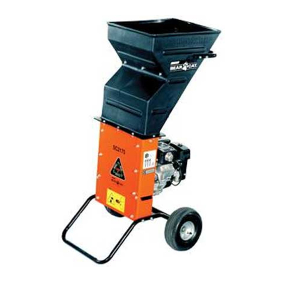
- Page 1 Wood Chipper 4.5” Mini Skid Steer Loaders Operator’s Manual Set-Up Assembly and Parts Information manual has been read and understood.
- Page 2 Read the Operation & Maintenance Manual entirely. When you see this symbol, the subsequent instructions and warnings are serious – follow without exception. Your life and the lives of others depend on it!
- Page 3 Good safety practices not only protect you, but also the people around you. NOTE: Spartan Equipment reserves the right to make improvements in design or changes in specifications at any time without notice and without incurring any obligations to install them on units previously sold.
- Page 4 Equipment Dealer. This document is based on information available at the time of its publication. Spartan Equipment is continually making improvements and developing new equipment. In doing so, we reserve the right to make changes or add improvements to our product without obligation for equipment previously sold.
- Page 5 HOW TO CONTACT SPARTAN EQUIPMENT ADDRESS PHONE E-MAIL HOURS 503 Pulaski Hwy 888.888.1085 Monday - Friday, orders@spartanequipment.com Joppa, MD 21085 8 a.m. to 5 p.m. Eastern Time © 2013, SPARTAN EQUIPMENT, ALL RIGHTS RESERVED. PRODUCED AND PRINTED IN THE U.S.A.
- Page 6 Spartan Equipment dealer as well as subsequent failure or damage that may occur as a result of that work will not be paid under this warranty. Spartan Equipment, Inc. does not warrant replacement components not manufactured or sold by Spartan Equipment, Inc.
-
Page 7: Table Of Contents
TABLE OF CONTENTS SAFETY................. 1 SPECIFICATIONS ............14 1.1 SAFETY ALERT SYMBOL ........1 BOLT TORQUE.............. 15 1.2 BEFORE OPERATING..........1 PARTS ................. 17 1.3 OPERATION SAFETY..........2 8.1 PARTS ORDERING INFORMATION ..... 17 1.4 MAINTENANCE & STORAGE SAFETY ....2 8.2 REPLACEMENTS PARTS ........ -
Page 8: Safety
SAFETY Section Keep safety decals clean and legible. Replace missing 1.1 SAFETY ALERT SYMBOL or illegible safety decals. 4. Obtain and wear safety glasses and use hearing protection at all times when operating this machine. 5. Avoid wearing loose fitted clothing. Never operate this machine while wearing clothing with drawstrings that could wrap around or get caught in the machine. -
Page 9: Operation Safety
SAFETY 1.3 OPERATION SAFETY 1.4 MAINTENANCE & STORAGE SAFETY Always stand clear of discharge area when operating 1. Before inspecting, servicing, storing, or changing this machine. Keep face and body away from feed an accessory, shut off the machine and make sure and discharge openings. -
Page 10: Safety Decals
SAFETY 1.6 SAFETY DECALS See Section 1.5 for decal locations. Familiarize yourself with all of the safety and operating decals on the machine and the associated hazards. See the engine owner's manual or contact the engine manufacturer for engine safety instructions and decals. -
Page 11: Assembly
ASSEMBLY Section 4.5 INCH HYDRAULIC CHIPPER... -
Page 12: Discharge Assembly
2.2 CHUTE ASSEMBLY WARNING 1. Attach the chipper chute to the chipper using four (4) If any bolts or nuts are dropped in the machine, be sure 3/8 x 1" carriage bolts, 3/8" washers and 3/8" nuts. to remove them before starting the machine. Use two bolts on each side. -
Page 13: Features & Controls
ASSEMBLY Section FEATURES & CONTROLS Section Understanding how your machine works will help you achieve the best results when using your machine. The following descriptions define the features and controls of your machine. CHIPPER CHUTE Feed branches no larger than 4.5 inches in diameter into the chipper chute. CHIPPER DEFLECTOR Chipped material exits out the chipper deflector and onto the ground. - Page 14 LOADER MOUNT 4.5 INCH HYDRAULIC CHIPPER...
-
Page 15: Operation
OPERATION Section As with any other piece of outdoor equipment, getting the 4.2 MOUNTING THE CHIPPER TO A feel for how your machine operates and getting to know UTILITY LOADER the best techniques for particular jobs are important to overall good performance. Consult the owner's manual for your utility loader CHIPPING OPERATION before mounting the chipper! -
Page 16: Connecting Couplers
OPERATION 4.4 CONNECTING COUPLERS WARNING Handle pressurized hydraulic fluid carefully. Escaping WARNING pressurized hydraulic fluid may penetrate your skin couplers disconnect. Hydraulic lines may be under pressure due to testing done at the factory. 6. Repeat for the male hose. Consult the owner's manual for your utility loader before mounting the chipper! The chipper is equipped to attach to flush face couplers. -
Page 17: Starting The Chipper
OPERATION Section causing serious injury. This fluid may also be hot enough to burn. Serious infection or reactions can develop if immediate proper medical treatment is not administered. 4.5 STARTING THE CHIPPER Running the utility loader chipper is a one- or two-person operation. -
Page 18: Operating The Chipper
OPERATION The machine chips a variety of materials into a more 4.7 OPERATING THE CHIPPER readily decomposed or handled condition. The following guidelines will help you get started. Run unit at full operating speed before starting to CAUTION chip material. ●... -
Page 19: Service & Maintenance
SERVICE & MAINTENANCE Section 5.1 MAINTENANCE SCHEDULE WARNING The items listed in this service and maintenance schedule To prevent personal injury or property damage: shut are to be checked, and if necessary, corrective action off engine and make sure that all moving parts have taken. -
Page 20: Chipper Blade Maintenance
WARNING BEFORE INSPECTING OR SERVICING ANY PART OF THIS MACHINE, SHUT OFF POWER SOURCE, AND MAKE SURE ALL MOVING PARTS HAVE COME TO A COMPLETE STOP. 5.3 CHIPPER BLADE MAINTENANCE 5.4 REMOVING THE BLADES The chipper blades will eventually become dull, making 1. -
Page 21: Installing The Blades
SERVICE & MAINTENANCE SERVICE & MAINTENANCE WARNING BEFORE INSPECTING OR SERVICING ANY PART OF THIS MACHINE, SHUT OFF POWER SOURCE, AND MAKE SURE ALL MOVING PARTS HAVE COME TO A COMPLETE STOP. 5.6 INSTALLING THE BLADES 1. Lock rotor assembly (Section 5.2). 2. -
Page 22: Replacing Rotor Bearings
WARNING BEFORE INSPECTING OR SERVICING ANY PART OF THIS MACHINE, SHUT OFF POWER SOURCE, AND MAKE SURE ALL MOVING PARTS HAVE COME TO A COMPLETE STOP. 5.9 REPLACING ROTOR BEARINGS REMOVING THE OLD ROTOR BEARING INSTALLING THE NEW ROTOR BEARING 1. -
Page 23: Troubleshooting
SERVICE & MAINTENANCE TROUBLESHOOTING Section Before performing any of the corrections in this troubleshooting chart, refer to the appropriate information contained in this manual for the correct safety precautions and operating or maintenance procedures. Contact your dealer or the factory for service problems with the machine PROBLEM POSSIBLE CAUSES REMEDY... -
Page 24: Specifications
SPECIFICATIONS Section DESCRIPTION ENGLISH METRIC Overall size 39.8 x 36.6 x 42.9" 101 x 93 x 10 cm Overall weight 359 lbs. 163 kg Max chipper capacity 4.5" 11.4 cm Chipper blades 2 reversible (5 x 4 x 3/8") 2 reversible (12.7 x 10.2 x .95 cm) Chipping anvil 4.94 x 1.75 x .375"... -
Page 25: Bolt Torque
SPECIFICATIONS BOLT TORQUE The tables below are for reference purposes only and their use by anyone is entirely voluntary, unless otherwise noted. Reliance on their content for any purpose is at the sole risk of that person and any loss or damage resulting from the use of this information is the responsibility of that person. - Page 26 THIS PAGE LEFT INTENTIONALLY BLANK 4.5 INCH HYDRAULIC CHIPPER...
-
Page 27: Parts
8.2 REPLACEMENTS PARTS IF YOU NEED SERVICE OR PARTS FOR Only genuine Spartan Equipment replacement parts should be used to repair the machine. Spartan Equipment YOUR MACHINE replacement parts are available from your Spartan For service assistance, contact your nearest authorized Equipment Dealer. -
Page 28: Base & Housing (Sn: E02736 And Below)
PARTS 8.3 BASE & HOUSING (SN: E02736 AND BELOW) 4.5 INCH HYDRAULIC CHIPPER... - Page 29 PARTS 8.3 BASE & HOUSING (SN: E02736 AND BELOW) ITEM PART NUMBER DESCRIPTION 12172 DECAL, OPERATING INSTRUCTIONS ISO 12250 DECAL, MAINTENANCE ISO 13890-00 DECAL, DANGER 14942-00 DECAL, MUTILINGUAL MANUAL 15031 WASHER, 3/8 FLAT ZP 15057 BOLT, 3/8 X 1 CRG GR5 NC ZP 15205 BOLT, 3/8 X 5 HEX HD GR5 ZP 15250...
-
Page 30: Base & Housing (Sn: E04641 - Current)
PARTS 8.3 BASE & HOUSING (SN: E04641 - CURRENT) 4.5 INCH HYDRAULIC CHIPPER... - Page 31 PARTS 8.3 BASE & HOUSING (SN: E04641 - CURRENT) ITEM PART NUMBER DESCRIPTION 15057 BOLT, 3/8 X 1" CRG GR5 NC ZP 15205 BOLT, 3/8 X 5" GR5 HEX CPS ZP 15250 WASHER, 5/16" FLAT ZP 15300 BOLT, 5/16 X 5/8 GR5 HEX CPS ZP 15367 BOLT, 5/16 X 3/4 GR5 NC ZP CRG 15904-00...
-
Page 32: Rotor & Hydraulics
PARTS 8.4 ROTOR & HYDRAULICS 4.5 INCH HYDRAULIC CHIPPER... - Page 33 PARTS 8.4 ROTOR & HYDRAULICS ITEM PART NUMBER DESCRIPTION 0103-0112-00 BOLT, 1/2 X 1 CRG GR5 ZP 14768-00 SNAP RING, 1-1/4 EXT. HEAVY DUTY 15011 NUT, 1/2" SERRATED FLANGE 15180 SET SCREW, 1/4 X 5/8 SQ HD 15220-00 BOLT, 1/2 X 1-1/2 CRG SN GR5 ZP 15282 BOLT, 5/16 X 1-1/2 GR5 HEX CPS ZP 15365...
-
Page 34: Attachments
PARTS 8.5 ATTACHMENTS 4.5 INCH HYDRAULIC CHIPPER... - Page 35 PARTS 8.5 ATTACHMENTS ITEM PART NUMBER DESCRIPTION 0103-0848-00 BOLT, 3/8 X 5-1/2 HEX GR5 ZP 12175 DECAL, BLADE DANGER ISO 14771-00 FLAP, CHIPPER CHUTE 14971-00 LATCH, RH HINGE 15031 WASHER, 3/8" FLAT ZP 15057 BOLT, 3/8 X 1" CRG GR5 NC ZP 15301 BOLT, 5/16 X 1"...
-
Page 36: Service Parts & Options
PARTS 8.6 SERVICE PARTS & OPTIONS PART NUMBER DESCRIPTION 74634-00 OPTIONAL 4.5" SQUARE DISCHARGE CHUTE 76295-00 CHIPPER BLADE KIT CHIPPER BLADE KIT, 76295-00 4.5 INCH HYDRAULIC CHIPPER... - Page 37 PARTS LIMITED WARRANTY Spartan Equipment warrants each new machine manufactured by us to be free from defects in material and workmanship for a period of twelve (12) months from date of delivery to the original purchaser. Our obligation under this warranty is to replace free of charge, at our factory or authorized dealership, any part proven defective within the stated warranty time limit.
- Page 38 P/N 300857 Date Printed: 8/2/2017 Printed in U.S.A.
Need help?
Do you have a question about the SC2170 and is the answer not in the manual?
Questions and answers