Table of Contents
Advertisement
Quick Links
SAFETY NOTES
Please read this manual carefully before attempting to install or operate the Access Control
equipment.
This equipment must be installed in line with all relevant regulations and standards.
Make sure that wiring is rated according to fuses and current limits of relevant power supplies.
All connections to this unit must be SELV level. (Safety Extra Low Voltage, BS EN 60950 1992)
Every effort is made to ensure that this manual is complete and free from errors. However we
reserve the right to make changes to these products and this manual without notice.
No liability is accepted for loss damage or injury as a consequence of using these products or
instructions.
These products are not designed for use in life support or safety critical appliances or systems
where malfunction of these products can reasonably be expected to result in personal injury.
Customers using or selling these products for use in such applications do so at their own risk
EMC, LV and
RTTE
Copyright BSB Electronics Ltd 2007,2008, all rights reserved.
HARDWARE MANUAL
Certificate Number 17851
Document Number: 3802-I01 Issue 05
Advertisement
Table of Contents

Summary of Contents for fortessa 3800-F
- Page 1 HARDWARE MANUAL SAFETY NOTES Please read this manual carefully before attempting to install or operate the Access Control equipment. This equipment must be installed in line with all relevant regulations and standards. Make sure that wiring is rated according to fuses and current limits of relevant power supplies. ...
-
Page 2: Table Of Contents
Network LEDS ________________________________________________________ 4 Relay ________________________________________________________________ 4 Fire__________________________________________________________________ 4 Intruder ______________________________________________________________ 4 Notes on the Fire and Intruder Short Circuit Detector LEDs ________________________ 4 FORTESSA Reader (Switch Plate Style) _____________________________ 5 Box Contents ____________________________________________________________ 5 Description _____________________________________________________________ 5 Power __________________________________________________________________ 5... - Page 3 Cables ________________________________________________________________ 14 Desktop Reader _________________________________________________________ 14 LED Indicators _________________________________________________________ 14 The Reader LEDs _____________________________________________________ 14 The USB LEDs _______________________________________________________ 14 The FORTESSA Network LEDs __________________________________________ 14 FORTESSA Credentials __________________________________________ 16 Proximity Card _________________________________________________________ 16 Proximity Key Fob ______________________________________________________ 16...
- Page 4 FORTESSA.net __________________________________________________ 17 Programming ___________________________________________________________ 17 Keyboard ____________________________________________________________ 17 Functions ____________________________________________________________ 18 Set FORTESSA.net IP Address ___________________________________________ 18 Set Server IP Address Filter (Optional) _____________________________________ 18 Controller / Door Name Table _____________________________________ 18...
-
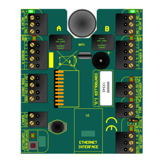
Page 5: System Overview
System Overview Figure 1... -
Page 6: Contents
1 x Hardware Manual Mounting The FORTESSA Controller and its power supply should be mounted in a secure location or on the secure side of the door. This should ideally be as close to the door as possible (Max 100m cable run) to avoid volt drops. -
Page 7: Lock Drive
Cable Network Two core twisted pair cable is to be used to wire the FORTESSA Network (a screened cable can be used to offer better protection). If the optional screened cable is used then the incoming and outgoing screen can be fitted to SCR on the Network terminal block. -
Page 8: Reader
Reader The FORTESSA Readers are connected to the FORTESSA Controller using a standard 4 core cable (alarm cable is suitable). LEDs Status The status LED next to the reset button indicates whether the board has power or not. Reader (A & B) The readers LEDs indicate whether the reader circuit is in overload (red) or if there is activity from the reader itself (green). -
Page 9: Fortessa Reader (Switch Plate Style)
FORTESSA system. The FORTESSA Reader is weather protected to IP66 and suitable for both indoor and outdoor use. Power The FORTESSA Reader uses 12V DC and power is taken from the positive and negative connections of the Reader terminal block on the FORTESSA Controller board. -
Page 10: Mounting
A normally open connection, or “push to make” connection, Request to Exit button may also be fitted to the FORTESSA Reader. The positive of the RQE should be wired in to RQE on the Door terminal block and the negative should be wired in to the negative of the Reader terminal block. -
Page 11: Leds
LEDs There are two bi-colour LEDs on the reader. The lower LED flashes red until a credential is present when it will stay red and hold until the proximity credential is removed. The upper LED will turn green when a valid card is presented to the reader and red when the card is invalid. -
Page 12: Fortessa Reader (Mullion Style)
1 x driver bit for security screws Description The FORTESSA Reader is a passive RFID (Radio Frequency Identification) proximity reader for use with the FORTESSA system. The FORTESSA Reader is weather protected to IP66 and suitable for both indoor and outdoor use. Mounting Drill a 6mm hole at the centre point of the mounting position for the cable. -
Page 13: Fortessa Touch Switch
FORTESSA Touch Switch Description The FORTESSA Touch Switch is capable of detecting near-proximity or touch. It projects a touch proximity field through the dielectric of the enclosure. The patented spread-spectrum charge-transfer technology, coupled with its ability to self-calibrate, makes this an entirely new concept. -
Page 14: Power
Power The FORTESSA Touch Switch uses 12V DC and power is taken from the positive and negative connections of the Reader terminal block on the FORTESSA Controller board. The supply may also be tapped from a nearby FORTESSA reader. Mounting The touch switch may be mounted using the surface box provided or for better aesthetic appearance use a flush back box. -
Page 15: Contact
CONTACT The relay contact of the switch provides C, NC and NO connections. The relay contacts changeover when the surface of the switch is touched. This change over is timed so that it will not hold even if the triggering object is not removed from the surface. - Page 16 Figure 9...
-
Page 17: Fortessa Usb Interface
FORTESSA USB Interface Description The FORTESSA USB Interface allows data to be transferred from a host PC to the FORTESSA controllers. Figure 10 Box Contents 1 x FORTESSA USB Interface 1 x UK standard surface mount single back box ... -
Page 18: Cables
The End of Line resistor should be set to Y on the jumper setting (see figure 11). Cables Two core twisted pair cable is to be used to wire the FORTESSA Network (a screened cable can be used to offer better protection). FORTESSA Controllers can be further linked together in a “daisy chain”, to a maximum of 16 on the whole network, by wiring... - Page 19 Figure 11...
-
Page 20: Fortessa Credentials
The FORTESSA Proximity Key fob is a passive RFID proximity credential which conveniently fits on a key ring which is ideal for people who forget their cards, wallets or purses but remember their car and house keys! The FORTESSA Key Fob is for use with FORTESSA systems only. - Page 21 FORTESSA.net FORTESSA.net provides a 10 / 100 Base T Ethernet connection via an RJ45 socket. This makes the FORTESSA system or parts of it “IP Addressable”. The FORTESSA.net can be used by itself or in conjunction with the FORTESSA USB interface and or additional FORTESSA.net controllers.
- Page 22 Set Server IP Address Filter (Optional) The only required setting is the IP address. Note that if the FORTESSA.net is connected to the same subnet as the Server PC; then the FORTESSA.net IP address can be set from the software. The keyboard is primarily used to set the address when the FORTESSA.net is on the other side of a router on a different subnet.
- Page 23 Controller ID Label Door Name Notes...
Need help?
Do you have a question about the 3800-F and is the answer not in the manual?
Questions and answers