
Related Manuals for Seg CA01H

Summary of Contents for Seg CA01H
- Page 1 CA01H~CA120H CONTROL ACTUATOR CONTROL ACTUATOR INTRUCTION MANUAL CA-01H ~ CA120H Shin Hwa Eng Co., Ltd Ver. 1.0 SHIN HWA Eng.Co.,Ltd.
-
Page 2: Table Of Contents
Caution for Installation of Control Actuator ..............6 How to install control actuator ..................6 Matters to check before operation ................6 2-3 Limit switch adjustment (CA01H~CA10H FB, AB option type) ........6 Position limit switch adjustment method ..............6 Torque limit switch ...................... 7 2-4 Limit switch adjustment (In RB, SB option) .............. -
Page 3: Product Description
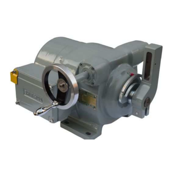
CONTROL ACTUATOR CA01H~CA120H 1 Product description 1-1 Overview The Control Actuator is made by combining all components such as a decelerator, motor, limit switch, overload torque switch, current transmitter, manual handle instrument, and remote control box. It is standardized for precise operation. -
Page 4: Standard Specification
CONTROL ACTUATOR CA01H~CA120H 1-4 Standard specification : Full-shut, outdoor Structure Humidity : 85% or lower type Standard Operating angle : 90˚ : Munsell 7.5BG 6/1.5 painting color : Contact point signal Ambient temperature : -20˚C~60˚C Input signal : Current signal (4~20mA Operating speed : 60sec/90˚... -
Page 5: Installation
CONTROL ACTUATOR CA01H~CA120H 2 Installation 2-1 Structure When you maintain and check the Control Actuator, please refer to the below diagram. Fig.-1. Control Actuator structure 2-2 Transport and Installation Transport When you transport this product, please avoid an accident such as fall and impact. -
Page 6: Caution For Installation Of Control Actuator
② Check if the damper or the valve smoothly operates. In addition, check if the subject to control is completely opened or closed and if it receives an excessive pressure. 2-3 Limit switch adjustment (CA01H~CA10H FB, AB option type) Position limit switch adjustment method (based on clock direction in view of output shaft) ①... -
Page 7: Torque Limit Switch
CONTROL ACTUATOR CA01H~CA120H ⑤ Adjustment of limit switch (LS1) for clock direction position control. When dial gauge is positioned in 0%, please note <Inside indicator for HAB Type> “Fig-5 Limit cam adjustment (Close)” use flat screw driver, LS2P CAM should be rotated slightly into arrow direction and matched until LS2 lamp is on. -
Page 8: Limit Switch Adjustment (In Rb, Sb Option)
CONTROL ACTUATOR CA01H~CA120H 2-4 Limit switch adjustment (In RB, SB option) Position limit switch adjustment method (In viewing of output shaft, it is based on clock direction-Open) ① In Fig-8, upon 2ea of limit switch LS2, LS4 are close direction (clock), below 2ea limit... -
Page 9: Torque Limit Switch
CONTROL ACTUATOR CA01H~CA120H ⑨ Adjustment for open (CCW) direction limit switch Clockwise (LS4) must move before control limit switch (LS2) as the Fig-12, with equal LS2CAM operation method to LS4 CAM. (LS4CAM should be operated a little (around 3˚~5˚) in advance before LS2CAM) Fig-12. -
Page 10: Adjustment Of Resistance (Potentiometer:jp-30)
CONTROL ACTUATOR CA01H~CA120H 2-5 Adjustment of Resistance (Potentiometer:Jp-30) Let the position check needle indicate 50% on the scale plate manually or electrically. Hold the potentiometer with your hand and lift up. And hold the “Adjustment plate” and rotate it so that the point is positioned as shown below (Fig-17.) - Page 11 CONTROL ACTUATOR CA01H~CA120H If DC 20mA is not made, push the SPAN control switch on the R/I Converter for three to four seconds to set to DC20mA. After actuator return to complete close position, measure current of P1 and N1, If DC4mA is not measured, repeat above process and if there is near to DC4mA, the adjustment is completed.
-
Page 12: Adjustment Of Balancing Relay (Sbr-10)
CONTROL ACTUATOR CA01H~CA120H 2-7 Adjustment of balancing relay (SBR-10) After setting dial gauge, limit switch, resistance, and then adjust SBR-10. Put selector switch of local box into remote position. push SW3 (Auto Scan) button switch for 3-4 seconds. In this time, the auto lamp flickers and operates to set the output value (4-20mA DC ). - Page 13 CONTROL ACTUATOR CA01H~CA120H Fig.-20. Fine-adjustment of balancing relay If you want to convert the action direction of actuator, you can adjust it as shown below ① To change open and close, No.2 and No.3 switch must be change from its current position...
-
Page 14: How To Adjust Stp-07 (Indicator)
CONTROL ACTUATOR CA01H~CA120H 2-8 How To adjust STP-07 (Indicator) When input signal is 4mA, in order to show output signal correctly, setting of indicator must be as followings. - Input signal should be adjusted into 4mA and push following picture’s Switch-1 for 2~3 second. -
Page 15: Maintenance
CONTROL ACTUATOR CA01H~CA120H 3 Maintenance 3-1 Troubleshooting Symptom Expected Cause How To Repair Note In case of three phase, Power is not supplied. Supply power. check R, S, and T. The position control Reset to fit the scale switch operates. -
Page 16: Basic Circuit Diagram (Standard)
CONTROL ACTUATOR CA01H~CA120H 4 Basic Circuit Diagram (Standard) 4-1 For Proportional Control (Using Balancing Relay & Potentiometer) Single phase (Up to CA10H) Three phase (Up to CA10H) Three phase (More than CA20H) Ver. 1.0 SHIN HWA Eng.Co.,Ltd. - Page 17 CONTROL ACTUATOR CA01H~CA120H 4-2 For Opening Control (Using Current Transmitter & Potentiometer) Single phase (Up to CA10H) Three phase (Up to CA10H) Three phase (More than CA20H) Ver. 1.0 SHIN HWA Eng.Co.,Ltd.
- Page 18 CONTROL ACTUATOR CA01H~CA120H 4-3 For Opening Control (Using Potentiometer) Single phase (Up to CA10H) Three phase (Up to CA10H) Three phase (More than CA20H) Ver. 1.0 SHIN HWA Eng.Co.,Ltd.
- Page 19 CONTROL ACTUATOR CA01H~CA120H 4-4 For Opening Control (Using Potentiometer) Three phase (Up to CA10H) Single phase (Up to CA10H) Three phase (More than CA20H) Ver. 1.0 SHIN HWA Eng.Co.,Ltd.
- Page 20 CONTROL ACTUATOR CA01H~CA120H SHINHWA ENG. Co., Ltd. Manufacturer information Company Name : SHIN HWA ENG Co., Ltd Address : 242 Cheongneungdae-ro ( 80B -2L ), Namdong gu, Incheon Korea ZIP CODE : 21695 Tel : 82-32-817-8030 Fax : 82-32-815-8036 E mail : 8030@seg.co.kr...
Need help?
Do you have a question about the CA01H and is the answer not in the manual?
Questions and answers