
Summary of Contents for BERGER WDP3-01X
- Page 1 Positioning and Sequence Control Unit for 3-phase Stepping Motors WDP3-01X with OED3 Doc. no. 214.157/DGB Ident. no.: 00441110002 Edition: e220 09.2003 Software version: 03.1XX...
- Page 2 Safety instructions Please read the following safety instructions prior to installation, operation, maintenance and repair of the device. • The intended use of the device under is described “Purpose” and must be observed. • Installation, maintenance and repair of the device shall be performed by a qualified electrician. National regulations concerning –...
- Page 3 Proposals Improvements Berger Lahr GmbH & Co. KG WDP3-01X with OED3 Breslauer Str. 7 Postfach 1180 Edition: d156 08.03 D-77901 Lahr Doc. no. 214.157/DGB Sender: Please inform us, using this form, if you have discovered any errors Name: when reading this document.
-
Page 5: Table Of Contents
2.4.3.1 Signal connection pin assignment 2-10 2.4.4 RS 232 serial interface (OPT.1) 2-12 2.4.5 RS 485 serial interface (OPT.1) 2-14 2.4.6 Encoder interface (OPT.2) 2-16 Setup 2-19 2.5.1 Defaults 2-19 2.5.2 Motor test 2-21 WDP3-01X with OED3 Doc. no. 214.157/DGB... - Page 6 Controller operating modes Switching ON Controller STOP Editing mode Setting the motor phase current Manual mode via front panel Automatic mode Programming Switching OFF Malfunctions Status indicators Troubleshooting tables Repair work Storage, shipment Customer service WDP3-01X with OED3 Doc. no. 214.157/DGB...
- Page 7 Description of accessories 6.2.1 6.2.2 Mains filter 6.2.3 MP 923 interface converter 6.2.3.1 General description 6.2.3.2 Technical data 6.2.3.3 Setup 6.2.3.4 Status indicators 6.2.4 Additional bleed resistor Glossary 6-10 Abbreviations 6-13 Index Corrections and additions WDP3-01X with OED3 Doc. no. 214.157/DGB...
- Page 8 Table of contents WDP3-01X with OED3 Doc. no. 214.157/DGB...
- Page 9 General description General description Structure and characteristics Purpose The WDP3-01X positioning and sequence control unit, which comprises the OED3 operating system, can be used for controlling the following BERGER LAHR 3-phase stepping motors: – with WDP3-014, motors of type size 90, (VRDM 39xx/50 LW.) –...
-
Page 10: General Description
RS 232 Serial interface RS 232 RS 485 LS Serial interface RS 485 LRS 422 IN Encoder interface RS 422 WDP3-01X with OED3 115 VAC/230 VAC Bleed resistor Power supply 325 VDC Processor unit ( P control) µ... - Page 11 The power controller converts the pulse sequence received from the indexer into a current pattern for controlling the 3-phase stepping motor. The motor phase current can be set on the front panel; see chapter 3.5. WDP3-01X with OED3 Doc. no. 214.157/DGB...
-
Page 12: Operating Modes
Setting the operating modes and the motor phase current OPT.1 Encoder OPT.2 PC with ProOED3 programming software Signal Signal/ 24 V DC inputs/outputs 3-phase stepping motor Fig. 1-3 System environment WDP3-01X with OED3 Doc. no. 214.157/DGB... - Page 13 The rotation monitoring feature compares the set and actual positions of the motor and reports a rotation monitoring error if the difference between set and actual position exceeds a certain limit value (19 steps). WDP3-01X with OED3 Doc. no. 214.157/DGB...
-
Page 14: Technical Data
20 VDC to 30 VDC via signal interface Power consumption 1 A max. Ripple voltage < 2 V NOTE The 24 V voltage supply must meet the specifications of the DIN standard VDE 0160 on safety extra-low voltage. WDP3-01X with OED3 Doc. no. 214.157/DGB... - Page 15 1 Mohm RS 485 four-wire interface (option) Short-circuit protected 150 mA max. at short-circuit Internal leakage resistance towards ground 1 Mohm Supply voltage output 12 VDC for MP 923 (10 VDC min., 18 VDC max.) WDP3-01X with OED3 Doc. no. 214.157/DGB...
-
Page 16: Mechanical Data
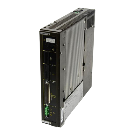
Dimensions (fig. 1-4) 249 x 240 x 52 mm Weight approx. 3200 g 1.3.4 Ambient conditions Ambient temperature 0°C to +50°C Storage temperature -25°C to +70°C Relative humidity 15% to 85% (non-condensing) Fig. 1-4 Dimensions WDP3-01X with OED3 Doc. no. 214.157/DGB... -
Page 17: Regulations
Use motor leads supplied by BERGER LAHR. EMC testing requirements Motor lead length is 10 m. – Insert a mains filter supplied by BERGER LAHR into the mains power supply line. – Install the unit in a switch cabinet. –... - Page 18 General description 1-10 WDP3-01X with OED3 Doc. no. 214.157/DGB...
-
Page 19: Installation
The scope of supply (fig. 2-1) comprises: Qty. Designation Positioning and sequence control unit WDP3-014 with OED3 or WDP3-018 with OED3 Product insert Ground strap Mounting bracket Fan for WDP3-018 with OED3 Fig. 2-1 Scope of supply WDP3-01X with OED3 Doc. no. 214.157/DGB... -
Page 20: Accessories
Signal cable (pulse, direction) for adapter slot option 2 – Set of connectors (all sub-D connectors) – Electronic gear cable NOTE Refer to the sales documentation for the positioning and sequence control unit WDP3-01X with OED3 for the accessory order numbers. WDP3-01X with OED3 Doc. no. 214.157/DGB... -
Page 21: Assembly
Fasten the ground strap supplied at the bottom front of the unit with screws and connect it to a grounded part of the switch cabinet. ATTENTION Clean air supply must be ensured in the switch cabinet. 26 26 Airstream Fig. 2-2 Installation WDP3-01X with OED3 Doc. no. 214.157/DGB... - Page 22 0.5 m/s with fan for WDP3-018 without fan Current Fig. 2-3 Temperature – 0.1 2.0 2.4 2.7 3.1 3.4 3.7 4.1 4.4 4.8 5.1 5.4 5.8 6.1 6.5 6.8 [A] phase current – ventilation WDP3-01X with OED3 Doc. no. 214.157/DGB...
-
Page 23: Wiring
The following cross- sections should be used for bonding lines: 16 mm Cu for bonding lines up to 200 m 25 mm Cu for bonding lines longer than 200 m WDP3-01X with OED3 Doc. no. 214.157/DGB... - Page 24 RS 232 interface, an interface converter (e.g. MP 923, see chapter 6.2.3) must be used. Mains Encoder OPT.2 OPT.1 RS 485/RS 422 Interface converter MP 923 V24/RS 232 Pr oO ED 3 COM 1 COM 2 PC or master Fig. 2-4 Wiring diagram WDP3-01X with OED3 Doc. no. 214.157/DGB...
-
Page 25: Mains Connection
Phase (115 VAC or 230 VAC) Neutral Protective conductor NOTE A mains filter can be inserted in order to shield the unit against inter- ference (see chapter 6.2.2). → → → Fig. 2-5 Mains connection – device end WDP3-01X with OED3 Doc. no. 214.157/DGB... -
Page 26: Motor Connection
The sense of rotation of the motor can be inverted by interchanging two motor leads. In this case, also the limit switch inputs LIMP and LIMN as well as the A and A signals of any rotation monitoring encoder connec- ted must be interchanged. WDP3-01X with OED3 Doc. no.: 214.157/DGB... - Page 27 (connection of second protective conductor) Fig. 2-8 Installing the terminal angle DANGER Electrical device with higher deflection current > 3,5mA. Connection of a second protective conductor absolutely necessary. Please note minimum cross-section according to IEC 60364-5-54. WDP3-01X with OED3 Doc. no.: 214.157/DGB 2-8/1...
- Page 28 Fig. 2-9 Fastening the shield terminal The shield angle is suspended on the bracket from below. The motor cable is not subject to strain and securely grounds shield when installed in this way. Fig. 2-10 Installed motor cable 2-8/2 WDP3-01X with OED3 Doc. no.: 214.157/DGB...
-
Page 29: Signal Interface
All signal connections must be definitely isolated from mains. The voltage towards ground must not exceed 60 VDC or 25 VAC. All signal circuits are internally grounded via a 1 Mohm bleed resistor. Fig. 2-7 Signal connector assembly – device end WDP3-01X with OED3 Doc. no. 214.157/DGB... -
Page 30: Signal Connection Pin Assignment
System and I/O supply voltage ground ← System and I/O supply voltage ground – – Minimum wiring requirement for starting up via front panel (e.g. manual movement mode). Signal = active low I = Input Q = Output 2-10 WDP3-01X with OED3 Doc. no. 214.157/DGB... - Page 31 Installation 24VDC External power supply unit I 13 LIMN I 12 LIMP I 11 I 15 STOP I 10 I 14 REF 24VDC 24VGND IO24VDC Fig. 2-8 Wiring example WDP3-01X with OED3 Doc. no. 214.157/DGB 2-11...
-
Page 32: Rs 232 Serial Interface (Opt.1)
NOTE The attachment screws of the connector shells must have M3 thread on the device end and UNC thread on the PC end. NOTE With an RS 232 interface, networking is not possible. 2-12 WDP3-01X with OED3 Doc. no. 214.157/DGB... - Page 33 Fig. 2-9 Interface connection – device end Controller Controller Shield Shield Female Female Female Cable length Cable length max. 15 m Female max. 15 m Fig. 2-10 Controller/PC wiring Fig. 2-11 Interface connector assembly – device end WDP3-01X with OED3 Doc. no. 214.157/DGB 2-13...
-
Page 34: Rs 485 Serial Interface (Opt.1)
Assemble the two parts of the connector shell with two screws. Fasten the connector to the front panel (item 21) with the bolts. NOTE For a PC with RS 232 interface, the MP 923 interface converter can be used (see chapter 6.2.3). 2-14 WDP3-01X with OED3 Doc. no. 214.157/DGB... - Page 35 Installation 12VDC 12VDC — — SGND Fig. 2-12 Interface connection – device end Fig. 2-13 Interface connector assembly – device end WDP3-01X with OED3 Doc. no. 214.157/DGB 2-15...
-
Page 36: Encoder Interface (Opt.2)
The encoder signal type (pulse/direction or A/B signals) and the internal evaluation (single, double or quadruple) must be selected for an electronic gear (see chapter 6 in the ProOED3 documentation). Fig. 2-14 Encoder connector assembly – device end 2-16 WDP3-01X with OED3 Doc. no. 214.157/DGB... - Page 37 +SENSE to 5VDC on the encoder end of the cable. ATTENTION The TEMP_MOT input is used for detecting a line interruption. For this purpose, TEMP_MOT must be connected to 5VDC on the encoder. WDP3-01X with OED3 Doc. no. 214.157/DGB 2-17...
- Page 38 Direction = 0 CW motor rotation Minimum pulse width 250 ns ⇒ ≥ Direction = 1 CCW motor rotation Minimum pulse break 250 ns Fig. 2-15 Pulse/direction timing Undefined area (pulse) = 2 MHz diagram 2-18 WDP3-01X with OED3 Doc. no. 214.157/DGB...
-
Page 39: Setup
(can be set via front panel) WDP3-018 = 1.0 A as a percentage of front panel setting when stopped when accelerating/decelerating 100% at constant speed Rotation monitoring inactive NOTE For other control parameters, see ProOED3 documentation. WDP3-01X with OED3 Doc. no. 214.157/DGB 2-19... - Page 40 ATTENTION The set phase current must be equal to or less than the nominal phase current specified on the motor type plate (the lower the set phase current, the lower the motor torque). 2-20 WDP3-01X with OED3 Doc. no. 214.157/DGB...
-
Page 41: Motor Test
LIMP and LIMN as well as the signals A and A of any connected encoder for rotation monitoring. NOTE Further tests, e.g. I/O test, are available in the ProOED3 programming software; see ProOED3 documentation. WDP3-01X with OED3 Doc. no. 214.157/DGB 2-21... - Page 42 Installation 2-22 WDP3-01X with OED3 Doc. no. 214.157/DGB...
-
Page 43: Operation
3 s Switch controller off and on again Menue option “Controller/Stop” on PC Editing Automatic mode mode ↵ Enter <X> and < > or select menue option “Controller/Run” on PC Fig. 3-1 Mode transitions WDP3-01X with OED3 Doc. no. 214.157/DGB... -
Page 44: Switching On
Switch on the supply voltage for the processor unit (24 VDC). After power-on, the controller performs a self-test with the hard- ware and software components. Fig. 3-2 shows the power-on sequence of the controller. WDP3-01X with OED3 Doc. no. 214.157/DGB... - Page 45 Switching on Self-test Self test error Error Copy application program from EEPROM and FRAM variable into RAM, if available Minus key STOP pressed ? Start-up routine RUN status Program execution Fig. 3-2 Power-on sequence WDP3-01X with OED3 Doc. no. 214.157/DGB...
-
Page 46: Controller Stop
Press and hold the key and press the key several times until “Ed” is displayed. You can now program the controller with a PC and the ProOED3 software. NOTE For more information, refer to the ProOED3 documentation. WDP3-01X with OED3 Doc. no. 214.157/DGB... -
Page 47: Setting The Motor Phase Current
ATTENTION The set phase current must be equal to or less than the nominal phase current specified on the motor type plate (the lower the set phase current, the lower the motor torque). WDP3-01X with OED3 Doc. no. 214.157/DGB... -
Page 48: Manual Mode Via Front Panel
If you do this, you also have to interchange the limit switch inputs LIMP and LIMN as well as the signals A and A of any connected encoder for rotation monitoring. NOTE In manual mode, all limit switches are monitored. WDP3-01X with OED3 Doc. no. 214.157/DGB... -
Page 49: Automatic Mode
An application program can also be started, stopped or tested (“debugged”) from the programming device (“on-line”). – The program is always executed from program start. → A dot is displayed in the status displays. NOTE For more information, see ProOED3 documentation. WDP3-01X with OED3 Doc. no. 214.157/DGB... -
Page 50: Programming
Before switching off power supply the programme transfer must be completed. Important program data will otherwise be destroyed which can only be restored by the Berger Lahr Service. Documentation note Programming an application program with ProOED3 is described in the ProOED3 documentation. -
Page 51: Malfunctions
3.5 Manual mode Moving the motor manually using the front panel keys during drive setup and testing; see chapter 3.6 Automatic Automatic program execution; mode see chapter 3.7 WDP3-01X with OED3 Doc. no. 214.157/DGB... -
Page 52: Troubleshooting Tables
CW limit switch LIMP actuated Move out of the limit switch range in manual mode; see chapter 3.6. CCW limit switch LIMN actuated Move out of the limit switch range in manual mode; see chapter 3.6. WDP3-01X with OED3 Doc. no. 214.157/DGB... - Page 53 The mains supply voltage must be disconnected for any check on the mains, motor, or bleed resistor wiring. NOTE If error handling is not effected by the application program, errors can be acknowledged via the front panel keys. WDP3-01X with OED3 Doc. no. 214.157/DGB...
- Page 54 Motor and positioning and Use the appropriate motor type; see sequence control unit do not chapter 6.1. match DANGER The mains supply voltage must be disconnected for any check on the mains, motor, or bleed resistor wiring. WDP3-01X with OED3 Doc. no. 214.157/DGB...
-
Page 55: Repair Work
(use original wrapping, if possible). – Units or PC boards marked with the symbol may only be packed in an electrostatically protected environment. WDP3-01X with OED3 Doc. no. 214.157/DGB... - Page 56 Malfunctions WDP3-01X with OED3 Doc. no. 214.157/DGB...
-
Page 57: Customer Service
Phone: +49 (0) 7808 - 943 - 226 Fax: +49 (0) 7808 - 943 - 499 Internet e-mail: hotline@berger-lahr.com Of course, the Technical Services department also offer the following services: – On-site maintenance and – direct communication with your service specialist. WDP3-01X with OED3 Doc. no. 214.157/DGB... - Page 58 Customer service WDP3-01X with OED3 Doc. no. 214.157/DGB...
-
Page 59: Appendix
The interfaces installed in the device are indicated on the type plate. The following abbreviations are used: RS 232 Serial interface RS 232 RS 485 LS Serial interface RS 485 LRS 422 IN Encoder interface RS 422 WDP3-01X with OED3 Doc. no. 214.157/DGB... -
Page 60: Description Of Accessories
Appendix Description of accessories Mains Fig. 6-1 Accessories WDP3-01X with OED3 Doc. no. 214.157/DGB... - Page 61 10 m 15 m 20 m 25 m 30 m 50 m 75 m 100 m 200 m Ready-made cables are available in the following lengths: 1.5 m 2 m NOTE Refer to the sales documentation for the positioning and sequence control unit WDP3-01X with OED3 for the accessory order numbers. WDP3-01X with OED3 Doc. no. 214.157/DGB...
-
Page 62: Fan
Fasten the fan to the bottom of the unit with four screws. Connect the fan to the external 24 VDC voltage supply. NOTE Ensure that the airstream in and around the unit is unobstructed. Fig. 6-2 Fan WDP3-01X with OED3 Doc. no. 214.157/DGB... -
Page 63: Mains Filter
Mains filter A mains filter (fig. 6-3) can be inserted into the mains supply line for radio interference suppression. NOTE When connecting the mains filter, the EMC testing specifications of BERGER LAHR must be observed. → → → L’ N’... -
Page 64: Mp 923 Interface Converter
The interface converter must be powered either via the power supply unit connection (2-pin female diode connector) or via the RS 485 (RS 422) connector with 12 VDC. With BERGER LAHR positioning units (e.g. WDP3), power is supplied via the RS 485 (RS 422) connection. -
Page 65: Setup
Wire the MP 923 interface converter in accordance with fig. 6-5. NOTE The MP 923 is supplied with 12 VDC power via the RS 485 (RS 422) connector of the BERGER LAHR controller. ATTENTION The interface cables must be shielded on both ends via the connec-... - Page 66 15 m max. conn. connector RS 422 RGND Shield RS 485/RS 422 V24/RS 232 Female connector RS 232 Signal ground Female connector Cable length Male 15 m max. conn. Fig. 6-5 MP 923 interface converter setup WDP3-01X with OED3 Doc. no. 214.157/DGB...
-
Page 67: Additional Bleed Resistor
Provide the two bleed resistor leads with wire end ferrules on the device end. Connect the two litz wires to the terminals at the bottom of the unit. WDP3-01X Fig. 6-6 Additional bleed resistor WDP3-01X with OED3 Doc. no. 214.157/DGB... -
Page 68: Glossary
Pulse signals of an encoder. For one motor revolution, a defined number of pulse signals (e.g. 1000) is generated by the encoder. The encoder signals are subjected to single, double or quadruple evaluation. 6-10 WDP3-01X with OED3 Doc. no. 214.157/DGB... - Page 69 A motor is controlled by a power controller. The power controller converts positioning signals from the processor control into signals for motor control. Pulse/direction signals Signals for reference variable input for an electronic gear. WDP3-01X with OED3 Doc. no. 214.157/DGB 6-11...
- Page 70 Serial interface for a network configuration. Teach-in The teach-in function is used for storing positions which have been approached by manual control. Upload The upload function is used for reading data from the controller. 6-12 WDP3-01X with OED3 Doc. no. 214.157/DGB...
-
Page 71: Abbreviations
Doc. no. Documentation number Decentralized peripheral equipment Encoder Fault current Height Unit Input Input/Output Interbus-S interface Light Emitting Diode Motor PBDP Profibus-DP interface Personal Computer PELV Protected Extra Low Voltage Programmable Logic Controller Output WDP3-01X with OED3 Doc. no. 214.157/DGB 6-13... - Page 72 Appendix 6-14 WDP3-01X with OED3 Doc. no. 214.157/DGB...
-
Page 73: Index
RS 232 serial interface 1-7, 2-12 RS 485 serial interface 1-7, 2-14 Signal interface 1-7, 2-9 Defaults 2-19 Displays Luminous displays Editing mode Encoder signal type A/B signals 2-17 Pulse/direction 2-18 Error code Front panel WDP3-01X with OED3 Doc. no. 214.157/DGB... - Page 74 Motor current reduction 2-19 Normalizing factors 2-19 Number of steps 2-19 Operating modes Rotation monitoring Set speed 2-19 Start speed 2-19 System speed 2-19 Timing diagram Encoder signals A/B 2-17 Pulse/direction 2-18 Ventilation Wiring layout WDP3-01X with OED3 Doc. no. 214.157/DGB...
-
Page 75: Corrections And Additions
Corrections and additions Corrections and additions At present there are no corrections or additions. WDP3-01X with OED3 Doc. no. 214.157/DGB... - Page 76 Corrections and additions WDP3-01X with OED3 Doc. no. 214.157/DGB...
Need help?
Do you have a question about the WDP3-01X and is the answer not in the manual?
Questions and answers