Elesa UC-RF Operating Instructions Manual
Hide thumbs
Also See for UC-RF:
- Quick user manual (4 pages) ,
- Operating instructions manual (50 pages)

Related Manuals for Elesa UC-RF


Summary of Contents for Elesa UC-RF
- Page 1 OPERATING INSTRUCTIONS DD51-E-RF CONTROL UNIT FOR DD52R-E-RF MPI-R10-RF UC-RF (GN 9150)* *(Product series valid only for Germany)
-
Page 2: Table Of Contents
3. Connections and mounting 3.1. Power supply 3.2. PLC connection 3.3. Antenna 4. System configuration 4.1. IP address 5. UC-RF status leds 6. BUS variants 6.1. ETHERNET/IP (CE.99225) 6.2. PROFINET (CE.99231) 6.3. MODBUS/TCP (CE.99229) APPENDIX A – Status and command word APPENDIX B –... -
Page 3: Safety Instructions
To maintain the product in this state, it is necessary that it is assembled and used properly, in the closest compliance with this instruction manual and with the following specific safety precautions. Before installing and using the UC-RF read carefully this manual. This manual is intended as an indispensable supplement to the existing documentation (catalogues, data sheets and assembly instructions). - Page 4 Do not open or modify the case of the indicator. Tampering with this product may endanger the correctness and accuracy of its operation. In case of malfunction, do not attempt any repair to the units and contact Elesa sales office. NOTE This equipment has been tested and found to comply with the limits for a Class A digital device, pursuant to part 15 of the FCC Rules.
-
Page 5: Description
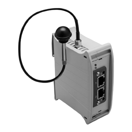
The control unit (UC-RF) is a standard DIN rail module. This unit is provided with a socket for connection to a power source, a standard industrial bus interface connector for the communication with the PLC and an antenna output for the RF communication with the RF electronic position indicator and measuring system (to be ordered separately). -
Page 6: Connections And Mounting
3.2. Connection to the PLC The UC-RF must be connected to the PLC via an Ethernet RJ45 cable by using one of the two ports on the front of it (see drawing below). Both ports are equivalent. In case two PLCs (or PLC+PC) are connected, make sure that conflicts are avoided. -
Page 7: System Configuration
4. System configuration The Elesa wireless network consists in up to 100 sub networks identified by a NetId number from 0 to 99. Each subnet can address up to 36 remote devices, each transmitting on a different channel (Net CH). - Page 8 CH33 to CH36 on remote device NOT usable. f In systems using UC-RF with software release 0F 3E 10 18, avoid channels lower than CH 04. f The UC-RF will not start the network scan until it receives a valid networkID from the PLC after power-on.
-
Page 9: Ip Address
PLC and/or the IP address configuration. If RED LED and GREEN LED stay ON, the UC-RF is waiting for the NEtId to be set. If RED LED stays ON, please, contact Elesa customer service. -
Page 10: Bus Variants
If the link is not reachable, please contact the Elesa customer service. The EDS allows the PLC to recognize the UC-RF on the Ethernet/IP bus. Then it is needed to configure all the I/O instances as described below (refer to Appendix A for status and command word definition). - Page 11 Control unit for DD51-E-RF DD52R-E-RF MPI-R10-RF UC-RF PLC connection, data transmission via radio frequency Status LEDs Network Status LED LED State Description No power or no IP address Green Online, one or more connections established (CIP Class 1 or 3)
-
Page 12: Profinet (Ce.99231)
If the link is not reachable, please contact the Elesa customer service. The GSD file allow the PLC to recognize the UC-RF on the Profinet bus. Then it is needed to configure 56 8bits long slots as follows: - Slot 0 to Slot 27 - output (PLC to UC) - Slot 28 to Slot 55 - input (UC to PLC) Each data block length is 224 bytes. - Page 13 Control unit for DD51-E-RF DD52R-E-RF MPI-R10-RF UC-RF PLC connection, data transmission via radio frequency Status LEDs Network Status LED LED State Description Comments - No power Offline - No connection with IO Controller - Connection with IO Controller established Green...
-
Page 14: Modbus/Tcp (Ce.99229)
PLC connection, data transmission via radio frequency 6.3. MODBUS/TCP (CE.99229) The memory of the UC-RF is organised as follows (refer to Appendix A for command and status word). Each location is 2 Bytes (16bits) long. Use function code 3 (Read/write multiple registers). - Page 15 Control unit for DD51-E-RF DD52R-E-RF MPI-R10-RF UC-RF PLC connection, data transmission via radio frequency Status LEDs Network Status LED LED State Description No power or no IP address Green Module is in Process Active or Idle state Green, flashing Waiting for connection...
-
Page 16: Appendix A - Status And Command Word
- enable channel. Set to enable the corresponding channel. Clear to disable. When disabled, the UC-RF will ignore it. In case a quick connection with a single channel is needed, it is recommended to disable momentarily the other channels - then the UC-RF will communicate only with the channel enabled. bit1-bit14 - reserved bit15 - Set to indicate the target field contains a valid target. -
Page 17: Appendix B - Bus Interface Connector
Control unit for DD51-E-RF DD52R-E-RF MPI-R10-RF UC-RF PLC connection, data transmission via radio frequency Appendix B – Bus interface connector The ethernet interface supports 10/100Mbit, full or half duplex operation. Item Network Status LED Module Status LED Link/Activity LED (port 1) Link/Activity LED (port 2) Pin n. -
Page 18: Appendix C - Technical Data
Control unit for DD51-E-RF DD52R-E-RF MPI-R10-RF UC-RF PLC connection, data transmission via radio frequency Appendix C – Technical data Electrical data Supply voltage 24 VDC ±5 % Power consumption 50 mA Reverse polarity Protected Voltage transitions Protected Frequency range 2.400-2.480GHz... - Page 19 Control unit for DD51-E-RF DD52R-E-RF MPI-R10-RF UC-RF PLC connection, data transmission via radio frequency EU DECLARATION OF CONFORMITY (DOC) COMPANY NAME: Elesa S.p.a. POSTAL ADDRESS: Via Pompei 29 POSTCODE AND CITY: 20900 Monza TELEPHONE NUMBER: +39 039 28111 E-MAIL ADDRESS: info@elesa.com...
- Page 20 The Company Elesa S.p.A. can neither be held legally responsible nor liable for lacking or incorrect information and the ensuing consequences. The Company Elesa S.p.A. reserves the right to alter or improve the electronic position indicators or parts of them and/or the enclosed brochures without prior notice.
Need help?
Do you have a question about the UC-RF and is the answer not in the manual?
Questions and answers