Advertisement
Quick Links
Advertisement

Subscribe to Our Youtube Channel
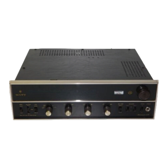
Summary of Contents for Scott 631 Receiver
-
Page 2: Specifications
Scott ... where innovation is a tradition ® SCOTT H. H. Scott, Inc. 111 Powdermill Road, Maynard, Mass., 01754 SERVICE MANUAL SPECIFICATIONS (FM-MPX) TUNER 2-. 0 microvo 1 ts Usable Sensitivity (I H F) Cross Modulation Rejection 80 db Signal to Noise Ratio below 100% modulation 60 0.8%... -
Page 3: Audio Test
AUDIO TEST 0.8% Total Harmonic Distortion ± 18-25,000 1 db Frequency Response Power Bandwidth at Rated Distortion 25-20,000 Hz (IHF Method) Hum and Noise (Phono) 105-120v, 50-60 Hz Range of Line Voltage and Frequency Power Consumption - 117 v at 60 Hz (AC only) 25-95 watts EQUIPMENT NEEDED... - Page 8 AM TEST TUNER-AM SECTION Switch tuner to AM position, output from tape output jack. Connect signal generator at 455 kHz through .05 capacitor to green lead from If board to feedthrough terminal in front end. Clip ground lead to chassis. Remove RF transistor.
-
Page 9: Front End Alignment
FRONT END ALIGNMENT FM FRONT END ALIGNMENT FOR FM SECTION Connect RF generator to the antenna terminals with the following adaptations: 270Jt FROM GEN. .__ .._ _____ ► GND. Set RF generator and FM tuning dial to 92 mHz. Generator output should be about 6 uv. -
Page 10: Front End
FRONT Bt12V AM AGC +12 AM OUT 10.7 MHz AM LOW l0.7 MH2 Z-AMLFM-8 c:� FRONT END 202 H9J..-tl---+--M - E - T E _R __ QZ.03c; DRIVE b Q2.01 GNC. J: t rg�@ @�)( �HlGH ® LOW@FN'I RF FM OSC HIGH Mechanical layout of Front Ends denoting, Osc i I la tor,...

Need help?
Do you have a question about the 631 Receiver and is the answer not in the manual?
Questions and answers